Table of Contents
Advertisement
Quick Links
Dual Swing Gate Opener
User's Manual
Model:
MT9012
TOPENS Website
www.topens.com
Email: support@topens.com
★ Please read and follow all warnings, precautions and instructions before
installation and use.
★ Never connect the solar panel to the control board directly to charge the battery.
★ Periodic checks of the opener are required to ensure safe operation.
★ Save this manual.
C030615
VER 22b
Advertisement
Table of Contents

Related Manuals for Topens MT9012


Summary of Contents for Topens MT9012
- Page 1 Dual Swing Gate Opener User’s Manual Model: MT9012 TOPENS Website www.topens.com Email: support@topens.com ★ Please read and follow all warnings, precautions and instructions before installation and use. ★ Never connect the solar panel to the control board directly to charge the battery.
- Page 2 Visit: www.topens.com Please record the product model, your email address etc. in the spaces provided below. Refer to this list when contacting TOPENS for technical service or assistance with your automatic gate opener. Where did you purchase? (Amazon.com; Amazon.ca: Amazon.co.uk, Amazon.de; Other, Please...
-
Page 3: Table Of Contents
MT9012 Parts List................................3 Extra parts for rounded gate post............................3 Accessories Parts (Included in some models, refers to the actual package).............4 Optional Accessories Parts List (Available at TOPENS Store)..................4 Replacement Parts................................4 Tools Needed:................................... 5 Technical Specifications & Features..........................5 Dual Gate Overview.................................6... -
Page 4: Safety Installation Information
Care shall be exercised to reduce the risk of nuisance Safety Installation Information tripping, such as when a vehicle trips the safety sensor while READ and FOLLOW all instruction. the gate is still moving. The gate opener is intended for use with Class I vehicular One or more non-contact sensors (safety sensors) shall swing gates. - Page 5 NOTE: TOPENS Gate Operator can be used for driveway gates made by steel, wood, vinyl, and shaped as panel, tube, and chain-link. While use on solid surface gates is NOT recommended. Solid surface gates have a high resistance to the wind. If the wind is strong enough, the operator will obstruct and stop.
-
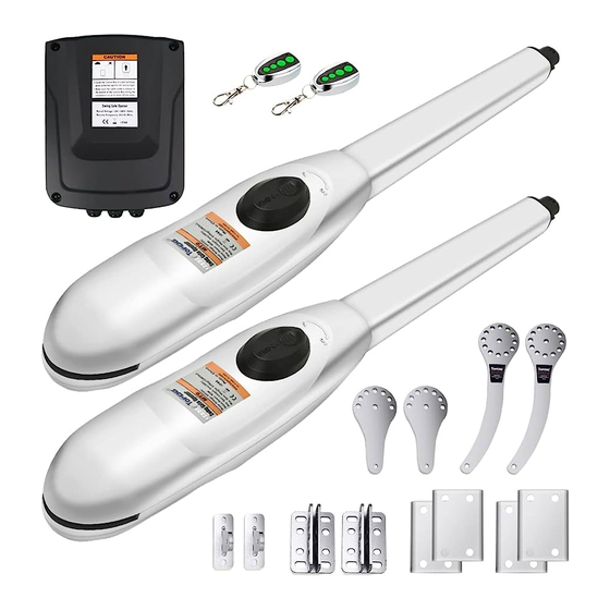
Page 6: Mt9012 Parts List
MT9012 Parts List Extra parts for rounded gate post... -
Page 7: Accessories Parts (Included In Some Models, Refers To The Actual Package)
Accessories Parts (Included in some models, refers to the actual package) JD24VY 24V Warning TC102 Photo Eye 25FT Extension Light Beam Sensor 5 Conductor Cable Optional Accessories Parts List (Available at TOPENS Store) TC186-R WiFi TC186 WiFi ERM12 External M12 Remote Control Smartphone Remote Smartphone Remote... -
Page 8: Tools Needed
WARNING: Changes or modifications not expressly specified by this user manual, TOPENS could void the warranty of this equipment. Tools Needed: ·Power Drill ·Tape Measure ·Open End Wrenches - 14# &17# or Adjustable Wrenches ·Wire Strippers ·C-Clamps - small, medium, and large ·Level... -
Page 9: Dual Gate Overview
Features: ·Built in max. Motor running time (MRT) adjustable ·Soft start and soft stop for multiple safety protection (1-50 seconds) ·Emergency release key in case of power failure ·Digital display indicates the running situation and ·Dual/Single gate running mode setting menu ·... -
Page 10: Preparation For Installation
Preparation for Installation There are two installation types for the gate opener, Pull-to-Open and Push-to-Open. In the Push-to-Open installation, gate opens out from the property. A Push-To-Open Bracket is required to be used for each gate. NOTE: Ensure the gate does not open into public areas. One more person will help when installing. The gate opener can be either installed on square gate post or rounded gate post. - Page 11 1. Insert the M10 x 30 bolts through the center holes of the post bracket and Pull to Open Bracket as shown. Place ¢10 washers , ¢10 lock washers and M10 nuts on the bottom of the bolts and hand tighten. 2.
- Page 12 6. Sign the bolt-hole point on the gate post and gate. Do this by placing a punch or a sign in the middle of each bolt slot on the post bracket assemblies and the gate bracket. It allows slight adjustments to the post bracket.
-
Page 13: Install The Opener On The Gate - For Push To Open
11. Open the release hole plug on the top of the gate opener, insert the release key, and turn the key 90° counterclockwise. This restores normal operation. NOTE: The setting of the PULL/PUSH TO OPEN of the control board should be in accordance with the installation. - Page 14 1. Insert the M10 x 30 bolts through the center holes of the post bracket and Push to Open Bracket as shown. Place ¢10 washers , ¢10 lock washers and M10 nuts on the bottom of the bolts and hand tighten. 2.
- Page 15 6. Sign the bolt-hole point on the gate post and gate. Do this by placing a punch or a sign in the middle of each bolt slot on the post bracket assemblies and the gate bracket. It allows slight adjustments to the post bracket. Then remove the post bracket and gate bracket by taking off the C-clamps.
-
Page 16: Mounting The Control Box
11. Open the release hole plug on the top of the gate opener, insert the release key, and turn the key 90° counterclockwise. This restores normal operation. NOTE: The setting of the PULL/PUSH TO OPEN of the control board should be in accordance with the installation. -
Page 17: Connection Of The Power Supply
and sunlight. CAUTION: Make sure the cable outlet hole in the Control Box is always down during installation so as to drain off the water. Step 3 Insert the cable of the second gate opener and alarm lamp cables into the control box through middle strain relief. -
Page 18: Connecting Of The Control Board
Connecting of the Control Board... - Page 19 Motor connection for PUSH-TO-OPEN The motors’ power wires and limit wires connection by “Push to Open” is different from the connection by “Pull to Open”. So motor 1 and motor 2 wires should be connected to the control box as the instruction on the right. The black wire should be inserted into the Motor+ terminal, the red wire should be inserted into the Motor- terminal, the yellow wire into ULT1 terminal, the blue wire into DLT1...
-
Page 20: How To Program Or Erase The Remote
the button (open-stop-close-stop-open). Exit Wand (optional) Please note that the adapter board of the exit wand should be inserted into the main control board of the gate opener before using. The BLACK and the BLUE wire of the exit wand should be connected into the “LOOP” terminal, no matter the polarity. -
Page 21: How To Use The Remote To Operate Your Gate Opener
2. Use one remote to operate TOPENS swing gate opener & sliding gate opener at the same time All of TOPENS sliding gate opener have midway mode. Button B is designed to realize midway function (refer to more details in our TOPENS sliding gate opener manual). So it is must program button A with sliding gate opener, while you may program either C button or D button with TOPENS swing gate opener. -
Page 22: Setting Of The Control Board
NOTE: Every step for pressing button during program must be finished within 1 second to ensure successful programming. Setting of the Control Board WARNING: Ensure the gate opener is Power Off when you make any adjustment of the gate opener. Keep away from the path of the gate during you set the gate opener system in case of the unexpected gate moving. - Page 23 Press the “FUNC” button to store the data when the master/slave gate is chosen. The Digital Display will indicate “P3”. Now Master/Slave Gate Set is finished. (Factory set is “01”) 4. Set the Open Interval between Master and Slave Gate When the Digital Display indicates “P3”, the gate opener is on the Open Interval between Master/Slave Gate Setting.
- Page 24 Now stall force of gate opener 1 is finished. (Factory set is Level 3) 6-b Adjust Stall Force of Gate Opener 2 When the Digital Display indicates “P6”.you can adjust force of gate opener 2. Please perform the same procedure as gate opener 1 (6-a). Press the “FUNC”...
-
Page 25: Indicate Illustration On The Digital Display When Gate Opener Is Running
You can press the “INC” or “DEC” button to set the period of soft start. There is 1-9 seconds available in setting. Press the “FUNC” button to store the data when the period is set. The Digital Display will indicate “PC”. (Factory set is 3 seconds) 11. -
Page 26: Maintenance
firmly. Limit setting for master gate is finished now. The slave gate is totally the same. 2 For Push-to-Open Installation, adjust the limit switch B to determine the open position: Turn on power to operate the gate opener, then the arm extends to open the gate. If the arm opens over the desired open position, press the remote control to stop the opener. - Page 27 2. Arm is incorrectly installed. Disconnect the motor housing from the arm and check if the arm moves freely. 3. Gate is excessively heavy or hinges are bad. Check the gate is within the ratings for this product. Disconnect the arms and verify that both gates swing easily. Lubricate or replace hinges as necessary. 4.
-
Page 28: Quick-Setting Guide
Quick-Setting Guide... - Page 32 Your comments and suggestions are important to us as they help us provide the best possible service. Should you have any need to contact us, the info below will help you get in touch: TOPENS Website www.topens.com Contact Us: E-mail: support@topens.com Kindly include your Product Model, Purchasing Date &...
Need help?
Do you have a question about the MT9012 and is the answer not in the manual?
Questions and answers