Table of Contents
Advertisement
Quick Links
Dual Swing Gate Opener
User's Manual
Model:
KD902
TOPENS Website
www.topens.com
Email: support@topens.com
★ Please read and follow all warnings, precautions and instructions before
installation and use.
★ Never connect the solar panel to the control board directly to charge the battery.
★ Periodic checks of the opener are required to ensure safe operation.
★ Save this manual.
C030413
VER 21a
Advertisement
Table of Contents

Related Manuals for Topens KD902


Summary of Contents for Topens KD902
- Page 1 Dual Swing Gate Opener User’s Manual Model: KD902 TOPENS Website www.topens.com Email: support@topens.com ★ Please read and follow all warnings, precautions and instructions before installation and use. ★ Never connect the solar panel to the control board directly to charge the battery.
- Page 2 Visit: www.topens.com Please record the product model, your email address etc. in the spaces provided below. Refer to this list when contacting TOPENS for technical service or assistance with your automatic gate opener. Where did you purchase? (Amazon.com; Amazon.ca: Amazon.co.uk, Amazon.de; Other, Please...
-
Page 3: Table Of Contents
Safety Installation Information .......................... 1 KD902 Parts List .............................. 3 Accessories Parts (Included in some models, refers to the actual package) ............3 Optional Accessories Parts List (Available at TOPENS Store) ................4 Replacement Parts ............................4 Tools Needed: ..............................4 Technical Specifications &... -
Page 4: Safety Installation Information
use on any pedestrian gate. Pedestrians must be Safety Installation Information supplied with a separate pedestrian access. 1. READ and FOLLOW all instruction. For an installation utilizing non-contact sensors The gate opener is intended for use with Class I (safety sensors), see product manual on the vehicular swing gates. - Page 5 NOTE: TOPENS Gate Operator can be used for driveway gates made by steel, wood, vinyl, and shaped as panel, tube, and chain-link. While use on solid surface gates is NOT recommended. Solid surface gates have a high...
-
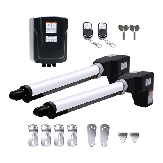
Page 6: Kd902 Parts List
KD902 Parts List Accessories Parts (Included in some models, refers to the actual package) -
Page 7: Optional Accessories Parts List (Available At Topens Store)
PKMJ1A Control Board ALS01 Limit Switch MK01 Hardware Kit WARNING: Changes or modifications not expressly specified by this user manual, TOPENS could void the warranty of this equipment. Tools Needed: ·Power Drill ·Tape Measure ·Open End Wrenches - 14# &17# or Adjustable Wrenches ·Wire Strippers ·C-Clamps - small, medium, and large ·Level... -
Page 8: Technical Specifications & Features
Technical Specifications & Features Specifications Model: KD902 Input: 110V~120V/60Hz or 220~240V/50Hz Motor Voltage: 24VDC Power: 2×80W Current: Actuator Speed: 16mm/s(0.6 in/s) Max. Actuator Travel: 385mm(15.2 in) Ambient Temperature: -20℃~ +50℃ (-4° F to 122° F) Protection Class: IP44 NOTE: ―NR" indicates this size and weight combination is NOT recommended for one arm actuator. -
Page 9: Installation Overview
Installation Overview Pull-to-Open Gates Important: The second gate opener cable should be put into the PVC conduit (not provided) which is buried underground .This protects the cable from lawn mowers and string trimmers. -
Page 10: Preparation For Installation
Preparation for Installation There are two installation types for the gate opener, Pull-to-Open and Push-to-Open. In the Push-to-Open installation, gate opens out from the property. A Push-To-Open Bracket (PSO part) is required to be used for each gate. NOTE: Ensure the gate does not open into public areas. One more person will help when installing. The gate opener is mounted to the gate and to the gate post. - Page 11 1. Insert the bolts through the holes of post bracket and post pivot bracket as shown. Place washers and nuts on the bottom of the bolts and hand tighten. 2. Attach the gate bracket and post bracket assy. to the opener by inserting a clevis pin.
- Page 12 6. Sign the bolt-hole point on the gate post and gate. Do this by placing a punch or a sign in the middle of each bolt slot on the post bracket and the gate bracket. It allows slight adjustments to the post bracket. Then remove the opener and brackets assy.
-
Page 13: Install The Opener On The Gate - For Push To Open
12. Open the release hole plug on the top of the gate opener, insert the release key, and turn the key 90° counterclockwise. This restores normal operation. Install the Opener on the Gate – for Push to Open The position of Post Bracket is very important. The following illustrations and tables are required to determine the proper mounting position for the Post Bracket. - Page 14 1. Insert the bolts through the holes of post bracket and PSO part (push to open bracket) as shown. Place washers and nuts on the bottom of the bolts and hand tighten. 2. Attach the gate bracket and post bracket assy. to the opener by inserting a clevis pin.
- Page 15 6. Sign the bolt-hole point on the gate post and gate. Do this by placing a punch or a sign in the middle of each bolt slot on the post bracket and the gate bracket. It allows slight adjustments to the post bracket. Then remove the opener and brackets assy.
-
Page 16: Mounting The Control Box
12. Open the release hole plug on the top of the gate opener, insert the release key, and turn the key 90° counterclockwise. This restores normal operation. Mounting the Control Box Step 1 To install the control box use the deck screws (not provided). Even though the control box is waterproof designed, for safety reason and a longer service life, it is recommended to install the control box inside a secure surface and at least 100 cm (40 inches) above the ground to... -
Page 17: Connection Of The Power Supply
Step 3 Insert the cable of the second gate opener and alarm lamp cables into the control box through middle strain relief. Then repeat step 2. Step 4 Insert other cables into the control box through rightmost strain relief. Then repeat step 2. NOTE: Only motor cables (1.5m length) are provided. -
Page 18: Connecting Of The Control Board
Connecting of the Control Board... -
Page 19: Motor Connection For Push-To-Open
Motor connection for PUSH-TO-OPEN The motors’ power wires and limit wires connection by ―Push to Open‖ is different from the connection by ―Pull to Open‖. So motor 1 and motor 2 wires should be connected to the control box as the instruction on the right. The black wire should be inserted into the Motor+ terminal, the red wire should be inserted into the Motor- terminal, the yellow wire into ULT1 terminal, the blue wire into DLT1 terminal and the green wire is... -
Page 20: How To Program Or Erase The Remote
Exit Wand (optional) Please note that the adapter board of the exit wand should be inserted into the main control board of the gate opener before using. The BLACK and the BLUE wire of the exit wand should be connected into the “LOOP” terminal, no matter the polarity. -
Page 21: How To Use The Remote To Operate Your Gate Opener
All of TOPENS sliding gate opener have midway mode. Button B is designed to realize midway function (refer to more details in our TOPENS sliding gate opener manual). So it is must program button A with sliding gate opener, while you may program either C button or D button with TOPENS swing gate opener. -
Page 22: Setting Of The Control Board
NOTE: Every step for pressing button during program must be finished within 1 second to ensure successful programming. Setting of the Control Board WARNING: Ensure the gate opener is Power Off when you make any adjustment of the gate opener. Keep away from the path of the gate during you set the gate opener system in case of the unexpected gate moving. - Page 23 Press the “FUNC” button to store the data when the master/slave gate is chosen. The Digital Display will indicate “P3”. Now Master/Slave Gate Set is finished. (Factory set is “01”) 4. Set the Open Interval between Master and Slave Gate When the Digital Display indicates “P3”, the gate opener is on the Open Interval between Master/Slave Gate Setting.
- Page 24 Now stall force of gate opener 1 is finished. (Factory set is Level 3) 6-b Adjust Stall Force of Gate Opener 2 When the Digital Display indicates “P6”.you can adjust force of gate opener 2. Please perform the same procedure as gate opener 1 (6-a). Press the “FUNC”...
-
Page 25: Indicate Illustration On The Digital Display When Gate Opener Is Running
10. Set the Period of Soft Start When the Digital Display indicates “Pb”, the gate opener is ready for setting period of soft start. You can press the “INC” or “DEC” button to set the period of soft start. There is 1-9 seconds available in setting. Press the “FUNC”... -
Page 26: Maintenance
press the remote control to stop the opener. Use a screwdriver to loosen the screw of the limit B, slightly slide the limit switch B inwards. If the arm closes halfway and fails to get to the desired closed position, slightly slide the limit switch B outwards. Please repeat the above steps, until the arm could arrive and automatically stop at the desired close position. - Page 27 ◆Opener powers up but does not run. 1. Check if the arm cable is loosening. Verify that all of the wires of the arm are secure to the terminals of the control board. 2. Arm is incorrectly installed. Disconnect the motor housing from the arm and check if the arm moves freely. 3.
-
Page 28: Quick-Setting Guide
Quick-Setting Guide... - Page 32 Your comments and suggestions are important to us as they help us provide the best possible service. Should you have any need to contact us, the info below will help you get in touch: TOPENS Website www.topens.com Contact Us: E-mail: support@topens.com Kindly include your Product Model, Purchasing Date &...
Need help?
Do you have a question about the KD902 and is the answer not in the manual?
Questions and answers