Keithley DMM6500 Manual
6 1/2-digit multimeter with scanning
Hide thumbs
Also See for DMM6500:
- User manual (107 pages) ,
- Calibration manual (99 pages) ,
- Quick start manual (23 pages)
Table of Contents
Advertisement
Advertisement
Table of Contents

Subscribe to Our Youtube Channel
Related Manuals for Keithley DMM6500


Summary of Contents for Keithley DMM6500
- Page 1 DMM6500 6½-Digit Multimeter with Scanning Calibration and Adjustment Manual...
- Page 2 TSP-Link are trademarks of Keithley Instruments, LLC. All Keithley Instruments product names are trademarks or registered trademarks of Keithley Instruments, LLC. Other brand names are trademarks or registered trademarks of their respective holders. The Lua 5.0 software and associated documentation files are copyright © 1994-2008, Tecgraf, PUC-Rio.
- Page 3 Keithley products are designed for use with electrical signals that are measurement, control, and data I/O connections, with low transient overvoltages, and must not be directly connected to mains voltage or to voltage sources with high transient overvoltages.
- Page 4 (note that selected parts should be purchased only through Keithley to maintain accuracy and functionality of the product). If you are unsure about the applicability of a replacement component, call a Keithley office for information.
-
Page 7: Table Of Contents
Table of contents Introduction ......................1-1 Welcome ..........................1-1 Introduction to this manual ....................1-1 Extended warranty ....................... 1-2 Contact information ......................1-2 Performance verification ..................2-1 Introduction .......................... 2-1 Verification test requirements ....................2-2 Environmental conditions ......................2-2 Warmup period .......................... 2-2 Line power.......................... - Page 8 Table of contents DMM6500 6½-Digit Multimeter with Scanning Calibration and Adjustment Manual General adjustment considerations ..................3-4 Initial instrument setup ......................3-5 Select the correct terminals ....................... 3-5 Select the TSP command set ....................3-5 Verify instrument date and time ....................3-6 Set up remote connections......................
-
Page 9: Introduction
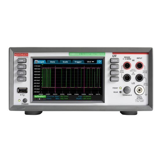
Contact information ..............1-2 Welcome The DMM6500 is a 6½ digit graphical sampling multimeter that expands standard DMM functions with high-speed digitizing and large graphical color touchscreen display. This manual provides information on completing verification and adjustment procedures for your DMM6500. -
Page 10: Extended Warranty
If you have any questions after you review the information in this documentation, please contact your local Keithley Instruments office, sales partner, or distributor. You can also call the Tektronix corporate headquarters (toll-free inside the U.S. and Canada only) at 1-800-833-9200. For worldwide contact numbers, visit tek.com/contact-us. -
Page 11: Performance Verification
Front-panel calibration verification ........... 2-6 Rear-panel verification ............2-46 Introduction Use the procedures in this section to verify that DMM6500 accuracy is within the limits stated in the instrument’s one-year accuracy specifications. Specifications and characteristics are subject to change without notice; refer to the Product Support and Downloads web page (tek.com/product-support) for the most recent specifications. -
Page 12: Verification Test Requirements
No direct airflow on the input terminals. Warmup period Allow the DMM6500 to warm up for at least 30 minutes before conducting the calibration verification procedures. If the instrument has been subjected to temperature extremes (more than 5 °C above or below T allow additional time for the internal temperature of the instrument to stabilize. -
Page 13: Line Power
Section 2: Performance verification Line power The DMM6500 requires a line voltage of 100 V to 240 V and a line frequency of 400 Hz, 50 Hz or 60 Hz. Calibration verification tests should be performed within this range. The instrument automatically senses the line frequency at power-up. -
Page 14: Calibration Verification Limits
Example reading limit calculation Assume you are testing the 10 V dc range using a 10 V input value. Using the DMM6500 one-year accuracy specification for 10 V dc of ± (25 ppm of reading + 5 ppm of range), the calculated limits are: Reading limits = 10 V ±... -
Page 15: Performing The Verification Test Procedures
DMM6500 6½-Digit Multimeter with Scanning Calibration and Adjustment Manual Section 2: Performance verification Performing the verification test procedures The following topics provide a summary of calibration verification test procedures and items to consider before performing any calibration verification test. Test summary Front-panel tests: •... -
Page 16: Test Considerations
Make sure the test equipment is set up for the proper function and range. • Do not connect test equipment to the DMM6500 through a scanner, multiplexer, or other switching equipment. The front and rear terminals of the instrument are rated for connection to circuits rated Measurement Category II up to 300 V, as described in International Electrotechnical Commission (IEC) Standard IEC 60664. - Page 17 Connect the shield to the output LO terminal of the calibrator. To verify dc voltage accuracy: 1. Use a low-thermal cable to connect the DMM6500 HI and LO INPUT terminals to the calibrator HI and LO terminals as shown in the following figure.
- Page 18 12. [Only for the 100 mV range] Select Rel Acquire. 13. Source positive and negative full-scale and half-scale voltages and allow for proper settling. 14. Select each range on the DMM6500, allow for proper settling, and verify the ranges according to the following tables.
- Page 19 DMM6500 6½-Digit Multimeter with Scanning Calibration and Adjustment Manual Section 2: Performance verification Verify the dc voltage 100 V range The information in this section is intended for qualified service personnel only, as described by the types of product users in the Safety precautions pages, provided at the beginning of this document.
-
Page 20: Ac Voltage Verification
AC voltage verification To verify ac voltage accuracy: • For the 100 mV to 100 V ranges, apply accurate voltages from the calibrator to the DMM6500 front-panel terminals. • For the 750 V range, connect the Fluke 5725A Amplifier to the calibrator. Apply accurate voltages from the calibrator terminals to the terminals on the front panel of the DMM6500. - Page 21 Section 2: Performance verification To verify ac voltage accuracy: 1. Connect the DMM6500 HI and LO INPUT connectors to the calibrator as shown in the following figure. Figure 2: Connections for ac voltage verification 100 mV to 100 V ranges 2.
- Page 22 Section 2: Performance verification DMM6500 6½-Digit Multimeter with Scanning Calibration and Adjustment Manual Verify the ac voltage 100 mV range Nominal value Frequency Lower limit Upper limit 20 Hz 99.91 100.09 1 kHz 99.91 100.09 50 kHz 99.83 100.17 100 kHz 99.32...
- Page 23 To verify ac voltage accuracy for the 750 V range: 1. Put the calibrator in Standby. 2. Connect the DMM6500 HI and LO INPUT connectors to the calibrator as shown in the following figure. 3. For 750 V at 50 kHz and 100 kHz outputs, connect the calibrator to the Fluke 5725A amplifier.
-
Page 24: Digitize Dc Voltage Verification
Apply accurate voltages from the calibrator to the terminals on the front panel of the DMM6500. • Verify that the displayed readings are within specified limits. Use the values in the tables following the steps below to verify the performance of the DMM6500. Actual values depend on the published specifications (see Example reading limit calculation (on page 2-4)). - Page 25 Section 2: Performance verification To verify digitize voltage accuracy: 1. Connect the DMM6500 HI and LO INPUT connectors to the calibrator as shown in the following figure. Figure 4: Connections for digitize voltage verification 100 mV to 1000 V ranges 2.
- Page 26 Section 2: Performance verification DMM6500 6½-Digit Multimeter with Scanning Calibration and Adjustment Manual Verify the digitize voltage 100 mV range Description Nominal value Lower limit Upper limit Full scale (+) 99.94 100.06 Half scale (+) 49.95 50.05 Half scale (–) -50.05...
-
Page 27: Frequency Verification
DMM6500. • Verify that the displayed readings are within specified limits. Use the values in the table following the steps below to verify the performance of the DMM6500. Actual values depend on the published specifications (see Example reading limit calculation (on page 2-4)). -
Page 28: Simulated Thermocouple Type J Temperature Verification
Simulated thermocouple Type J temperature verification To verify thermocouple accuracy, you will: • Apply accurate voltages from the calibrator to the terminals on the front panel of the DMM6500. • Verify that the displayed readings are within specified limits. Thermocouple accuracy is verified by using a dc voltage calibrator to output values from standard thermocouple tables available from the National Institute of Standards and Technology (NIST) or other sources. - Page 29 Section 2: Performance verification To verify the simulated thermocouple type J temperature: 1. Connect the DMM6500 HI and LO INPUT terminals to the calibrator HI and LO terminals as shown in the following figure. Figure 6: Connections for thermocouple verification DMM6500-905-01 Rev.
- Page 30 13. Allow five minutes for settling of the thermal voltage. 14. Record the measured offset voltage to 1 µV precision. If necessary, use the DMM6500 filter settings to reduce the noise of this measurement (for filter settings, go to MENU > Measure Calculations).
-
Page 31: Simulated Rtd Temperature Verification
Callendar-Van Dusen equation. To verify RTD temperature accuracy, you will: • Apply accurate resistance from the calibrator to the terminals on the front panel of the DMM6500. • Verify that the displayed readings are within specified limits. RTD equations The temperature versus resistance readings listed in the RTD reference tables are calculated using the Callendar-Van Dusen equation. - Page 32 Section 2: Performance verification DMM6500 6½-Digit Multimeter with Scanning Calibration and Adjustment Manual Equation for 0 °C to 850 °C temperature range (1 + AT + BT where: • is the calculated resistance of the RTD • is the known RTD resistance at 0 °C •...
- Page 33 DMM6500 6½-Digit Multimeter with Scanning Calibration and Adjustment Manual Section 2: Performance verification Verify the simulated RTD temperature Use the values in the tables following the steps below to verify the performance of the DMM6500. Actual values depend on the published specifications (see Example reading limit calculation (on page 2-4)).
- Page 34 Section 2: Performance verification DMM6500 6½-Digit Multimeter with Scanning Calibration and Adjustment Manual 2. For 3-wire accuracy, connect the DMM6500 INPUT and SENSE terminals to the calibrator as shown in the following figure. The SENSE HI wire is not required for 3-wire RTD measurements. For 3-wire RTD, accuracy is for <...
-
Page 35: Resistance Verification
238.6775 0.0218 0.2725 Resistance verification Use the following information to verify the performance of the DMM6500 resistance functions. Four-wire resistance verification To verify the 4-wire resistance function, you will: • Use shielded, Teflon-insulated or equivalent cables in a 4-wire configuration. - Page 36 Section 2: Performance verification DMM6500 6½-Digit Multimeter with Scanning Calibration and Adjustment Manual To verify 4-wire resistance accuracy: 1. Connect the DMM6500 INPUT and SENSE terminals to the calibrator as shown in the following figure. Figure 9: Connections for 4-wire resistance accuracy verification 2.
- Page 37 DMM6500 6½-Digit Multimeter with Scanning Calibration and Adjustment Manual Section 2: Performance verification You can use either the front-panel controls or remote interface commands to set measurement parameters for verification. For calibration, you must use remote interface commands. The example below is an example of remote interface commands that will generate event messages.
- Page 38 • Use shielded, Teflon-insulated or equivalent cables in a 2-wire configuration. • Apply accurate resistance from the calibrator to the terminals on the front panel of the DMM6500. • Verify that the displayed readings are within specified limits. Verify resistance 100 MΩ range To verify the 100 MΩ...
- Page 39 Figure 10: Connections for 100 MΩ verification 2. Set the calibrator for 2-wire resistance with external sense off. 3. On the DMM6500, press the FUNCTION key and select 2W Res. 4. On the home screen, select the button next to Range and select 100 MΩ.
-
Page 40: Dc Current Verification
To verify the DMM6500 specifications with zero input current, disconnect all cables and calibrators from the DMM6500 input. This is a separate setup from that used in the procedure below for mid-scale and full-scale readings. - Page 41 Section 2: Performance verification To prepare the DMM6500 for dc current accuracy verification: 1. Set up the DMM6500 for dc current and the range being tested. Make sure relative offset is disabled. 2. Connect the calibrator, DMM6500, and reference DMM as shown in the following figure.
- Page 42 Model 8508A or 8588A 200 µA range to verify the DMM6500 10 µA and 100 µA ranges. Use the Model 8508A or 8588A 2 mA, 20 mA, and 200 mA ranges to verify the DMM6500 1 mA, 10 mA, and 100 mA ranges, respectively.
- Page 43 Verify that the displayed readings are within specified limits. To verify dc current accuracy: 1. Set up the DMM6500 for dc current and the range being tested. Make sure that relative offset is disabled. 2. Connect the DMM6500 and calibrator as shown in the following figure.
- Page 44 Section 2: Performance verification DMM6500 6½-Digit Multimeter with Scanning Calibration and Adjustment Manual Zero verify the DMM6500: 1. On the calibrator, select the OPR/STBY key. Make sure that the front panel displays STANDBY. 2. Set the ranges to 100 mA.
-
Page 45: Digitize Current Verification
DMM6500 6½-Digit Multimeter with Scanning Calibration and Adjustment Manual Section 2: Performance verification Digitize current verification The following topics describe how to verify digitized dc current on the DMM6500. Verify digitize current 100 µA to 3 A ranges To verify digitize dc current accuracy: 1. - Page 46 Section 2: Performance verification DMM6500 6½-Digit Multimeter with Scanning Calibration and Adjustment Manual Verify digitize current 100 µA range Description Calibrator setpoint Lower limit Upper limit Full scale (+) 99.998 99.878 100.118 Half scale (+) 49.9991 49.9141 50.0841 Half scale (–) -49.993...
-
Page 47: Ac Current Verification
DMM6500 6½-Digit Multimeter with Scanning Calibration and Adjustment Manual Section 2: Performance verification Verify digitize current 1 A range Description Calibrator setpoint Lower limit Upper limit Full scale (+) 0.999 1.001 Half scale (+) 0.49935 0.50065 Half scale (–) –0.5 -0.50065... - Page 48 • Verify that the displayed readings fall within specified limits. Use the values in the following tables to verify the performance of the DMM6500. Actual values depend on the published specifications (see Example reading limit calculation (on page 2-4)).
- Page 49 DMM6500 6½-Digit Multimeter with Scanning Calibration and Adjustment Manual Section 2: Performance verification 7. Connect the DMM6500 to the calibrator as shown in the following figure. Figure 14: Connections for ac current verification 8. Source ac current for each of the frequencies listed in the following tables.
- Page 50 Section 2: Performance verification DMM6500 6½-Digit Multimeter with Scanning Calibration and Adjustment Manual Verify ac current 100 mA range Description Verification point Lower limit Upper limit 100 mA at 40 Hz 99.86 100.14 100 mA at 1 kHz 99.86 100.14 100 mA at 4.9 kHz...
-
Page 51: Capacitance Verification
To compensate for capacitance offset of the cable and 1 µF thru 100 µF decade box: 1. Connect the DMM6500, shielded banana cable, banana to dual BNC cable, and 1 µF through 100 µF decade capacitor box as shown in the following diagram. - Page 52 Section 2: Performance verification DMM6500 6½-Digit Multimeter with Scanning Calibration and Adjustment Manual 2. Set the decade capacitor box to 0 F. 3. On the DMM6500, press the FUNCTION key, select the Measure Functions tab, and select Capacitance. 4. Press the MENU key.
- Page 53 DMM6500 6½-Digit Multimeter with Scanning Calibration and Adjustment Manual Section 2: Performance verification 9. Connect the shielded banana cable to the 1 nF to 1 µF Decade Capacitance Box as shown in the figure below. Figure 16: Capacitance verification connections 10.
-
Page 54: Verifying Zero Values Using A 4-Wire Short
Four-wire short verifications are not included in the Customer Calibration Data Report. To verify zero values using a 4-wire short, you will: • Check the zero values of various test points with 4-wire connections to the DMM6500 front or rear terminals. •... - Page 55 DMM6500 6½-Digit Multimeter with Scanning Calibration and Adjustment Manual Section 2: Performance verification Verify resistance zero values using a 4-wire short To verify resistance zero values: 1. Select the 4W Res function. 2. Set the DMM6500 to the 1Ω range.
-
Page 56: Rear-Panel Verification
Section 2: Performance verification DMM6500 6½-Digit Multimeter with Scanning Calibration and Adjustment Manual Verify dc voltage zero values using the 4-wire short To verify dc voltage zero values: 1. Leave the short connected as described in Verify resistance zero values using a 4-wire short page 2-45). -
Page 57: Dc Current 10 A Range Verification
3. Press the HOME key. 4. Set the range to 10A. 5. Connect the DMM6500, reference DMM, calibrator, and amplifier as shown in the following figure. Ensure cabling is designed to conduct 10 A without significant voltage drop. In general, cables for the 10 A range steps should be made of heavy gauge wire and should be as short as practical. - Page 58 Section 2: Performance verification DMM6500 6½-Digit Multimeter with Scanning Calibration and Adjustment Manual Apply a relative offset to the DMM6500: 1. On the calibrator, select the OPR/STBY key. Ensure that the front panel displays STANDBY. 2. Verify the DMM6500 zero reading.
-
Page 59: Digitize Current 10 A Range Verification
10 A range steps should be made of heavy gauge wire and should be as short as practical. To verify the 10 A range: 1. Connect DMM6500, calibrator, and amplifier as shown in the following figure. Figure 19: Connections for the 10 A range DMM6500-905-01 Rev. E June 2021... - Page 60 Section 2: Performance verification DMM6500 6½-Digit Multimeter with Scanning Calibration and Adjustment Manual 2. Set the TERMINALS switch to REAR. 3. Press the FUNCTION key, select the Digitize Functions tab, and select Digitize Current. 4. Press the HOME key. 5. Set the range to 10A.
-
Page 61: Ac Current 10 A Verification
AC current 10 A verification Verify that the displayed readings are within specified limits. Use the values in the tables following the steps below to verify the performance of the DMM6500. Actual values depend on the published specifications (see Example reading limit calculation (on page 2-4)). - Page 62 Section 2: Performance verification DMM6500 6½-Digit Multimeter with Scanning Calibration and Adjustment Manual 8. Connect the DMM6500 to the calibrator and amplifier as shown in the following figure. Ensure cabling is designed to conduct 10 A without significant voltage drop. In general, cables for the 10 A range steps should be made of heavy gauge wire and should be as short as practical.
- Page 63 DMM6500 6½-Digit Multimeter with Scanning Calibration and Adjustment Manual Section 2: Performance verification Verify ac current 10 A range Description Verification point Lower limit Upper limit 40 Hz 9.954 10.046 1 kHz 9.954 10.046 4.9 kHz 9.954 10.046 DMM6500-905-01 Rev. E June 2021...
-
Page 65: Adjustment
Use the procedures in this section to adjust the DMM6500 calibration. DMM6500 performance is specified for a period of 90 days, 1 year, or 2 years from adjustment. Adjustment should be performed at one of these intervals, depending on your specification requirements. -
Page 66: Environmental Conditions
No direct airflow on the input terminals. Line power The DMM6500 requires a line voltage of 100 V to 240 V and a line frequency of 400 Hz, 50 Hz or 60 Calibration adjustments should be performed within this range. -
Page 67: Adjustment Overview
Processor (TSP ) command language. There is no front-panel method for full adjustment. You can use the Keithley Test Script Builder to send you adjustment commands. See "Test Script Builder (TSB)" in the Model DMM6500 Reference Manual (DMM6500-901-01). To use GPIB with your DMM6500, you must use the KTTI-GPIB Communication and Digital I/O Accessory. -
Page 68: General Adjustment Considerations
• The Keithley Models 8610 and 8620 4-wire shorts connect all four terminals electrically, but the layout of the board traces makes DMM6500 adjustment sensitive to their orientation. Note the HI/LO terminal markings and be sure to insert connections in the correct orientation. Note that the DMM6500 rear input terminals are rotated 90°... -
Page 69: Initial Instrument Setup
You must also unlock calibration. Select the correct terminals On the DMM6500, you must adjust calibration from both the front and rear terminals. You can verify calibration on either the front or rear terminals. To set the instrument to the rear-panel terminals, press the TERMINALS switch on the front panel of the instrument. -
Page 70: Verify Instrument Date And Time
For detail on remote communications, refer to the DMM6500 Reference Manual section "Remote communications interfaces." Calibration adjustment is performed by connecting reference signals to the DMM6500 and sending a series of adjustment commands using one of the remote interfaces. The adjustment procedure may be done interactively, programmatically, or using a combination of the two. -
Page 71: Disable Temperature Correction
The front-panel display does not show calibration progress or completion. The following sections provide the preparation and command parameters that you need to complete adjustments to you DMM6500. The preparation sections provide information necessary for making connections and other equipment needed for that adjustment. The command parameter tables are meant to run through in any order allowing you to adjust just the parameters you need. - Page 72 To prepare the DMM6500 for a front-terminal adjustment with a 4-wire short: 1. Set the TERMINALS switch to FRONT. 2. Install the Keithley Model 8610 or 8620 shorting plug on the front terminals of the DMM6500 as shown in the figure below.
- Page 73 Command parameters for a front-terminal adjustment with a 4-wire short When calibrating your DMM6500 for a front-terminal adjustment with a 4-wire short, use the following command parameters. Send each command parameter twice. First, send the parameter using the setup command. Second, send the parameter using the execute command.
-
Page 74: Rear-Terminal Adjustment With A 4-Wire Short
Section 3: Adjustment DMM6500 6½-Digit Multimeter with Scanning Calibration and Adjustment Manual cal_3W_100kohm_SLO_zero_front cal_4W_100kohm_zero_front cal_2W_1Mohm_zero_front cal_4W_1Mohm_zero_front cal_2W_HiOhm_zero_front cal_4W_HiOhm_zero_front cal_4W_HiOhm_zero_sense cal_diode_10mA_zero_front cal_diode_1mA_zero_front cal_diode_100uA_zero_front cal_diode_10uA_zero_front cal_ACV_1V_zero cal_ACV_10V_zero Rear-terminal adjustment with a 4-wire short The following procedure provides instructions for completing a rear-terminal adjustment using a 4-wire short. - Page 75 To prepare the DMM6500 for rear-terminal adjustment: 1. Set the TERMINALS switch to REAR. 2. Install the Keithley Model 8610 or 8620 shorting plug on the rear terminals of the DMM6500 as shown in the figure below. The shorting plug terminals must be connected so that HI and LO are correctly aligned. Zero accuracy will be affected if the shorting plug terminals are not aligned correctly.
- Page 76 Command parameters for a rear-terminal adjustment with a 4-wire short When calibrating your DMM6500 for a rear-terminal adjustment with a 4-wire short, use the following command parameters. Send each command parameter twice. First, send the parameter using the setup command. Second, send the parameter using the execute command.
-
Page 77: Front-Terminal Adjustment With Open Circuit Inputs
Prepare your DMM6500 for a front-terminal adjustment with open circuit inputs To prepare the DMM6500 for a front-terminal adjustment with open circuit inputs: 1. Set the TERMINALS switch to FRONT. 2. Remove all connections from the front terminals of your DMM6500. -
Page 78: Rear-Terminal Adjustment With Open Circuit Inputs
Command parameters for a front-terminal adjustment with open circuit inputs When calibrating your DMM6500 for a front-terminal adjustment with open circuit inputs, use the following command parameters. Send each command parameter twice. First, send the parameter using the setup command. Second, send the parameter using the execute command. -
Page 79: Resistance Adjustment
Command parameters for a rear-terminal adjustment with open circuit inputs When calibrating your DMM6500 for a rear-terminal adjustment with open circuit inputs, use the following command parameters. Send each command parameter twice. First, send the parameter using the setup command. Second, send the parameter using the execute command. - Page 80 To prepare the DMM6500 for a front-terminal adjustment: 1. Set the TERMINALS switch to FRONT. 2. Connect the DMM6500 to the calibrator as shown in the following figure. Figure 23: Connection for a resistance accuracy adjustment 3. Allow the instruments and cables to settle for five minutes.
- Page 81 DMM6500 6½-Digit Multimeter with Scanning Calibration and Adjustment Manual Section 3: Adjustment Command parameters for a resistance adjustment When calibrating your DMM6500 for a resistance adjustment, use the following command parameters. Send each command parameter twice. First, send the parameter using the setup command. Second, send the parameter using the execute command along with the calibrator stimulus value.
-
Page 82: Dc Voltage Adjustment
Section 3: Adjustment DMM6500 6½-Digit Multimeter with Scanning Calibration and Adjustment Manual Command parameters Calibrator Calibrator Calibrator Reference DMM dc function range value current range cal_TS7 4-wire Ω cal_4W_10ohm_fs actual from calibrator 4-wire Ω cal_4W_10ohm_OCOMP_fs actual from calibrator 4-wire Ω... - Page 83 Prepare your DMM6500 for a dc voltage adjustment To prepare the DMM6500 for a dc voltage adjustment: 1. Connect a cable between the calibrator and the DMM6500 as shown in the figure below. Figure 24: Connection for a dc voltage accuracy adjustment 2.
-
Page 84: Dc Current Adjustment
DMM6500 6½-Digit Multimeter with Scanning Calibration and Adjustment Manual Command parameters for a dc voltage adjustment When calibrating your DMM6500 for a dc voltage adjustment, use the following command parameters. Send each command parameter twice. First, send the parameter using the setup command. Second, send the parameter using the execute command. - Page 85 Prepare your DMM6500 for a dc current adjustment To prepare the DMM6500 for dc current adjustment: Connect the Model DMM6500 to the calibrator as shown in the following figure. Figure 25: Connection for dc current DMM6500-905-01 Rev. E June 2021...
- Page 86 DMM6500 6½-Digit Multimeter with Scanning Calibration and Adjustment Manual Command parameters for a dc current adjustment When calibrating your DMM6500 for a dc current adjustment, use the following command parameters. Send each command parameter twice. First, send the parameter using the setup command. Second, send the parameter using the execute command along with the calibrator stimulus value.
- Page 87 DMM6500 6½-Digit Multimeter with Scanning Calibration and Adjustment Manual Section 3: Adjustment Command parameters Calibrator Calibrator Calibrator Calibrator Reference function range value stimulus value* DMM dc current range cal_TS6 10 µA range (+) full scale nominal cal_DCI_10uA_fs_pos dc current 0.00022 0.00001...
-
Page 88: Dc Current 10 A Range Adjustment
Section 3: Adjustment DMM6500 6½-Digit Multimeter with Scanning Calibration and Adjustment Manual 10 mA range (-) full scale nominal cal_DCI_10mA_fs_neg dc current 0.022 -0.01 8508A or 8588A 10 mA Reading cal_DCI_DIGI_10mA_fs_neg dc current 0.022 -0.01 8508A or 8588A 10 mA... - Page 89 Prepare your DMM6500 for a dc current 10 A range adjustment To prepare the DMM6500 for dc current adjustment for the 10 A range: Connect the DMM6500 to the calibrator as shown in the following figure using 10 A cables. Figure 26: Connection for a 10 A range adjustment DMM6500-905-01 Rev.
-
Page 90: Ac Voltage Adjustment
DMM6500 6½-Digit Multimeter with Scanning Calibration and Adjustment Manual Command parameters for a dc current 10 A range adjustment When calibrating your DMM6500 for a dc current 10 A range adjustment, use the following command parameters. Connect a 10 A cable for this adjustment. - Page 91 Figure 27: Connection for an ac voltage adjustment 3. Allow the instrument and cables to settle for 30 seconds. 4. On the calibrator, source 10 mV 1.0 kHz and allow the calibrator and DMM6500 to settle properly. 5. Enable the OPR key.
- Page 92 DMM6500 6½-Digit Multimeter with Scanning Calibration and Adjustment Manual Command parameters for an ac voltage adjustment When calibrating your DMM6500 for an ac voltage adjustment, use the following command parameters. Send each command parameter twice. First, send the parameter using the setup command. Second, send the parameter using the execute command.
-
Page 93: Ac Current Adjustment
Prepare your DMM6500 for an ac current adjustment To prepare the DMM6500 for an ac current adjustment: Connect the Model DMM6500 to the calibrator as shown in the following figure. Figure 28: Connection for ac current DMM6500-905-01 Rev. E June 2021... - Page 94 DMM6500 6½-Digit Multimeter with Scanning Calibration and Adjustment Manual Command parameters for an ac current adjustment When calibrating your DMM6500 for an ac current adjustment, use the following command parameters. Send each command parameter twice. First, send the parameter using the setup command. Second, send the parameter using the execute command.
-
Page 95: Ac Current 10 A Range Adjustment
Prepare your DMM6500 for an ac current 10 A range adjustment To prepare the DMM6500 for an ac current adjustment in the 10 A range: Connect the DMM6500 to the calibrator as shown in the following figure using 10 A cables. Figure 29: Connection for a 10 A range adjustment DMM6500-905-01 Rev. -
Page 96: Frequency Adjustment
DMM6500 6½-Digit Multimeter with Scanning Calibration and Adjustment Manual Command parameters for an ac current 10 A range adjustment When calibrating your DMM6500 for an ac current 10 A range adjustment, use the following command parameters. Send each command parameter twice. First, send the parameter using the setup command. Second, send the parameter using the execute command. - Page 97 Prepare your DMM6500 for a frequency adjustment To prepare the DMM6500 for a frequency adjustment: 1. Connect the Keithley Instruments Model 3390 function generator to the DMM6500 INPUT HI and LO terminals as shown in the following figure. 2. Use the BNC to banana adapter at the UUT connection.
-
Page 98: Complete List Of Calibration Commands
Complete list of calibration commands To make your adjustment procedure easier, you can copy and paste the code examples below into the Keithley Test Script Builder (TSB software). The commands can be copied and pasted two lines at a time. - Page 99 DMM6500 6½-Digit Multimeter with Scanning Calibration and Adjustment Manual Section 3: Adjustment -- Use front-terminal 4-wire short setup cal.adjust.step.setup("cal_DCV_100mV_zero_front") cal.adjust.step.execute("cal_DCV_100mV_zero_front") -- Use front-terminal 4-wire short setup cal.adjust.step.setup("cal_DCV_DIGI_100mV_zero") cal.adjust.step.execute("cal_DCV_DIGI_100mV_zero") -- Use front-terminal 4-wire short setup cal.adjust.step.setup("cal_DCV_1V_zero_front") cal.adjust.step.execute("cal_DCV_1V_zero_front") -- Use front-terminal 4-wire short setup cal.adjust.step.setup("cal_DCV_DIGI_1V_zero")
- Page 100 Section 3: Adjustment DMM6500 6½-Digit Multimeter with Scanning Calibration and Adjustment Manual -- Use front-terminal 4-wire short setup cal.adjust.step.setup("cal_3W_1kohm_SLO_zero_front") cal.adjust.step.execute("cal_3W_1kohm_SLO_zero_front") -- Use front-terminal 4-wire short setup cal.adjust.step.setup("cal_4W_1kohm_zero_front") cal.adjust.step.execute("cal_4W_1kohm_zero_front") -- Use front-terminal 4-wire short setup cal.adjust.step.setup("cal_2W_10kohm_zero_front") cal.adjust.step.execute("cal_2W_10kohm_zero_front") -- Use front-terminal 4-wire short setup cal.adjust.step.setup("cal_3W_10kohm_zero_front")
- Page 101 DMM6500 6½-Digit Multimeter with Scanning Calibration and Adjustment Manual Section 3: Adjustment -- Use front-terminal 4-wire short setup cal.adjust.step.setup("cal_ACV_10V_zero") cal.adjust.step.execute("cal_ACV_10V_zero") -- Use rear-terminal 4-wire short setup cal.adjust.step.setup("cal_DCV_100mV_zero_rear") cal.adjust.step.execute("cal_DCV_100mV_zero_rear") -- Use rear-terminal 4-wire short setup cal.adjust.step.setup("cal_DCV_100mV_zero_rear") cal.adjust.step.execute("cal_DCV_100mV_zero_rear") -- Use rear-terminal 4-wire short setup cal.adjust.step.setup("cal_DCV_1V_zero_rear")
- Page 102 Section 3: Adjustment DMM6500 6½-Digit Multimeter with Scanning Calibration and Adjustment Manual -- Use rear-terminal 4-wire short setup cal.adjust.step.setup("cal_3W_10kohm_SLO_zero_rear") cal.adjust.step.execute("cal_3W_10kohm_SLO_zero_rear") -- Use rear-terminal 4-wire short setup cal.adjust.step.setup("cal_4W_10kohm_zero_rear") cal.adjust.step.execute("cal_4W_10kohm_zero_rear") -- Use rear-terminal 4-wire short setup cal.adjust.step.setup("cal_2W_100kohm_zero_rear") cal.adjust.step.execute("cal_2W_100kohm_zero_rear") -- Use rear-terminal 4-wire short setup cal.adjust.step.setup("cal_3W_100kohm_SLO_zero_rear")
- Page 103 DMM6500 6½-Digit Multimeter with Scanning Calibration and Adjustment Manual Section 3: Adjustment -- Use front-terminal 4-wire open circuit setup cal.adjust.step.setup("cal_DCI_10uA_zero_front") cal.adjust.step.execute("cal_DCI_10uA_zero_front") -- Use front-terminal 4-wire open circuit setup cal.adjust.step.setup("cal_DCI_DIGI_3A_zero") cal.adjust.step.execute("cal_DCI_DIGI_3A_zero") -- Use front-terminal 4-wire open circuit setup cal.adjust.step.setup("cal_DCI_DIGI_1A_zero") cal.adjust.step.execute("cal_DCI_DIGI_1A_zero") -- Use front-terminal 4-wire open circuit setup cal.adjust.step.setup("cal_DCI_DIGI_100mA_zero")
- Page 104 Section 3: Adjustment DMM6500 6½-Digit Multimeter with Scanning Calibration and Adjustment Manual -- Use rear-terminal 4-wire open circuit setup cal.adjust.step.setup("cal_DCI_10uA_zero_rear") cal.adjust.step.execute("cal_DCI_10uA_zero_rear") -- Use resistance setup cal.adjust.step.setup("cal_TS7") cal.adjust.step.execute("cal_TS7") -- Use resistance setup cal.adjust.step.setup("cal_4W_10ohm_fs") cal.adjust.step.execute("cal_4W_10ohm_fs", 10ohm_value_read_from_calibrator) -- Use resistance setup cal.adjust.step.setup("cal_4W_10ohm_OCOMP_fs") cal.adjust.step.execute("cal_4W_10ohm_OCOMP_fs", 10ohm_value_read_from_calibrator) -- Use resistance setup cal.adjust.step.setup("cal_4W_100ohm_fs")
- Page 105 DMM6500 6½-Digit Multimeter with Scanning Calibration and Adjustment Manual Section 3: Adjustment cal.adjust.step.setup("cal_DCV_DIGI_1kV_fs_pos") cal.adjust.step.setup("cal_DCV_DIGI_1kV_fs_pos") -- Use dc voltage setupcal.adjust.step.setup("cal_DCV_DIGI_1kV_fs_neg") cal.adjust.step.setup("cal_DCV_DIGI_1kV_fs_neg") -- Use dc voltage setup cal.adjust.step.setup("cal_DCV_100V_fs_pos") cal.adjust.step.setup("cal_DCV_100V_fs_pos") -- Use dc voltage setup cal.adjust.step.setup("cal_DCV_DIGI_100V_fs_pos") cal.adjust.step.setup("cal_DCV_DIGI_100V_fs_pos") -- Use dc voltage setup cal.adjust.step.setup("cal_DCV_100V_fs_neg") cal.adjust.step.setup("cal_DCV_100V_fs_neg")
- Page 106 Section 3: Adjustment DMM6500 6½-Digit Multimeter with Scanning Calibration and Adjustment Manual cal.adjust.step.execute("cal_DCI_DIGI_100uA_fs_pos",value_read_from_ 8508A/8588A) -- Use dc current setup cal.adjust.step.setup("cal_DCI_100uA_fs_neg") cal.adjust.step.execute("cal_DCI_100uA_fs_neg",value_read_from_ 8508A/8588A) -- Use dc current setup cal.adjust.step.setup("cal_DCI_DIGI_100uA_fs_neg") cal.adjust.step.execute("cal_DCI_DIGI_100uA_fs_neg",value_read_from_ 8508A/8588A) -- Use dc current setup cal.adjust.step.setup("cal_DCI_1mA_fs_pos") cal.adjust.step.execute("cal_DCI_1mA_fs_pos",value_read_from_ 8508A/8588A) -- Use dc current setup cal.adjust.step.setup("cal_DCI_DIGI_1mA_fs_pos")
- Page 107 DMM6500 6½-Digit Multimeter with Scanning Calibration and Adjustment Manual Section 3: Adjustment cal.adjust.step.execute("cal_DCI_DIGI_1A_fs_neg") -- Use dc current setup cal.adjust.step.setup("cal_DCI_DIGI_3A_fs_pos") cal.adjust.step.execute("cal_DCI_DIGI_3A_fs_pos") -- Use dc current setup cal.adjust.step.setup("cal_DCI_DIGI_3A_fs_neg") cal.adjust.step.execute("cal_DCI_DIGI_3A_fs_neg") -- Use dc current 10 A setup cal.adjust.step.setup("cal_DCI_10A_fs_pos") cal.adjust.step.execute("cal_DCI_10A_fs_pos") -- Use dc current 10 A setup cal.adjust.step.setup("cal_DCI_DIGI_10A_fs_pos")
- Page 108 Section 3: Adjustment DMM6500 6½-Digit Multimeter with Scanning Calibration and Adjustment Manual cal.adjust.step.execute"cal_ACV_1V_200kHz_fs") -- Use ac voltage setup cal.adjust.step.setup("cal_ACV_1V_300kHz_fs") cal.adjust.step.execute("cal_ACV_1V_300kHz_fs") -- Use ac voltage setup cal.adjust.step.setup("cal_ACV_10V_1kHz_1pct") cal.adjust.step.execute("cal_ACV_10V_1kHz_1pct") -- Use ac voltage setup cal.adjust.step.setup("cal_ACV_10V_10Hz_fs") cal.adjust.step.execute("cal_ACV_10V_10Hz_fs") -- Use ac voltage setup cal.adjust.step.setup("cal_ACV_10V_1kHz_fs") cal.adjust.step.execute("cal_ACV_10V_1kHz_fs")
- Page 109 DMM6500 6½-Digit Multimeter with Scanning Calibration and Adjustment Manual Section 3: Adjustment cal.adjust.step.execute("cal_ACV_700V_100kHz_1pct") -- Use ac voltage setup cal.adjust.step.setup("cal_ACV_700V_200kHz_1pct") cal.adjust.step.execute("cal_ACV_700V_200kHz_1pct") -- Use ac voltage setup cal.adjust.step.setup("cal_ACV_700V_300kHz_1pct") cal.adjust.step.execute("cal_ACV_700V_300kHz_1pct") -- Use ac voltage setup cal.adjust.step.setup("cal_ACV_700V_1kHz_fs") cal.adjust.step.execute("cal_ACV_700V_1kHz_fs") -- Use ac current setup cal.adjust.step.setup("cal_ACI_100uA_1kHz_tenth") cal.adjust.step.execute("cal_ACI_100uA_1kHz_tenth")
-
Page 110: Enable Temperature Correction
Section 3: Adjustment DMM6500 6½-Digit Multimeter with Scanning Calibration and Adjustment Manual cal.adjust.step.execute("cal_ACI_1A_1kHz_fs") -- Use ac current setup cal.adjust.step.setup("cal_ACI_3A_1kHz_tenth") cal.adjust.step.execute("cal_ACI_3A_1kHz_tenth") -- Use ac current setup cal.adjust.step.setup("cal_ACI_3A_1kHz_fs") cal.adjust.step.execute("cal_ACI_3A_1kHz_fs")<CT6500_only_start> -- Use ac current 10 A setup cal.adjust.step.setup("cal_ACI_10A_400Hz_tenth") cal.adjust.step.execute("cal_ACI_10A_400Hz_tenth") -- Use ac current 10 A setup cal.adjust.step.setup("cal_ACI_10A_400Hz_fs") -
Page 111: Setting Time, Adjustment, And Verification Dates
= os.time({year = 2018, month = 1, day = 9}) The cal.verify.date command is used to record the date of the last verification that was done independently of DMM6500 adjustment. Typically, this date is set at the completion of a performance verification procedure. -
Page 112: Handling Events
DMM6500 6½-Digit Multimeter with Scanning Calibration and Adjustment Manual Once the reference signal is stable, sending the calibration adjustment command initiates internal measurement operations in the DMM6500. These steps can take from a few seconds to 30 seconds to complete. -
Page 113: Tsp Command Reference
Section 4 TSP command reference In this section: TSP commands ................ 4-1 TSP commands The TSP commands available for the instrument are listed in alphabetical order. Introduction This section contains detailed information on the DMM6500 remote calibration commands. -
Page 114: Cal.adjust.count
Section 4: TSP command reference DMM6500 6½-Digit Multimeter with Scanning Calibration and Adjustment Manual cal.adjust.count This attribute returns the number of times the instrument has been adjusted. Type TSP-Link accessible Affected by Where saved Default value Attribute (R) Not applicable... -
Page 115: Cal.adjust.date
DMM6500 6½-Digit Multimeter with Scanning Calibration and Adjustment Manual Section 4: TSP command reference cal.adjust.date This attribute contains the date when the instrument was last adjusted. Type TSP-Link accessible Affected by Where saved Default value Attribute (RW) Not applicable Nonvolatile memory... -
Page 116: Cal.adjust.step.setup()
Section 4: TSP command reference DMM6500 6½-Digit Multimeter with Scanning Calibration and Adjustment Manual cal.adjust.step.setup() This function sets up the specified adjustment step. Type TSP-Link accessible Affected by Where saved Default value Function Usage cal.adjust.step.setup(stepname) cal.adjust.step.setup(stepname, value) stepname The adjustment step to start value The value for this adjustment step. -
Page 117: Cal.adjust.step.execute()
DMM6500 6½-Digit Multimeter with Scanning Calibration and Adjustment Manual Section 4: TSP command reference cal.adjust.step.execute() This function executes the specified adjustment step. Type TSP-Link accessible Affected by Where saved Default value Function Usage cal.adjust.step.execute(stepname) cal.adjust.step.execute(stepname, value) stepname The adjustment step to start value Value for this adjustment step. -
Page 118: Cal.lock()
Section 4: TSP command reference DMM6500 6½-Digit Multimeter with Scanning Calibration and Adjustment Manual cal.lock() This function prevents access to instrument calibration. Type TSP-Link accessible Affected by Where saved Default value Function Usage cal.lock() Details Calibration data is locked during normal operation. To perform calibration, you must unlock calibration. -
Page 119: Cal.password
DMM6500 6½-Digit Multimeter with Scanning Calibration and Adjustment Manual Section 4: TSP command reference cal.password This attribute sets the password that you send when you unlock calibration. Type TSP-Link accessible Affected by Where saved Default value Attribute (W) Not applicable... -
Page 120: Cal.save()
Section 4: TSP command reference DMM6500 6½-Digit Multimeter with Scanning Calibration and Adjustment Manual cal.save() This function saves the calibration constants. Type TSP-Link accessible Affected by Where saved Default value Function Usage cal.save() Details This command stores the internally calculated calibration constants that were derived during the comprehensive calibration procedure. -
Page 121: Cal.unlock()
DMM6500 6½-Digit Multimeter with Scanning Calibration and Adjustment Manual Section 4: TSP command reference cal.unlock() This attribute unlocks calibration operations. Type TSP-Link accessible Affected by Where saved Default value Function Usage cal.unlock("password") password A string containing the password to unlock calibration Details Calibration data is locked during normal operation. -
Page 122: Cal.verify.date
Section 4: TSP command reference DMM6500 6½-Digit Multimeter with Scanning Calibration and Adjustment Manual cal.verify.date This attribute contains the date of the last calibration verification. Type TSP-Link accessible Affected by Where saved Default value Attribute (RW) Not applicable Nonvolatile memory... - Page 123 DMM6500 6½-Digit Multimeter with Scanning Calibration and Adjustment Manual Section 4: TSP command reference Example 1 cal.verify.date = os.time({year=2018, month=9, day=5}) print(cal.verify.date) Set the verify calibration date to September 5, 2018. Verify the date. Example output: Sep 5 2014 12:00:00.000 Example 2 cal.verify.date = os.time()
Need help?
Do you have a question about the DMM6500 and is the answer not in the manual?
Questions and answers