Keithley DMM7510 User Manual
7 1/2 digit graphical sampling multimeter
Hide thumbs
Also See for DMM7510:
- Reference manual (1036 pages) ,
- Calibration manual (142 pages) ,
- Quick start manual (27 pages)
Table of Contents
Advertisement
Model DMM7510
7½ Digit Graphical Sampling Multimeter
User's Manual
DMM7510-900-01 Rev. B / May 2015
The following safety precautions should be observed before using this product and any associated instrumentation. Although
some instruments and accessories would normally be used with nonhazardous voltages, there are situations where hazardous
conditions may be present.
This product is intended for use by qualified personnel who recognize shock hazards and are familiar with the safety precautions
required to avoid possible injury. Read and follow all installation, operation, and maintenance information carefully before using
the product. Refer to the user documentation for complete product specifications.
If the product is used in a manner not specified, the protection provided by the product warranty may be impaired.
The types of product users are:
Responsible body is the individual or group responsible for the use and maintenance of equipment, for ensuring that the
equipment is operated within its specifications and operating limits, and for ensuring that operators are adequately trained.
Operators use the product for its intended function. They must be trained in electrical safety procedures and proper use of the
instrument. They must be protected from electric shock and contact with hazardous live circuits.
Maintenance personnel perform routine procedures on the product to keep it operating properly, for example, setting the line
voltage or replacing consumable materials. Maintenance procedures are described in the user documentation. The procedures
explicitly state if the operator may perform them. Otherwise, they should be performed only by service personnel.
Service personnel are trained to work on live circuits, perform safe installations, and repair products. Only properly trained
service personnel may perform installation and service procedures.
Keithley Instruments products are designed for use with electrical signals that are measurement, control, and data I/O
connections, with low transient overvoltages, and must not be directly connected to mains voltage or to voltage sources with high
transient overvoltages. Measurement Category II (as referenced in IEC 60664) connections require protection for high transient
overvoltages often associated with local AC mains connections. Certain Keithley measuring instruments may be connected to
mains. These instruments will be marked as category II or higher.
Unless explicitly allowed in the specifications, operating manual, and instrument labels, do not connect any instrument to mains.
Exercise extreme caution when a shock hazard is present. Lethal voltage may be present on cable connector jacks or test
fixtures. The American National Standards Institute (ANSI) states that a shock hazard exists when voltage levels greater than
30 V RMS, 42.4 V peak, or 60 VDC are present. A good safety practice is to expect that hazardous voltage is present in any
unknown circuit before measuring.
Operators of this product must be protected from electric shock at all times. The responsible body must ensure that operators
are prevented access and/or insulated from every connection point. In some cases, connections must be exposed to potential
human contact. Product operators in these circumstances must be trained to protect themselves from the risk of electric shock. If
the circuit is capable of operating at or above 1000 V, no conductive part of the circuit may be exposed.
Do not connect switching cards directly to unlimited power circuits. They are intended to be used with impedance-limited
sources. NEVER connect switching cards directly to AC mains. When connecting sources to switching cards, install protective
devices to limit fault current and voltage to the card.
Before operating an instrument, ensure that the line cord is connected to a properly-grounded power receptacle. Inspect the
connecting cables, test leads, and jumpers for possible wear, cracks, or breaks before each use.
When installing equipment where access to the main power cord is restricted, such as rack mounting, a separate main input
power disconnect device must be provided in close proximity to the equipment and within easy reach of the operator.
For maximum safety, do not touch the product, test cables, or any other instruments while power is applied to the circuit under
test. ALWAYS remove power from the entire test system and discharge any capacitors before: connecting or disconnecting
cables or jumpers, installing or removing switching cards, or making internal changes, such as installing or removing jumpers.
Do not touch any object that could provide a current path to the common side of the circuit under test or power line (earth)
ground. Always make measurements with dry hands while standing on a dry, insulated surface capable of withstanding the
voltage being measured.
北京海洋兴业科技股份有限公司(证券代码:839145)
For safety, instruments and accessories must be used in accordance with the operating instructions. If the instruments or
Safety precautions
电话:010-62176775
网址:www.hyxyyq.com
Advertisement
Table of Contents

Related Manuals for Keithley DMM7510


Summary of Contents for Keithley DMM7510
- Page 1 Keithley Instruments products are designed for use with electrical signals that are measurement, control, and data I/O connections, with low transient overvoltages, and must not be directly connected to mains voltage or to voltage sources with high transient overvoltages.
- Page 2 (note that selected parts should be purchased only through Keithley Instruments to maintain accuracy and functionality of the product). If you are unsure about the applicability of a replacement component, call a Keithley Instruments office for information.
-
Page 3: Table Of Contents
Using the front-panel interface ................2-1 Front-panel overview ......................2-1 Instrument power ......................... 2-4 Connect the power cord ......................2-4 Turn the Model DMM7510 on or off ..................2-4 Touchscreen display ......................2-5 Select items on the touchscreen ....................2-5 Scroll bars ..........................2-5 Enter information ........................ - Page 4 Set up LAN communications on the instrument ................ 3-5 Set up LAN communications on the computer ................3-6 USB communications ......................3-7 Connect a computer to the Model DMM7510 using USB ............3-8 Communicate with the instrument ..................... 3-8 Using the web interface...................... 3-11 Connect to the instrument web interface .................
- Page 5 Equipment required ......................9-1 Device connections ......................9-2 Integrating with a Model 3706A-S test ................. 9-4 Set up TSP nodes on the Model DMM7510 and Model 3706A-S ..........9-4 Using SCPI..........................9-5 Using TSP ..........................9-5 Capturing and analyzing waveforms ..............10-1 Introduction ........................
- Page 6 Table of Contents Model DMM7510 7½ Digit Multimeter User's Manual 北京海洋兴业科技股份有限公司(证券代码:839145) 电话:010-62176775 网址:www.hyxyyq.com...
-
Page 7: Introduction
Application examples ............... 1-3 Welcome Thank you for choosing a Keithley Instruments product. The Model DMM7510 is a 7½ digit graphical sampling multimeter that expands standard DMM functions with high-speed digitizing and large graphical color touchscreen display. This DMM offers a broad range of measurement capabilities, including 17 measurement functions. -
Page 8: Extended Warranty
Keithley Instruments office, sales partner, or distributor for details. CD-ROM contents Each Model DMM7510 instrument is shipped with the 7½ Digit Multimeter Product Information CD- ROM (Keithley Instruments part number DMM7510-950-01). The Model DMM7510 7½ Digit Multimeter Product Information CD-ROM contains: •... -
Page 9: Application Examples
Capturing and analyzing waveforms (on page 10-1): Shows how to use how to use the Model DMM7510 to capture voltage and current waveforms. In this application, you use both the digitize voltage and digitize current functions to directly interact with the waveforms. -
Page 10: Using The Front-Panel Interface
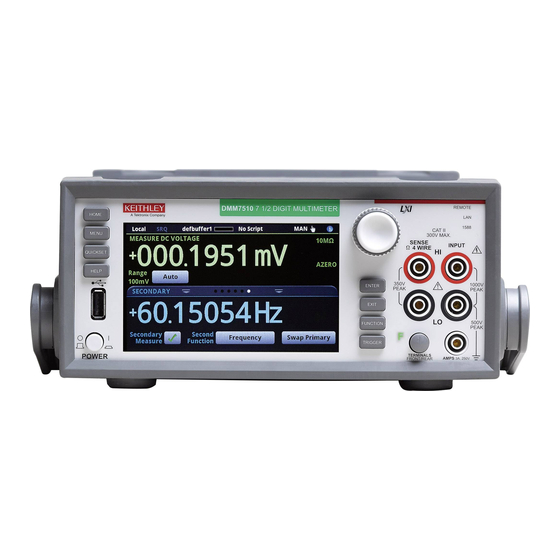
Interactive swipe screens ............2-7 Menu overview ............... 2-13 Front-panel overview The front panel of the Model DMM7510 is shown below. Descriptions of the controls on the front panel follow the figure. Figure 1: Model DMM7510 front panel Turns the instrument on or off. To turn the instrument on, press POWER switch the power switch so that it is in the on position (|). - Page 11 USB port drive. Also stores and retrieves scripts to and from a USB flash drive. The flash drive must be formatted as a FAT drive. The Model DMM7510 has a high-resolution, five-inch color Touchscreen touchscreen display. The touchscreen accesses swipe screens and menu options.
- Page 12 1588 LED indicator compliant device. 1588 functionality is not supported at this time. This functionality will be made available with a firmware update. See the Model DMM7510 Release Notes on the Keithley Instruments website (http://www.keithley.com) for details. Use the SENSE HI and SENSE LO terminals and the INPUT...
-
Page 13: Instrument Power
Follow the steps below to connect the Model DMM7510 to line power and turn on the instrument. The Model DMM7510 operates from a line voltage of 100 V to 240 V at a frequency of 50 Hz or 60 Hz. It automatically senses line voltage and frequency. -
Page 14: Touchscreen Display
• Turn the navigation control to highlight the item, and then press the navigation control to select it The following topics describe the Model DMM7510 touchscreen in more detail. Scroll bars Some of the interactive screens have additional options that are only visible when you scroll down the screen. -
Page 15: Enter Information
Section 2: Using the front-panel interface Model DMM7510 7½ Digit Multimeter User's Manual Enter information Some of the menu options open a keypad or keyboard that you can use to enter information. For example, if you are setting the GPIB address from the front panel, you see the keypad shown in the following figure. -
Page 16: Adjust The Backlight Brightness And Dimmer
Adjust the backlight brightness and dimmer You can adjust the brightness of the Model DMM7510 touchscreen display and buttons from the front panel or over a remote interface. You can also set the backlight to dim after a specified time has passed with no front-panel activity (available from the front-panel display only). -
Page 17: Swipe Screen Heading Bar
Section 2: Using the front-panel interface Model DMM7510 7½ Digit Multimeter User's Manual Swipe screen heading bar The heading bar of the swipe screen contains the following options. Figure 4: Model DMM7510 swipe screens, maximized and minimized Screen element Description Minimize indicator You can swipe down to minimize the swipe screens. -
Page 18: Functions Swipe Screen
Model DMM7510 7½ Digit Multimeter User's Manual Section 2: Using the front-panel interface FUNCTIONS swipe screen The FUNCTIONS swipe screen highlights the selected measure function and allows you to select a different function. Figure 5: FUNCTIONS swipe screen SETTINGS swipe screen The SETTINGS swipe screen gives you front-panel access to some instrument settings for the selected measure function. -
Page 19: Statistics Swipe Screen
Section 2: Using the front-panel interface Model DMM7510 7½ Digit Multimeter User's Manual STATISTICS swipe screen The STATISTICS swipe screen contains information about the readings in the active reading buffer. When the reading buffer is configured to fill continuously and overwrite older data with new data, the buffer statistics include the data that was overwritten. -
Page 20: Secondary Swipe Screen
To start displaying secondary measurements, select the Second Function and select Secondary Measure. Secondary measurements are only available in Continuous Measurement Mode and Manual Trigger Mode. Refer to "Display results of two measure functions" in the Model DMM7510 Reference Manual. -
Page 21: User Swipe Screen
You can program custom text that appears on the USER swipe screen. For example, you can program the Model DMM7510 to show that a test is in process. Refer to "Customizing a message for the USER swipe screen" in the Model DMM7510 Reference Manual. -
Page 22: Menu Overview
Model DMM7510 7½ Digit Multimeter User's Manual Section 2: Using the front-panel interface Menu overview To access the main menu, press the MENU key on the Model DMM7510 front panel. The figure below shows the organization of the main menu. Figure 11: Model DMM7510 main menu The main menu includes submenus that are labeled in green across the top of the display. -
Page 23: Views Menu
Section 2: Using the front-panel interface Model DMM7510 7½ Digit Multimeter User's Manual Views menu The Views menus allow you to select, configure, and view data that was gathered from measure operations. The Graph menu opens a screen that displays a graph of the measurements in selected reading buffers as traces. -
Page 24: Scripts Menu
System menu The menus under System in the main menu allow you to configure general instrument settings from the Model DMM7510 front panel. Among these settings are the event log, communications, backlight, time, and password settings. The following topics describe the settings that are available on these interactive screens. - Page 25 Section 2: Using the front-panel interface Model DMM7510 7½ Digit Multimeter User's Manual The Calibration menu allows you to start or manage auto calibration. Auto calibration removes measurement errors that are caused by the effects of temperature and time on components. You can also review factory adjustment and verification dates.
-
Page 26: Using A Remote Interface
You can choose from one of several communication interfaces to send commands to and receive responses from the Model DMM7510. You can control the Model DMM7510 from only one communications interface at a time. The first interface on which it receives a message takes control of the instrument. If another interface sends a message, that interface can take control of the instrument. -
Page 27: Supported Remote Interfaces
Figure 12: Model DMM7510 remote interface connections GPIB communications The Model DMM7510 GPIB interface is IEEE Std 488.1 compliant and supports IEEE Std 488.2 common commands and status model topology. You can have up to 15 devices connected to a GPIB interface, including the controller. The maximum cable length is the lesser of either: •... -
Page 28: Install The Gpib Driver Software
Install the GPIB driver software Check the documentation for your GPIB controller for information about where to acquire drivers. Keithley Instruments also recommends that you check the website of the GPIB controller for the latest version of drivers or software. -
Page 29: Set The Gpib Address
Section 3: Using a remote interface Model DMM7510 7½ Digit Multimeter User's Manual Figure 14: Instrument GPIB connections Set the GPIB address The default GPIB address is 16. You can set the address to any address from 1 to 30 if it is unique in the system. -
Page 30: Lan Communications
(on page 3-11). The Model DMM7510 is an LXI version 1.4 Core 2011 compliant instrument that supports TCP/IP and complies with IEEE Std 802.3 (ethernet LAN). There is one LAN port (located on the rear panel of the instrument) that supports full connectivity on a 10 Mbps or 100 Mbps network. The Model DMM7510 automatically detects the speed. -
Page 31: Set Up Lan Communications On The Computer
Section 3: Using a remote interface Model DMM7510 7½ Digit Multimeter User's Manual To set up automatic IP address selection using the front panel: 1. Press the MENU key. 2. Under System, select Communication. 3. Select the LAN tab. 4. For TCP/IP Mode, select Auto. -
Page 32: Usb Communications
USB communications To use the rear-panel USB port, you must have the Virtual Instrument Software Architecture (VISA) layer on the host computer. See "How to install the Keithley I/O Layer" in the Model DMM7510 Reference Manual for more information. VISA contains a USB-class driver for the USB Test and Measurement Class (USBTMC) protocol that, ®... -
Page 33: Connect A Computer To The Model Dmm7510 Using Usb
Model DMM7510 7½ Digit Multimeter User's Manual Connect a computer to the Model DMM7510 using USB To connect the Model DMM7510 to a computer using a USB connection, use Keithley Instruments Model USB-B-1, which is shipped with the instrument. Each Model DMM7510 needs its own USB cable to be connected to the computer. - Page 34 Section 3: Using a remote interface To use the Keithley Configuration Panel to determine the VISA resource string: 1. Click Start > All Programs > Keithley Instruments > Keithley Configuration Panel. The Select Operation dialog box is displayed. Figure 15: Select Operation dialog box 2.
- Page 35 9. In the Virtual Instrument Name box, enter a name that you want to use to refer to the instrument. 10. Click Finish. 11. Click Cancel to close the Wizard. 12. Save the configuration. From the Keithley Configuration Panel, select File > Save. 3-10 DMM7510-900-01 Rev. B / May 2015 北京海洋兴业科技股份有限公司(证券代码:839145)...
-
Page 36: Using The Web Interface
If you have the Agilent IO Libraries on your system, you can run Agilent Connection Expert to check your USB instruments. See the Agilent documentation for information. Using the web interface The Model DMM7510 web interface allows you to make settings and control your instrument through a web page. The web page includes: •... -
Page 37: Connect To The Instrument Web Interface
Section 3: Using a remote interface Model DMM7510 7½ Digit Multimeter User's Manual Connect to the instrument web interface When the LAN and instrument establish a connection, you can open a web page for the instrument. To access the web interface: 1. - Page 38 Model DMM7510 7½ Digit Multimeter User's Manual Section 3: Using a remote interface Figure 20: Model DMM7510 web-interface home page The Home page of the instrument provides information about the instrument. It includes: • The instrument model number, manufacturer, serial number, and firmware revision number.
-
Page 39: Identify The Instrument
To clear the event log and update the information on the screen, click the Refresh button. Determining the command set you will use You can change the command set that you use with the Model DMM7510. The remote command sets that are available include: •... - Page 40 Model DMM7510 7½ Digit Multimeter User's Manual Section 3: Using a remote interface To verify which command set is selected from a remote interface: Send the command: *LANG? To change to the SCPI command set from a remote interface: Send the command: *LANG SCPI Reboot the instrument.
-
Page 41: Making Basic Front-Panel Measurements
Model DMM7510 • Two insulated banana cables (you can use the Model 1756 Standard Test Lead Kit that is provided with the Model DMM7510, or equivalent) • One resistor to test; the example uses a resistor with a 9.75 kΩ rating 北京海洋兴业科技股份有限公司(证券代码:839145)... -
Page 42: Device Connections
Model DMM7510 7½ Digit Multimeter User's Manual Device connections Connect the Model DMM7510 to the resistor in a 2-wire (local sense) configuration. In this configuration, the device is connected between the INPUT HI and INPUT LO terminals. To make the connections: 1. -
Page 43: Basic Front-Panel Measurements
Model DMM7510 7½ Digit Multimeter User's Manual Section 4: Making basic front-panel measurements Basic front-panel measurements The following procedures show you how to make a measurement, access settings for the measurement, and view measurement data in a reading buffer. You can make measurements continuously or manually. When you make continuous measurements, the instrument makes measurements as quickly as possible. - Page 44 Section 4: Making basic front-panel measurements Model DMM7510 7½ Digit Multimeter User's Manual Using the front panel to view the contents of a reading buffer: 1. Press the MENU key. Under Views, select Reading Table. Data for the active reading buffer is displayed.
-
Page 45: Measuring Dc Voltage With High Accuracy
High-accuracy DC voltage measurements ....... 5-3 Introduction This example application demonstrates how to use a Model DMM7510 to make a high-accuracy DC voltage measurement. This type of test is often done in metrology labs, where high accuracy is required for calibration and verification. - Page 46 Section 5: Measuring DC voltage with high accuracy Model DMM7510 7½ Digit Multimeter User's Manual Figure 24: Front-panel connections for high-accuracy DC voltage measurements Figure 25: Rear-panel connections for high-accuracy DC voltage measurements To prevent electric shock, test connections must be configured such that the user cannot come in contact with test leads or any device under test (DUT) that is in contact with the conductors.
-
Page 47: High-Accuracy Dc Voltage Measurements
Section 5: Measuring DC voltage with high accuracy High-accuracy DC voltage measurements This application demonstrates how to use the Model DMM7510 to make a high-accuracy DC voltage measurement. You can make the measurement from the front panel or over the remote interface using SCPI code or TSP code. -
Page 48: Using Scpi Commands
This sequence of SCPI commands sets up and runs a single high-accuracy DC voltage measurement when a device under test is connected to the Model DMM7510 and controlled remotely. You may need to make changes so that this code will run in your programming environment. -
Page 49: Using Tsp Commands
To use other programming environments, you may need to make changes to the example TSP code. By default, the Model DMM7510 is configured to use the SCPI command set. You must select the TSP command set before sending TSP commands to the instrument. -
Page 50: Test Results
Section 5: Measuring DC voltage with high accuracy Model DMM7510 7½ Digit Multimeter User's Manual Test results The following table shows the tradeoff between accuracy and speed of measurements based on the integration rate (NPLC), averaging filter, and autozero settings. The first row of data is from the setup documented in this example. -
Page 51: Measuring 4-Wire Resistance With Offset Compensation
Device connections ..............6-2 4-wire resistance measurements with offset compensation ..6-3 Introduction This application example demonstrates how to use the Model DMM7510 to accurately measure a resistance device. To provide the best resistance measurement accuracy, the four-wire (Kelvin) measurement and the offset compensation methods are used for this test. -
Page 52: Device Connections
There is no internal connection between protective earth (safety ground) and the LO terminals of the Model DMM7510. Therefore, hazardous voltages (more than 30 V ) can appear on LO terminals. This can occur when the instrument is operating in any mode. To prevent hazardous voltage from appearing on the LO terminals, connect the LO terminal to protective earth if your application allows it. -
Page 53: 4-Wire Resistance Measurements With Offset Compensation
Figure 27: Rear-panel connections for 4-wire resistance measurements 4-wire resistance measurements with offset compensation This application demonstrates how to use the Model DMM7510 to measure the resistance of a device or component. You can make this measurement from the Model DMM7510 front panel or over the remote interface using SCPI code or TSP code. -
Page 54: Using The Front Panel
This sequence of SCPI commands measures the resistance of a device or component. The device under test is connected to the Model DMM7510 and controlled remotely. You may need to make changes so that this code will run in your programming environment. -
Page 55: Using Tsp Commands
To use other programming environments, you may need to make changes to the example TSP code. By default, the Model DMM7510 is configured to use the SCPI command set. You must select the TSP command set before sending TSP commands to the instrument. -
Page 56: Sampling Temperature At A Set Time Interval
It can be important for product quality during production or storage to know the ambient temperature of the testing environment. You can use the Model DMM7510 to set up a temperature monitoring system that samples temperatures at a fixed time interval for an extended period. -
Page 57: Device Connections
Section 7: Sampling temperature at a set time interval Model DMM7510 7½ Digit Multimeter User's Manual Device connections Use of a four-wire resistance temperature detector (RTD) reduces the effects of lead resistance on accuracy and provides high stability. You can use either the front or rear input terminals for this test. Both front-panel and rear-panel connections are safety banana jacks. -
Page 58: Sample Temperatures At A Specific Time Interval
LO terminal. Sample temperatures at a specific time interval This application demonstrates how to use the Model DMM7510 to measure temperature at fixed time intervals using commands sent over a remote interface. You can make the measurement using SCPI code or TSP code. - Page 59 Section 7: Sampling temperature at a set time interval Model DMM7510 7½ Digit Multimeter User's Manual Using SCPI commands This sequence of SCPI commands makes temperature readings every minute for 24 hours. You may need to make changes so that this code will run in your programming environment. In the table, the SCPI commands have a light gray background.
-
Page 60: Using Tsp
To use other programming environments, you may need to make changes to the example TSP code. By default, the Model DMM7510 is configured to use the SCPI command set. You must select the TSP command set before sending TSP commands to the instrument. -
Page 61: Test Results
--Print the temperature readings and the corresponding timestamps printbuffer(1,defbuffer1.n,defbuffer1) printbuffer(1,defbuffer1.n,defbuffer1.relativetimestamps) Test results The following figures show a sample graph and final test measurement for this application. Figure 30: Model DMM7510 graph of temperature measurements DMM7510-900-01 Rev. B / May 2015 北京海洋兴业科技股份有限公司(证券代码:839145) 电话:010-62176775 网址:www.hyxyyq.com... - Page 62 Model DMM7510 7½ Digit Multimeter User's Manual Section 7: Sampling temperature at a set time interval Figure 31: Model DMM7510 final temperature measurement DMM7510-900-01 Rev. B / May 2015 北京海洋兴业科技股份有限公司(证券代码:839145) 电话:010-62176775 网址:www.hyxyyq.com...
-
Page 63: Grading And Binning Resistors
Section 8 Grading and binning resistors Refer to the "Grading and binning resistors" topic in the Model DMM7510 reference manual. In this section: Introduction ................8-1 Instrument connections ............8-2 Resistor grading and binning test ..........8-2 Introduction This application example demonstrates how to use the Model DMM7510 to perform benchtop binning operations. -
Page 64: Instrument Connections
DMM7510. The signals are sent to the component handler, which bins the devices. The figure below shows the rear-panel connections from the Model DMM7510 to the test fixture and the digital lines to the component handler. In addition, there is GPIB communication between the controller and the component handler. -
Page 65: Trigger Model Template: Gradebinning
Model DMM7510 7½ Digit Multimeter User's Manual Section 8: Grading and binning resistors If a resistor passes the 20 % limit test, the resistance value is checked against Limit 2, which is the 10 % limit value. If the resistor fails this limit inspection, the resistance is outside of the 10 % tolerance band. -
Page 66: Overview Of The Application
Section 8: Grading and binning resistors Model DMM7510 7½ Digit Multimeter User's Manual Overview of the application For this application, you will: • Reset the instrument. • Select the four-wire resistance function. • Enable offset compensation. • Auto zero once. -
Page 67: Using Scpi Commands
Model DMM7510 7½ Digit Multimeter User's Manual Section 8: Grading and binning resistors Using SCPI commands This sequence of SCPI commands grades resistors into bins based on the measured accuracy. You may need to make changes so that this code will run in your programming environment. -
Page 68: Using Tsp Commands
To use other programming environments, you may need to make changes to the example TSP code. By default, the Model DMM7510 is configured to use the SCPI command set. You must select the TSP command set before sending TSP commands to the instrument. - Page 69 Model DMM7510 7½ Digit Multimeter User's Manual Section 8: Grading and binning resistors -- an end-of-test trigger to the component handler digio.line[6].mode = digio.MODE_TRIGGER_OUT -- Output a falling edge trigger trigger.digout[6].logic = trigger.LOGIC_NEGATIVE -- Set width of output trigger pulse to 10 us trigger.digout[6].pulsewidth = 10E-6...
-
Page 70: Integrating With A Model 3706A-S Using Tsp-Link
Integrating with a Model 3706A-S test ........9-4 Introduction This application example demonstrates how to configure the Model DMM7510 and Model 3706A-S System Switch to interact through TSP-Link. The application measures different types of signals on multiple channels in multiple slots of a Model 3706A-S. -
Page 71: Device Connections
TSP-Link functionality is only available when using the instrument front panel or the TSP commands to control the instrument. It is not available if you are using SCPI commands. Refer to the figure below for connections between the Model DMM7510 and the Model 3706A-S. DMM7510-900-01 Rev. B / May 2015 北京海洋兴业科技股份有限公司(证券代码:839145)... - Page 72 There is no internal connection between protective earth (safety ground) and the LO terminals of the Model DMM7510. Therefore, hazardous voltages (more than 30 V ) can appear on LO terminals. This can occur when the instrument is operating in any mode. To prevent hazardous voltage from appearing on the LO terminals, connect the LO terminal to protective earth if your application allows it.
-
Page 73: Integrating With A Model 3706A-S Test
6. Press the EXIT key a couple of times to exit to the main display. The communication from the computer is made directly to the Model DMM7510 in the following TSP code. This makes the Model DMM7510 the master in this TSP-Link network, with the Model 3706A-S as the subordinate. -
Page 74: Using Scpi
To use other programming environments, you may need to make changes to the example TSP code. By default, the Model DMM7510 is configured to use the SCPI command set. You must select the TSP command set before sending TSP commands to the instrument. - Page 75 = node[2].dmm.OFF node[2].dmm.measure.configlist.store("myScanConfigList") --index4 --Handshaking between the Model DMM7510 and Model 3706A-S --Configure Model DMM7510 TSP-Link line 1 to input trigger from Model 3706A-S node[2].tsplink.line[1].mode = node[2].tsplink.MODE_TRIGGER_OPEN_DRAIN --input from Model 3706A-S --Configure Model DMM7510 TSP-Link line 2 to output trigger to Model 3706A-S node[2].tsplink.line[2].mode = node[2].tsplink.MODE_TRIGGER_OPEN_DRAIN...
- Page 76 = node[1].scan.ON node[1].scan.mode = node[1].scan.MODE_FIXED_ABR --Create a Model DMM7510 trigger model that will wait for an input trigger from Model 3760A-S indicating a channel is closed before making a measurement. output trigger will be sent to the Model 3706A-S from the Model DMM7510 upon completing the measurement before closing another the channel node[2].defbuffer1.capacity = node[1].scan.stepcount...
- Page 77 17) --Initiate trigger models on both Model 3706A-S and Model DMM7510 and wait until finished node[2].trigger.model.initiate() -- To guarantee that the Model DMM7510 trigger model is at WAIT block (block 2) delay(2) node[1].scan.background() waitcomplete() --Open all channels on slot 1 and 4 node[1].channel.open("slot1, slot4")
-
Page 78: Capturing And Analyzing Waveforms
• Four insulated banana cables, such as the Keithley Instruments Model 1756 Standard Test Lead Kit (one set with two cables is provided with the Model DMM7510; you will need another set) • Resistors for a varying load application; the application shown here uses resistor from 3 Ω to 8 Ω... -
Page 79: Device Connections
Section 10: Capturing and analyzing waveforms Model DMM7510 7½ Digit Multimeter User's Manual Device connections This application example consists of four tests with different connections. An overview of the connections is shown in the figure below. You can use either the front or rear panel connections for these tests. Check the front panel TERMINALS switch to verify that the instrument is set to read the correct set of terminals (F is lit for front terminals;... -
Page 80: Testing A Buck Converter
The following test will use the Texas Instruments LM25088 evaluation board (EVM) to demonstrate the digitizing capabilities of the Model DMM7510. Modifications were made to the LM25088 evaluation board to realize a 50 kHz switching frequency. An input voltage of 12 V is used on all subsequent tests. -
Page 81: Ripple Noise On The Output Voltage
Section 10: Capturing and analyzing waveforms Model DMM7510 7½ Digit Multimeter User's Manual Ripple noise on the output voltage This test measures the ripple voltage captured on the output terminal of the buck converter evaluation board. For this test, you will: •... - Page 82 Model DMM7510 7½ Digit Multimeter User's Manual Section 10: Capturing and analyzing waveforms Run the test using the front panel To run the test using the front panel: 1. Press the POWER button on the front panel to turn on the instrument.
- Page 83 To use other programming environments, you may need to make changes to the example TSP code. By default, the Model DMM7510 is configured to use the SCPI command set. You must select the TSP command set before sending TSP commands to the instrument.
-
Page 84: Duty Cycle From Switch Node Voltage
Model DMM7510 7½ Digit Multimeter User's Manual Section 10: Capturing and analyzing waveforms Send the following commands: --Reset the instrument to default settings. reset() --Create a local variable to store the number of samples numofsamples = 100 --Set the measure function to digitize voltage to capture the ripple waveform dmm.digitize.func = dmm.FUNC_DIGITIZE_VOLTAGE... - Page 85 Section 10: Capturing and analyzing waveforms Model DMM7510 7½ Digit Multimeter User's Manual For this test, you will: • Connect the 3 Ω load resistor to the output terminals of the buck converter • Connect one test lead to the switch node voltage of the buck converter •...
- Page 86 Model DMM7510 7½ Digit Multimeter User's Manual Section 10: Capturing and analyzing waveforms Run the test using the front panel Running the duty-cycle test from the front panel: 1. Press the POWER button on the front panel to turn on the instrument.
- Page 87 Section 10: Capturing and analyzing waveforms Model DMM7510 7½ Digit Multimeter User's Manual Figure 39: Duty cycle 3 • ∆high = 8.029 µs • ∆period = 19.16 µs • Duty cycle = 8.029 µs /19.16 µs = 40 % •...
-
Page 88: Inductor Current Linearity With Varying Load
— you cannot mix connections. Both front-panel and rear-panel connections are safety banana jacks. You can make these connections with two insulated banana cables (for example, the leads included with the Keithley Instruments Model 1756 Standard Test Lead Kit). - Page 89 Section 10: Capturing and analyzing waveforms Model DMM7510 7½ Digit Multimeter User's Manual Run the test using the front panel Running the inductor current linearity test from the front panel: 1. Press the POWER button on the front panel to turn on the instrument.
- Page 90 Model DMM7510 7½ Digit Multimeter User's Manual Section 10: Capturing and analyzing waveforms Figure 43: Inductor current linearity results at 8 ohms Using SCPI commands You may need to make changes so that this code will run in your programming environment.
- Page 91 To use other programming environments, you may need to make changes to the example TSP code. By default, the Model DMM7510 is configured to use the SCPI command set. You must select the TSP command set before sending TSP commands to the instrument.
-
Page 92: Power-Up Behavior
Section 10: Capturing and analyzing waveforms Power-up behavior You can use the Model DMM7510 to capture the start-up behavior of the buck converter. The start-up inspection can ensure that the device turns on in a reasonable amount of time without any unexpected glitches or pulses. - Page 93 — you cannot mix connections. Both front-panel and rear-panel connections are safety banana jacks. You can make these connections with two insulated banana cables (for example, the leads included with the Keithley Instruments Model 1756 Standard Test Lead Kit).
- Page 94 Model DMM7510 7½ Digit Multimeter User's Manual Section 10: Capturing and analyzing waveforms Run the test using the front panel Set up the digitize function: 1. Press the POWER button on the front panel to turn on the instrument. 2. On the FUNCTIONS swipe screen, select Digi V to select the digitize voltage function.
- Page 95 To use other programming environments, you may need to make changes to the example TSP code. By default, the Model DMM7510 is configured to use the SCPI command set. You must select the TSP command set before sending TSP commands to the instrument.
- Page 96 Model DMM7510 7½ Digit Multimeter User's Manual Section 10: Capturing and analyzing waveforms Send the following commands: --Reset the instrument to default settings reset() --Create a local variable to store the number of samples numofsamples = 10000 --Set the measure function to digitize voltage to capture the power-up behavior dmm.digitize.func = dmm.FUNC_DIGITIZE_VOLTAGE...
Need help?
Do you have a question about the DMM7510 and is the answer not in the manual?
Questions and answers