Keithley DMM6500 User Manual
6 1/2-digit bench/system multimeter
Hide thumbs
Also See for DMM6500:
- Calibration manual (99 pages) ,
- Quick start manual (23 pages) ,
- Manual (123 pages)

Related Manuals for Keithley DMM6500


Summary of Contents for Keithley DMM6500
- Page 1 Model DMM6500 6½-Digit Bench/System Multimeter User’s Manual DMM6500-900-01 Rev. A / April 2018 *PDMM6500-900-01A* DMM6500-900-01A...
- Page 2 Cleveland, Ohio, U.S.A. All rights reserved. Any unauthorized reproduction, photocopy, or use of the information herein, in whole or in part, without the prior written approval of Keithley Instruments, LLC, is strictly prohibited. These are the original instructions in English. ®...
- Page 4 Keithley products are designed for use with electrical signals that are measurement, control, and data I/O connections, with low transient overvoltages, and must not be directly connected to mains voltage or to voltage sources with high transient overvoltages.
- Page 5 (note that selected parts should be purchased only through Keithley to maintain accuracy and functionality of the product). If you are unsure about the applicability of a replacement component, call a Keithley office for information.
-
Page 7: Table Of Contents
Front-panel overview ......................2-1 TRIGGER key ........................... 2-2 Instrument power ......................... 2-3 Connect the power cord ......................2-4 Turn the DMM6500 on or off ..................... 2-4 Touchscreen display ......................2-5 Select items on the touchscreen ....................2-5 Scroll bars ..........................2-5 Enter information ........................ - Page 8 Table of contents DMM6500 6½ Digit Multimeter User's Manual USB communications ......................3-5 Connect a computer to the DMM6500 using USB ..............3-5 Communicate with the instrument ..................... 3-6 GPIB communications ......................3-9 Install the KTTI-GPIB accessory card ..................3-9 Set the GPIB address ......................
- Page 9 Is there any software to help me get started ..............10-2 How do I upgrade the firmware? ..................10-2 Why can't the DMM6500 read my USB flash drive? ............10-3 How do I change the command set? ................. 10-3 How do I save the present state of the instrument? ............10-4 Why did my settings change? ....................
- Page 10 Table of contents DMM6500 6½ Digit Multimeter User's Manual Next steps ....................... 11-1 Additional DMM6500 information ..................11-1 Index ........................... I-1...
-
Page 11: Introduction
Application examples ............... 1-3 Welcome Thank you for choosing a Keithley Instruments product. The DMM6500 is a 6½ digit bench/system digital multimeter with scanning that expands standard DMM functions with high-speed digitizing and large graphical color touchscreen display. This DMM offers a broad range of measurement capabilities, including 15 measurement functions. -
Page 12: Contact Information
Using a remote interface: (on page 3-1) Describes the basics of remote communications and using the instrument web interface. • Application examples (see below): Provides detailed examples of how to use the DMM6500 in some typical situations. • Troubleshooting FAQs: (on page 10-1) Provides answers to frequently asked questions to help you troubleshoot common problems encountered with the DMM6500. -
Page 13: Application Examples
DMM6500 and a two-terminal device under test. • Measuring DC voltage with high accuracy: (on page 5-1) Shows how to use a DMM6500 to make a high-accuracy DC voltage measurement. • Measuring 4-wire resistance with offset compensation: (on page 6-1) Shows how to use the DMM6500 to accurately measure a resistance device. -
Page 15: Front-Panel Overview
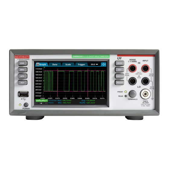
Interactive swipe screens ............2-7 Menu overview ............... 2-14 Front-panel overview The front panel of the DMM6500 is shown below. Descriptions of the controls on the front panel follow the figure. Figure 1: DMM6500 front panel Turns the instrument on or off. To turn the instrument on, press POWER switch and hold the power switch. -
Page 16: Trigger Key
You can also store and retrieve scripts to and from a USB flash drive. The flash drive must be formatted as a FAT or FAT32 drive. The DMM6500 has a high-resolution, five-inch color touchscreen Touchscreen display. The touchscreen accesses swipe screens and menu options. -
Page 17: Instrument Power
Follow the steps below to connect the DMM6500 to line power and turn on the instrument. The DMM6500 operates from a line voltage of 100 V to 240 V at a frequency of 50 Hz, 60 Hz, or 400 Hz. -
Page 18: Connect The Power Cord
Section 2: Front-panel overview DMM6500 6½ Digit Multimeter User's Manual The power cord supplied with the DMM6500 contains a separate protective earth (safety ground) wire for use with grounded outlets. When proper connections are made, the instrument chassis is connected to power-line ground through the ground wire in the power cord. -
Page 19: Touchscreen Display
To select an item on the displayed screen: • Press the corresponding icon on the screen. The following topics describe the DMM6500 touchscreen in more detail. Scroll bars Some of the interactive screens have additional options that are only visible when you scroll down the screen. -
Page 20: Enter Information
Adjust the backlight brightness and dimmer You can adjust the brightness of the DMM6500 touchscreen display and buttons from the front panel or over a remote interface. You can also set the backlight to dim after a specified time has passed with no front-panel activity (available from the front-panel display only). -
Page 21: Review Event Messages
Figure 4: Example front-panel event message Interactive swipe screens The DMM6500 touchscreen display has multiple screens that you can access by swiping left or right on the lower half of the display. The options available in the swipe screens are described in the following topics. - Page 22 Section 2: Front-panel overview DMM6500 6½ Digit Multimeter User's Manual Screen element Description Minimize indicator You can swipe down to minimize the swipe screens. Swipe screen indicator Each circle represents one swipe screen. As you swipe right or left, a different circle changes color, indicating where you are in the screen sequence.
-
Page 23: Functions Swipe Screen
DMM6500 6½ Digit Multimeter User's Manual Section 2: Front-panel overview FUNCTIONS swipe screen The FUNCTIONS swipe screen highlights the selected measure function and allows you to select a different function. Figure 6: FUNCTIONS swipe screen SETTINGS swipe screen The SETTINGS swipe screen gives you front-panel access to some instrument settings for the selected measure function. -
Page 24: Statistics Swipe Screen
Section 2: Front-panel overview DMM6500 6½ Digit Multimeter User's Manual STATISTICS swipe screen The STATISTICS swipe screen contains information about the readings in the active reading buffer. When the reading buffer is configured to fill continuously and overwrite old data with new data, the buffer statistics include the data that was overwritten. -
Page 25: Secondary Swipe Screen
Measure. Secondary measurements are only available in Continuous Measurement Mode and Manual Trigger Mode. This feature is only available from the front panel of the instrument. Refer to "Display results of two measure functions" in the Model DMM6500 Reference Manual. Figure 9: SECONDARY swipe screen Depending on the selected functions, a relay may click when the instrument switches between the measurement types. -
Page 26: User Swipe Screen
If you program custom text, it is displayed on the USER swipe screen. For example, you can program the DMM6500 to show that a test is in process. This swipe screen is only displayed if custom text has been displayed. Refer to "Customizing a message for the USER swipe screen" in the Model DMM6500 Reference Manual. -
Page 27: Scan Swipe Screen
You can also open the full-function Graph screen by pressing the MENU key and selecting Graph under Views. For more information about graphing measurements, see "Graphing" in the Model DMM6500 Reference Manual. SCAN swipe screen The SCAN swipe screen gives you front-panel access to build a scan, edit a scan, start a scan, step through a scan, and display scan results. -
Page 28: Menu Overview
Incrementally steps through a scan, channel by channel. Step Scan Menu overview To access the main menu, press the MENU key on the DMM6500 front panel. The figure below shows the organization of the main menu. Figure 14: DMM6500 main menu The main menu includes submenus that are labeled in green across the top of the display. -
Page 29: Channel Menu
DMM6500 6½ Digit Multimeter User's Manual Section 2: Front-panel overview Channel menu The Channel menus allow you to set up and control channels and scans from the front panel. The Channel Settings menu allows you to select and configure channels. -
Page 30: Views Menu
Section 2: Front-panel overview DMM6500 6½ Digit Multimeter User's Manual Views menu The Views menus allow you to select, configure, and view data that was gathered from measure operations. The Graph menu opens a screen that displays a graph of the measurements in selected reading buffers as traces. -
Page 31: Scripts Menu
System menu The menus under System in the main menu allow you to configure general instrument settings from the DMM6500 front panel. Among these settings are the event log, communications, backlight, time, and password settings, calibration, and info/manage. The Event Log menu allows you to view and clear event log entries. You can also adjust which events are displayed or logged. - Page 32 Section 2: Front-panel overview DMM6500 6½ Digit Multimeter User's Manual The Info/Manage menu gives you access to version and serial number information and settings for instrument firmware and reset functions. 2-18 DMM6500-900-01Rev. A / April 2018...
-
Page 33: Using A Remote Interface
In addition, you do not need to reboot if you change the type of interface that is connected. You can only use one communications interface to control the DMM6500 at a time. The USB connection takes precedence over LAN connections. For other communications interfaces, the first interface on which the instrument receives a message takes control of the instrument. -
Page 34: Supported Remote Interfaces
(on page 3-15). The DMM6500 is a version 1.5 LXI Device Specification 2016 compliant instrument that supports TCP/IP and complies with IEEE Std 802.3 (ethernet LAN). There is one LAN port (located on the rear panel of the instrument) that supports full connectivity on a 10 Mbps or 100 Mbps network. The DMM6500 automatically detects the speed. -
Page 35: Set Up Lan Communications On The Instrument
DMM6500 6½ Digit Multimeter User's Manual Section 3: Using a remote interface Contact your network administrator to confirm your specific network requirements before setting up a LAN connection. If you have problems setting up the LAN, refer to LAN troubleshooting suggestions (on page 3-16). -
Page 36: Set Up Lan Communications On The Computer
Contact your system administrator for more information. Wait for the LAN status indicator to turn green Make sure that your DMM6500 is connected to the network by confirming that your instrument was assigned an IP address. To verify the LAN connection: 1. -
Page 37: Usb Communications
DMM6500 6½ Digit Multimeter User's Manual Section 3: Using a remote interface Use the LXI Discovery Tool To find the IP address of the DMM6500, use the LXI Discovery Tool, a utility that is available from the Resources tab of the LXI Consortium website (http://www.lxistandard.org/). -
Page 38: Communicate With The Instrument
INSTR: Use the USBTMC protocol To determine these parameters, you can run the Keithley Configuration Panel, which automatically detects all instruments connected to the computer. If you installed the Keithley I/O Layer, you can access the Keithley Configuration Panel through the ® ®... - Page 39 DMM6500 6½ Digit Multimeter User's Manual Section 3: Using a remote interface 3. Select Next. The Select Communication Bus dialog box is displayed. Figure 17: Select Communication Bus dialog box 4. Select USB. 5. Click Next. The Select Instrument Driver dialog box is displayed.
- Page 40 9. In the Virtual Instrument Name box, enter a name that you want to use to refer to the instrument. 10. Select Finish. 11. Select Cancel to close the Wizard. 12. Save the configuration. From the Keithley Configuration Panel, select File > Save. Verify the instrument through the Keithley Communicator: 1. Click Start > Keithley Instruments > Keithley Communicator.
-
Page 41: Gpib Communications
Control utility. See the National Instruments documentation for information. GPIB communications The DMM6500 GPIB interface is IEEE Std 488.1 compliant and supports IEEE Std 488.2 common commands and status model topology. You can have up to 15 devices connected to a GPIB interface, including the controller. The maximum cable length is the lesser of either: •... - Page 42 6. Reconnect the power line cable and any other cables to the rear panel. 7. Turn on the instrument. Connect GPIB cables to your instrument To connect a DMM6500 to the GPIB interface, use a cable equipped with standard GPIB connectors, as shown below. Figure 22: GPIB connector To allow many parallel connections to one instrument, stack the connectors.
- Page 43 DMM6500 6½ Digit Multimeter User's Manual Section 3: Using a remote interface Figure 23: DMM6500 Instrument GPIB connections Additional information Additional information is available in the KTTI-GPIB Accessory Installation Sheet. DMM6500-900-01Rev. A / April 2018 3-11...
-
Page 44: Set The Gpib Address
Section 3: Using a remote interface DMM6500 6½ Digit Multimeter User's Manual Set the GPIB address Set the GPIB address. The default GPIB address is 16. You can set the address from one to 30 if it is unique in the system. This address cannot conflict with an address that is assigned to another instrument or to the GPIB controller. - Page 45 DMM6500 6½ Digit Multimeter User's Manual Section 3: Using a remote interface To install the communications card: 1. Turn the instrument off and disconnect the power line cord and any other cables connected to the rear panel. 2. Position the instrument so that you are facing the rear panel.
-
Page 46: Tsp-Link
Section 3: Using a remote interface DMM6500 6½ Digit Multimeter User's Manual Additional information Additional information is available in the KTTI-RS232 Accessory Installation Sheet. TSP-Link Install the KTTI-TSP accessory card Unpack and inspect Make sure to handle the KTTI-TSP carefully. Always grasp the card by the side edges. Do not touch board surfaces, components, or areas adjacent to electrical contacts. -
Page 47: Using The Web Interface
Additional information Additional information is available in the KTTI-TSP Accessory Installation Sheet. Using the web interface The DMM6500 web interface allows you to make settings and control your instrument through a web page. The web page includes: • Instrument status. -
Page 48: Lan Troubleshooting Suggestions
Section 3: Using a remote interface DMM6500 6½ Digit Multimeter User's Manual LAN troubleshooting suggestions If you are unable to connect to the web interface of the instrument, check the following items: • The network cable is in the LAN port on the rear panel of the instrument, not one of the ®... -
Page 49: Web Interface Home Page
DMM6500 6½ Digit Multimeter User's Manual Section 3: Using a remote interface Web interface Home page Figure 27: DMM6500 web interface The Home page of the instrument provides information about the instrument. It includes: • The instrument model number, manufacturer, serial number, and firmware revision number. -
Page 50: Determining The Command Set You Will Use
Section 3: Using a remote interface DMM6500 6½ Digit Multimeter User's Manual Determining the command set you will use You can change the command set that you use with the DMM6500. The remote command sets that are available include: •... - Page 51 DMM6500 6½ Digit Multimeter User's Manual Section 3: Using a remote interface To verify which command set is selected from a remote interface: Send the command: *LANG? To change to the SCPI command set from a remote interface: Send the command: *LANG SCPI Reboot the instrument.
-
Page 53: Making Basic Front-Panel Measurements
The applications in this manual use the order of operations to produce the best results. Equipment required for this example Equipment required to perform this test: • One DMM6500 • Two insulated banana cables. • One resistor to test, the example uses a resistor with a 9.75 kΩ rating... -
Page 54: Device Connections
Section 4: Making basic front-panel measurements DMM6500 6½ Digit Multimeter User's Manual Device connections Connect the DMM6500 to the resistor in a 2-wire (local sense) configuration. In this configuration, the device is connected between the INPUT HI and INPUT LO terminals. To make the connections: 1. -
Page 55: Basic Front-Panel Measurements
DMM6500 6½ Digit Multimeter User's Manual Section 4: Making basic front-panel measurements Basic front-panel measurements The following procedures show you how to make a measurement, access settings for the measurement, and view measurement data in a reading buffer. You can make measurements continuously or manually. When you make continuous measurements, the instrument makes measurements as quickly as possible. - Page 56 Section 4: Making basic front-panel measurements DMM6500 6½ Digit Multimeter User's Manual You can view data from the reading buffers through the front panel using the Reading Table. The Reading Table displays the following information: • Index: The sequential number of the reading.
- Page 57 DMM6500 6½ Digit Multimeter User's Manual Section 4: Making basic front-panel measurements When you are using the FRONT terminals to make measurements, the Channel column of the reading table displays "Front." If you are using the REAR terminals, the Channel column displays "Rear."...
-
Page 59: Introduction
Measuring DCV with high accuracy ......... 5-3 Introduction This example application demonstrates how to use a DMM6500 to make high-accuracy DC voltage measurements. This type of test is often done in metrology laboratories where high accuracy is required for calibration and verification. -
Page 60: Measuring Dc Voltage With High Accuracy
DMM6500 6½ Digit Multimeter User's Manual Device connections This example uses the DMM6500 to measure DC voltage using either the front or rear input terminals. Both the front and rear-panel input terminals are safety banana jacks. You must use either the front or the rear terminals. You cannot mix the front and rear connections. -
Page 61: Measuring Dcv With High Accuracy
Measuring DCV with high accuracy This application demonstrates how to use the DMM6500 to make high-accuracy DC voltage measurements. You can make the measurements from the front-panel interface or over the remote interface using SCPI code or TSP code. -
Page 62: Using The Front Panel
Section 5: Measuring DC voltage with high accuracy DMM6500 6½ Digit Multimeter User's Manual Using the front panel To run this example from the front panel: 1. Press the POWER switch on the front panel to turn on the instrument. -
Page 63: Using Scpi Commands
The following TSP code is designed to be run from Keithley Instruments Test Script Builder (TSB). TSB is a software tool that is available from tek.com/keithley. You can install and use TSB to write code and develop scripts for TSP-enabled instruments. Information about how to use TSB is in the online help for TSB and in the “Introduction to TSP operation”... - Page 64 Section 5: Measuring DC voltage with high accuracy DMM6500 6½ Digit Multimeter User's Manual Send the following commands for this example application: --Reset the instrument to the default settings. reset() --Set the measure function to DC voltage. dmm.measure.func = dmm.FUNC_DC_VOLTAGE --Set the measurement range to 10 V.
-
Page 65: Test Results
DMM6500 6½ Digit Multimeter User's Manual Section 5: Measuring DC voltage with high accuracy Test results The following table shows the tradeoff between accuracy and measurement speed based on the integration rate (NPLC), averaging filter, and autozero settings. The first row of data is measured using the setup documented in this example. -
Page 67: Measuring 4-Wire Resistance With Offset Compensation
Measuring 4-wire resistance with offset compensation .... 6-3 Introduction This application example demonstrates how to use the DMM6500 to accurately measure resistance. Typical resistance measurements made using the 2-wire method source current through the test leads and the device under test (DUT). The voltage is measured and the resistance is calculated. -
Page 68: Device Connections
DMM6500 6½ Digit Multimeter User's Manual Device connections This example application uses the DMM6500 to perform a 4-wire resistance-device measurement using offset compensation. Both the front and rear-panel connections are safety banana jacks. You can use either the front or the rear input terminals. -
Page 69: Measuring 4-Wire Resistance With Offset Compensation
Measuring 4-wire resistance with offset compensation This application demonstrates how to use the DMM6500 to measure the resistance of a device or component. You can make this measurement from the front panel or over the remote interface using SCPI or TSP code. -
Page 70: Using The Front Panel
Section 6: Measuring 4-wire resistance with offset compensation DMM6500 6½ Digit Multimeter User's Manual Using the front panel Auto Zero is automatically set to On, and NPLC is automatically set to 1. To set up the application from the front panel: 1. -
Page 71: Using Tsp Commands
The following TSP code is designed to be run from Keithley Instruments Test Script Builder (TSB). TSB is a software tool that is available from tek.com/keithley. You can install and use TSB to write code and develop scripts for TSP-enabled instruments. Information about how to use TSB is in the online help for TSB and in the “Introduction to TSP operation”... -
Page 72: Test Results
Section 6: Measuring 4-wire resistance with offset compensation DMM6500 6½ Digit Multimeter User's Manual Test results The results of a low-resistance measurement test using a 20 Ω resistor are shown in the table below. For example, if the resistor specification has a tolerance of ±0.1% and a temperature coefficient of ±15 ppm/°C, a compliant resistor measures between 19.97 Ω... -
Page 73: Scanning Temperature At A Set Time Interval
During production or storage, the temperature of the testing environment can be important. You can use the DMM6500 to monitor temperature at a fixed time interval for an extended period. This application requires a Keithley Instruments 2001-TCSCAN card. The 2001-TCSCAN provides connections for up to nine channels of thermocouple temperature measurements. -
Page 74: Device Connections
Type K thermocouple. The card is then inserted into the rear of the DMM6500 as shown in the next figure. The instrument must be switched to use the rear terminals. - Page 75 DMM6500 6½ Digit Multimeter User's Manual Section 7: Scanning temperature at a set time interval 3. Install the 2001-TCSCAN card into the accessory card slot of the DMM6500. For information on installing the 2001-TCSCAN card, refer to the Model DMM6500 Reference Manual.
-
Page 76: Sample Temperatures At A Specific Time Interval
Sample temperatures at a specific time interval This example application uses the DMM6500 to scan a set of channels, measuring temperature at a fixed interval. You can control the instrument from the front panel or over the remote interface using SCPI code or TSP code. -
Page 77: Using Scpi Commands
DMM6500 6½ Digit Multimeter User's Manual Section 7: Scanning temperature at a set time interval Using SCPI commands This sequence of SCPI commands executes a thermocouple-based temperature scan every minute for 24 hours. You may need to make changes so that this code will run in your programming environment. In the table, the SCPI commands have a light gray background. -
Page 78: Using Tsp
The following TSP code is designed to be run from Keithley Instruments Test Script Builder (TSB). TSB is a software tool that is available from tek.com/keithley. You can install and use TSB to write code and develop scripts for TSP-enabled instruments. Information about how to use TSB is in the online help for TSB and in the “Introduction to TSP operation”... -
Page 79: Test Results
-- Get the data. printbuffer(1, defbuffer1.n, defbuffer1) Test results The following figures show a sample graph and final test measurement for this application. Figure 39: DMM6500 graph of temperature measurements Figure 40: DMM6500 final temperature measurement DMM6500-900-01Rev. A / April 2018... - Page 80 Section 7: Scanning temperature at a set time interval DMM6500 6½ Digit Multimeter User's Manual DMM6500-900-01Rev. A / April 2018...
- Page 81 It uses the trigger model and digital I/O to control external component-handling devices. The DMM6500 can do simple pass-or-fail testing as well as grading and sorting. Grading resistors is a common application that is done by monitoring multiple limits until the first failure. Binning resistors is also common but unlike grading, binning involves monitoring limits until the first pass is received.
-
Page 82: Device Connections
(grading results) are sent from the instrument to the component handler, which bins the devices. The figure below shows the rear-panel connections from the DMM6500 to the test fixture and the digital lines to the component handler. The optional GPIB communication card connects the controller and the component handler. -
Page 83: Resistor Grading And Binning Test
Resistors are placed into bins based on the bit patterns that are assigned to the limits. In this example, the DMM6500 GradeBinning trigger model template is used to simplify the application. This trigger model template grades components into four tolerance levels (for example, 20-%, 10-%, 5-%, and 1-%) as defined by limits 1 to 4. -
Page 84: Trigger Model Template: Grade And Binning Test
Section 8: Grading and binning resistors DMM6500 6½ Digit Multimeter User's Manual Trigger model template: grade and binning test The trigger model template contains the settings for the number of components, digital I/O, and limits. The command parameters for the template are described in the following command and table. -
Page 85: Using Scpi Commands
DMM6500 6½ Digit Multimeter User's Manual Section 8: Grading and binning resistors Using SCPI commands This sequence of SCPI commands grades resistors into bins based on measured accuracy. You may need to make changes so that this code will run in your programming environment. -
Page 86: Using Tsp Commands
The following TSP code is designed to be run from Keithley Instruments Test Script Builder (TSB). TSB is a software tool that is available from tek.com/keithley. You can install and use TSB to write code and develop scripts for TSP-enabled instruments. Information about how to use TSB is in the online help for TSB and in the “Introduction to TSP operation”... - Page 87 DMM6500 6½ Digit Multimeter User's Manual Section 8: Grading and binning resistors -- an end-of-test trigger to the component handler digio.line[6].mode = digio.MODE_TRIGGER_OUT -- Output a falling edge trigger trigger.digout[6].logic = trigger.LOGIC_NEGATIVE -- Set width of output trigger pulse to 10 us trigger.digout[6].pulsewidth = 10e-6...
-
Page 89: Measuring Power Using Digitizing And Tsp-Link
Equipment required ..............9-2 Device connections ..............9-2 Measuring power using digitizing and TSP-Link....... 9-4 Introduction This application example demonstrates how to configure two DMM6500 instruments to use TSP-Link ® to measure the power consumed by a Bluetooth low energy (BLE) device. -
Page 90: Equipment Required
Section 9: Measuring power using digitizing and TSP-Link DMM6500 6½ Digit Multimeter User's Manual Equipment required This application requires the following equipment: • Two DMM6500 instruments • Two KTTI-TSP communication and digital I/O accessory cards • One computer set up for communication with the instrument •... - Page 91 DMM6500 6½ Digit Multimeter User's Manual Section 9: Measuring power using digitizing and TSP-Link 3. Connect the computer to the DMM6500 that is set to node one. 4. Connect the test leads of the instrument measuring voltage in parallel with the battery of the device.
-
Page 92: Measuring Power Using Digitizing And Tsp-Link
6. Select Initialize on each instrument. The communication from the computer is made directly to the first DMM6500 (node 1) in the following TSP code. This code makes the first DMM6500 the master in this TSP-Link network, with the second DMM6500 as the subordinate. -
Page 93: Using Tsp Commands
The following TSP code is designed to be run from Keithley Instruments Test Script Builder (TSB). TSB is a software tool that is available from tek.com/keithley. You can install and use TSB to write code and develop scripts for TSP-enabled instruments. Information about how to use TSB is in the online help for TSB and in the “Introduction to TSP operation”... - Page 94 Section 9: Measuring power using digitizing and TSP-Link DMM6500 6½ Digit Multimeter User's Manual -- Set up reading buffers. node[2].defbuffer1.capacity = 50000 -- Set up trigger model. node[2].trigger.model.setblock(1, node[2].trigger.BLOCK_WAIT, node[2].trigger.EVENT_TSPLINK1) node[2].trigger.model.setblock(2, node[2].trigger.BLOCK_MEASURE_DIGITIZE, defbuffer1, 50000) -- Show graph of measurements on swipe screens.
-
Page 95: Results
.. " W") Results The voltage and current waveforms captured on the DMM6500 show the power consumption resulting from the use of the DUT. You can identify the transmission state of the device by the areas of high current consumption and the visible drop in voltage from the battery. Because these measurements are triggered within 2 µs of each other, the voltage and current data is synchronized... - Page 96 Section 9: Measuring power using digitizing and TSP-Link DMM6500 6½ Digit Multimeter User's Manual Figure 46: Subordinate node measuring current Figure 47: Subordinate node current waveform DMM6500-900-01Rev. A / April 2018...
-
Page 97: Troubleshooting Faqs
What is the ethernet port number? ......... 10-5 About this section This section helps you find answers to the most common questions encountered with the DMM6500. Where can I find updated drivers? For the latest drivers and additional support information, see the Keithley Instruments support website. -
Page 98: Is There Any Software To Help Me Get Started
Yes. Keithley provides Keithley KickStart and Keithley TestScript Builder to help you get started with the DMM6500. Keithley KickStart is a software program that allows you to set up your instrument and run a test without using any programming languages. -
Page 99: Why Can't The Dmm6500 Read My Usb Flash Drive
SCPI command set. In addition, some Series 2000 or Keysight 34401 code will work differently in the DMM6500 than it did in the earlier instrument. For information about the differences between the DMM6500 and the Series 2000, refer to Keithley Instruments document #0771466, DMM6500 in a Model 2000 application. -
Page 100: How Do I Save The Present State Of The Instrument
After they are saved, you can recall the script or copy it to a USB flash drive. From the front panel: 1. Configure the DMM6500 to the settings that you want to save. 2. Press the MENU key. 3. Under Scripts, select Save Setup. The SAVE SETUP window is displayed. -
Page 101: Why Did My Settings Change
Why did my settings change? Many of the commands in the DMM6500 are saved with the measure function that was active when you set them. For example, assume you have the measure function set to current and you set a value for display digits. - Page 103 In this section: Additional DMM6500 information ........... 11-1 Additional DMM6500 information This manual has prepared you to start using your new DMM6500 6½ Digit Multimeter for your application. For more detailed information, refer to the Keithley Instruments DMM6500 Reference Manual.
- Page 105 Identify the instrument • 3-17 Communicate with the instrument • 3-6 Install the KTTI-GPIB accessory card • 3-9 Connect a computer to the DMM6500 using USB • Install the KTTI-RS232 accessory card • 3-12 Install the KTTI-TSP accessory card • 3-14, 9-2 Connect GPIB cables to your instrument •...
- Page 106 What is the ethernet port number? • 10-5 Scanning temperature at a set time interval • 1-3, 7- Where can I find updated drivers? • 10-1 Why can't the DMM6500 read my USB flash drive? • SCPI • 3-18 10-3 Scripts menu •...
- Page 107 All Keithley trademarks and trade names are the property of Keithley Instruments. All other trademarks and trade names are the property of their respective companies. Keithley Instruments Corporate Headquarters • 28775 Aurora Road • Cleveland, Ohio 44139 • 440-248-0400 • Fax: 440-248-6168 • 1-800-935-5595 • www.tek.com/keithley 12/17...
Need help?
Do you have a question about the DMM6500 and is the answer not in the manual?
Questions and answers
How can i connect probs to measure using secondary display & primary display simultaneously