Table of Contents
Advertisement
Quick Links
Test Equipment Depot - 800.517.8431 - 99 Washington Street Melrose, MA 02176 - TestEquipmentDepot.com
Introduction
This document describes the DMM7512 7½ Digit Multimeter instrument and how it differs from the Model
DMM7510 7½ Digit Multimeter instrument.
The DMM7512 is a no-front-panel version of the DMM7510 that has two DMM modules housed in one
enclosure. Except for the power switch, each module operates independently within the enclosure.
What you should have received
In addition to the DMM7512, you should have received the items in the following table.
Part number
012178100
CA-180-16A
1747107XX
CO-26
CS-568-120A
0713411XX
4299-13 Rack Mount kit, consisting of:
▪
4076126XX
▪
10-32X3/8PHTRSH
▪
10-32X5/8PHTRSH
▪
FA-274
Note: XX is the latest revision number.
071357601 / October 2018
Model DMM7512 7½ Digit Sampling Multimeter
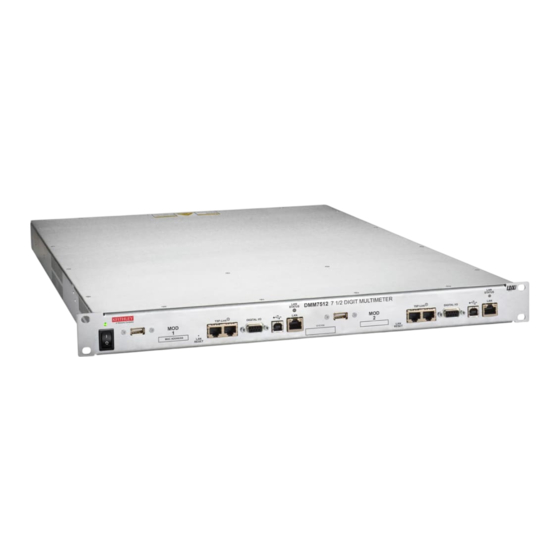
Figure 1: DMM7512 7½ Digit Multimeter
Description
Test lead kit
LAN crossover cable, 16 in.
Shielded crossover cable with RJ-45 connector, 5 ft.
Power line cord
Green and yellow ground cable, 120 in.
Safety precautions
1U rack rail mount
10-32X3/8 Phillips truss head screw
10-32X5/8 Phillips truss head screw
Cage nut
*P071357601*
Instrument Information
Quantity
4
2
1
1
1
1
1
2
4
8
4
1
Advertisement
Table of Contents

Related Manuals for Keithley DMM7512


Summary of Contents for Keithley DMM7512
- Page 1 This document describes the DMM7512 7½ Digit Multimeter instrument and how it differs from the Model DMM7510 7½ Digit Multimeter instrument. The DMM7512 is a no-front-panel version of the DMM7510 that has two DMM modules housed in one enclosure. Except for the power switch, each module operates independently within the enclosure.
-
Page 2: Customer Documentation
The DMM7512 is very similar to the DMM7510. This document describes the differences between the DMM7512 and the DMM7510. Other than the changes described in this document, the products are identical, so you can use the DMM7510 documents as a resource. -
Page 3: Installing The Dmm7512
▪ Installing the DMM7512 The DMM7512 is intended for mounting in a rack only. For detailed instructions, refer to the documentation for the Model 4299-13 Rack Mount Kit (part number 0713574XX). Rack mounting the DMM7512 requires two people. Failure to recognize and observe standard safety precautions could result in personal injury. - Page 4 Model DMM7512 7½ Digit Sampling Multimeter Instrument Information Dimensions The following figures show the mounting screw locations and other dimensions of the instrument. Figure 2: DMM7512 top view Figure 3: Dimensions - front view 071357601 / October 2018...
-
Page 5: Front Panel Overview
Model DMM7512 7½ Digit Sampling Multimeter Instrument Information Figure 4: Dimensions - side view Front-panel overview The front panel of the DMM7512 is shown below. Descriptions of the controls on the front panel follow the figure. Figure 5: DMM7512 front panel Power indicator The power switch turns the instrument on or off. -
Page 6: Rear Panel Overview
LAN). See Setting up remote communications (on page 7). Rear-panel overview The rear panel of the DMM7512 is shown below. The descriptions of the rear-panel components follow the figure. Figure 6: 7512 rear panel INPUT and Use the INPUT HI and INPUT LO terminals for all SENSE terminals measurements except current. -
Page 7: Setting Up Remote Communications
Each module in the instrument has a separate IP configuration. The IP configuration persists through a power cycle. When the DMM7512 is shipped, the IP configurations for each module are set to Manual and are set to the following values: IP address, module 1: 192.168.0.3... - Page 8 2. Wait for the instrument to complete power up. 3. Insert a straightened paper clip into the recessed LAN RESET switch on the DMM7512 front panel, pressing the switch briefly. The LAN status indicator illuminates when the connection is established.
-
Page 9: Accessing The Virtual Front Panel
Model DMM7512 7½ Digit Sampling Multimeter Instrument Information Accessing the virtual front panel If you have a LAN connection, you can access the web interface of each module in the instrument. Each module has its own IP address and is controlled separately. The web interface for each module includes a virtual front panel, which you can use to control the module. -
Page 10: Line Fuse Replacement
Failure to do so could expose the operator to hazardous voltages that could result in personal injury or death. The fuse drawer is above the AC receptacle on the rear panel of the DMM7512, as shown in the following figure. -
Page 11: Verification And Adjustment
The DMM7512 contains two independent DMM modules. Each module requires separate calibration and ▪ adjustment. The DMM7512 does not support AC voltage or AC current functions, and it does not support the 10 A ▪ current range. Therefore, only DC verification and adjustment steps are required. -
Page 12: Safety Precautions
Keithley products are designed for use with electrical signals that are measurement, control, and data I/O connections, with low transient overvoltages, and must not be directly connected to mains voltage or to voltage sources with high transient overvoltages. - Page 13 (note that selected parts should be purchased only through Keithley to maintain accuracy and functionality of the product). If you are unsure about the applicability of a replacement component, call a Keithley office for information.
Need help?
Do you have a question about the DMM7512 and is the answer not in the manual?
Questions and answers