Table of Contents
Troubleshooting

Related Manuals for Keithley DAQ6510


Summary of Contents for Keithley DAQ6510
- Page 1 Model DAQ6510 Data Acquisition and Multimeter System User’s Manual DAQ6510-900-01 Rev. A / April 2018 Test Equipment Depot - 800.517.8431 - 99 Washington Street Melrose, MA 02176 - TestEquipmentDepot.com *PDAQ6510-900-01A* DAQ6510-900-01A...
- Page 2 Cleveland, Ohio, U.S.A. All rights reserved. Any unauthorized reproduction, photocopy, or use of the information herein, in whole or in part, without the prior written approval of Keithley Instruments, LLC, is strictly prohibited. These are the original instructions in English. ®...
- Page 4 Keithley Instruments products are designed for use with electrical signals that are measurement, control, and data I/O connections, with low transient overvoltages, and must not be directly connected to mains voltage or to voltage sources with high transient overvoltages.
- Page 5 (note that selected parts should be purchased only through Keithley Instruments to maintain accuracy and functionality of the product). If you are unsure about the applicability of a replacement component, call a Keithley Instruments office for information.
-
Page 8: Table Of Contents
Front-panel overview ....................2-1 Front-panel overview ......................2-1 Instrument power ......................... 2-3 Connect the power cord ......................2-4 Turn the DAQ6510 on or off ...................... 2-4 Touchscreen display ......................2-5 Select items on the touchscreen ....................2-5 Scroll bars ..........................2-5 Enter information ........................ - Page 9 Table of contents DAQ6510 Data Acquisition / Multimeter System User's Manual Connect a computer to the DAQ6510 using USB ..............3-5 Communicate with the instrument ..................... 3-6 GPIB communications ......................3-9 Install the KTTI-GPIB accessory card ..................3-9 Set the GPIB address ......................3-12 RS-232 ..........................
- Page 10 Is there any software to help me get started ..............11-2 How do I upgrade the firmware? ..................11-2 Why can't the DAQ6510 read my USB flash drive?............11-3 How do I change the command set? ................. 11-3 How do I save the present state of the instrument? ............11-4...
- Page 11 Table of contents DAQ6510 Data Acquisition / Multimeter System User's Manual Why did my settings change? .................... 11-5 What is the ethernet port number? ..................11-5 Next steps ....................... 12-1 Additional DAQ6510 information ..................12-1 Index ........................... I-1...
-
Page 12: Introduction
Application examples ............... 1-3 Welcome Thank you for choosing a Keithley Instruments product. The DAQ6510 is a 6½ digit graphical sampling data-acquisition system that provides high-speed digitizing and a large graphical color touchscreen display. This DAQ offers a broad range of measurement capabilities, including 15 measurement functions. -
Page 13: Extended Warranty
Using a remote interface: (on page 3-1) Describes the basics of remote communications and using the instrument web interface. • Application examples (see below): Provides detailed examples of how to use the DAQ6510 in some typical situations. • Troubleshooting FAQs: (on page 11-1) Provides answers to frequently asked questions to help you troubleshoot common problems encountered with the DAQ6510. -
Page 14: Application Examples
• Pre-scan monitoring: (on page 10-3) Shows how to configure the DAQ6510 to delay its scanning function until the testing environment has reached a specific temperature. DAQ6510-900-01Rev. A / April 2018... -
Page 16: Front-Panel Overview
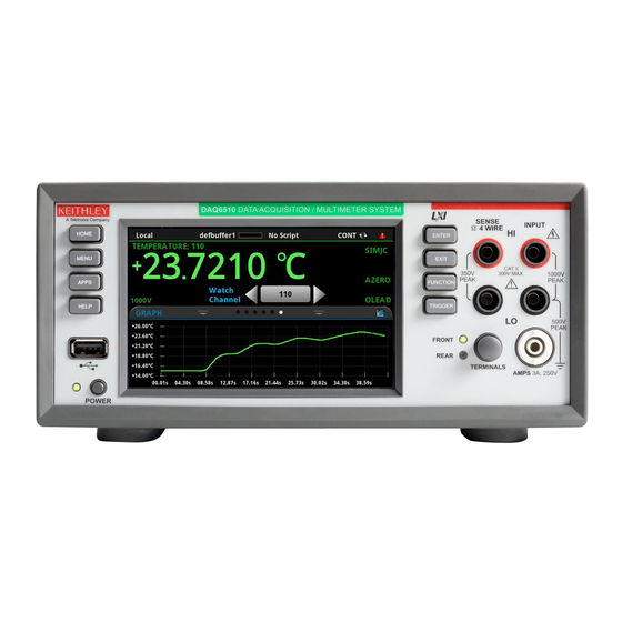
Interactive swipe screens ............2-7 Menu overview ............... 2-16 Front-panel overview The front panel of the DAQ6510 is shown below. Descriptions of the controls on the front panel follow the figure. Figure 1: DMM6500 front panel Turns the instrument on or off. To turn the instrument on, press POWER switch and hold the power switch. - Page 17 Section 2: Front-panel overview DAQ6510 Data Acquisition / Multimeter System User's Manual Opens the main menu. Press the icons on the main menu to open MENU key channel, measure, views, trigger, scripts, and system screens. For details, refer to Menu overview (on page 2-16).
-
Page 18: Instrument Power
Follow the steps below to connect the DAQ6510 to line power and turn on the instrument. The DAQ6510 operates from a line voltage of 100 V to 240 V at a frequency of 50 Hz or 60 Hz. Make sure the operating voltage in your area is compatible. -
Page 19: Connect The Power Cord
Section 2: Front-panel overview DAQ6510 Data Acquisition / Multimeter System User's Manual The power cord supplied with the DAQ6510 contains a separate protective earth (safety ground) wire for use with grounded outlets. When proper connections are made, the instrument chassis is connected to power-line ground through the ground wire in the power cord. -
Page 20: Touchscreen Display
To select an item on the displayed screen: • Press the corresponding icon on the screen. The following topics describe the DAQ6510 touchscreen in more detail. Scroll bars Some of the interactive screens have additional options that are only visible when you scroll down the screen. -
Page 21: Enter Information
Adjust the backlight brightness and dimmer You can adjust the brightness of the DAQ6510 touchscreen display and buttons from the front panel or over a remote interface. You can also set the backlight to dim after a specified time has passed with no front-panel activity (available from the front-panel display only). -
Page 22: Review Event Messages
Figure 4: Example front-panel event message Interactive swipe screens The DAQ6510 touchscreen display has multiple screens that you can access by swiping left or right on the lower half of the display. The options available in the swipe screens are described in the following topics. - Page 23 Section 2: Front-panel overview DAQ6510 Data Acquisition / Multimeter System User's Manual Screen element Description Minimize indicator You can swipe down to minimize the swipe screens. Swipe screen indicator Each circle represents one swipe screen. As you swipe right or left, a different circle changes color, indicating where you are in the screen sequence.
-
Page 24: Functions Swipe Screen
DAQ6510 Data Acquisition / Multimeter System User's Manual Section 2: Front-panel overview FUNCTIONS swipe screen The FUNCTIONS swipe screen highlights the selected measure function and allows you to select a different function. Figure 6: FUNCTIONS swipe screen SETTINGS swipe screen The SETTINGS swipe screen gives you front-panel access to some instrument settings for the selected measure function. -
Page 25: Statistics Swipe Screen
Section 2: Front-panel overview DAQ6510 Data Acquisition / Multimeter System User's Manual STATISTICS swipe screen The STATISTICS swipe screen contains information about the readings in the active reading buffer. When the reading buffer is configured to fill continuously and overwrite old data with new data, the buffer statistics include the data that was overwritten. -
Page 26: Secondary Swipe Screen
Measure. Secondary measurements are only available in Continuous Measurement Mode and Manual Trigger Mode. This feature is only available from the front panel of the instrument. Refer to "Display results of two measure functions" in the Model DAQ6510 Reference Manual. Figure 9: SECONDARY swipe screen Depending on the selected functions, a relay may click when the instrument switches between the measurement types. -
Page 27: User Swipe Screen
If you program custom text, it is displayed on the USER swipe screen. For example, you can program the DAQ6510 to show that a test is in process. Refer to "Customizing a message for the USER swipe screen" in the DAQ6510 Reference Manual. This swipe screen is only displayed if custom text has been displayed. - Page 28 You can also open the full-function Graph screen by pressing the MENU key and selecting Graph under Views. For more information about graphing measurements, see "Graphing" in the Model DAQ6510 Reference Manual. DAQ6510-900-01Rev. A / April 2018...
-
Page 29: Scan Swipe Screen
Section 2: Front-panel overview DAQ6510 Data Acquisition / Multimeter System User's Manual SCAN swipe screen The SCAN swipe screen gives you front-panel access to build a scan, edit a scan, start a scan, step through a scan, and display scan results. You can also save the scan results to a USB flash drive. - Page 30 DAQ6510 Data Acquisition / Multimeter System User's Manual Section 2: Front-panel overview The scan swipe screen has the following control options: Button Description Opens the SCAN screen, where you can set up a new scan. Build Scan Opens the SCAN screen, where you can change the setup of a Edit scan.
-
Page 31: Menu Overview
DAQ6510 Data Acquisition / Multimeter System User's Manual Menu overview To access the main menu, press the MENU key on the DAQ6510 front panel. The figure below shows the organization of the main menu. The options change depending upon which set of terminals are selected, front or rear. -
Page 32: Channel Menu
DAQ6510 Data Acquisition / Multimeter System User's Manual Section 2: Front-panel overview Channel menu The Channel menus allow you to set up and control channels and scans from the front panel. The Channel Settings menu allows you to select and configure channels. -
Page 33: Views Menu
Section 2: Front-panel overview DAQ6510 Data Acquisition / Multimeter System User's Manual Views menu The Views menus allow you to select, configure, and view data that was gathered from measure operations. The Graph menu opens a screen that displays a graph of the measurements in selected reading buffers as traces. -
Page 34: System Menu
System menu The menus under System in the main menu allow you to configure general instrument settings from the DAQ6510 front panel. Among these settings are the event log, communications, backlight, time, and password settings, calibration, and info/manage. The Event Log menu allows you to view and clear event log entries. You can also adjust which events are displayed or logged. -
Page 36: Using A Remote Interface
In addition, you do not need to reboot if you change the type of interface that is connected. You can only use one communications interface to control the DAQ6510 at a time. The USB connection takes precedence over LAN connections. For other communications interfaces, the first interface on which the instrument receives a message takes control of the instrument. -
Page 37: Supported Remote Interfaces
(on page 3-15). The DAQ6510 is an LXI version 1.5 Core 2016 compliant instrument that supports TCP/IP and complies with IEEE Std 802.3 (ethernet LAN). There is one LAN port (located on the rear panel of the instrument) that supports full connectivity on a 10 Mbps or 100 Mbps network. The DAQ6510 automatically detects the speed. -
Page 38: Set Up Lan Communications On The Instrument
DAQ6510 Data Acquisition / Multimeter System User's Manual Section 3: Using a remote interface Contact your network administrator to confirm your specific network requirements before setting up a LAN connection. If you have problems setting up the LAN, refer to LAN troubleshooting suggestions (on page 3-16). -
Page 39: Set Up Lan Communications On The Computer
Contact your system administrator for more information. Wait for the LAN status indicator to turn green Make sure that your DAQ6510 is connected to the network by confirming that your instrument was assigned an IP address. To verify the LAN connection: 1. -
Page 40: Usb Communications
DAQ6510 Data Acquisition / Multimeter System User's Manual Section 3: Using a remote interface Use the LXI Discovery Tool To find the IP address of the DAQ6510, use the LXI Discovery Tool, a utility that is available from the Resources tab of the LXI Consortium website. -
Page 41: Communicate With The Instrument
INSTR: Use the USBTMC protocol To determine these parameters, you can run the Keithley Configuration Panel, which automatically detects all instruments connected to the computer. If you installed the Keithley I/O Layer, you can access the Keithley Configuration Panel through the Microsoft Windows Start menu. - Page 42 DAQ6510 Data Acquisition / Multimeter System User's Manual Section 3: Using a remote interface 3. Select Next. The Select Communication Bus dialog box is displayed. Figure 18: Select Communication Bus dialog box 4. Select USB. 5. Click Next. The Select Instrument Driver dialog box is displayed.
- Page 43 9. In the Virtual Instrument Name box, enter a name that you want to use to refer to the instrument. 10. Select Finish. 11. Select Cancel to close the Wizard. 12. Save the configuration. From the Keithley Configuration Panel, select File > Save. Verify the instrument through the Keithley Communicator: 1. Click Start > Keithley Instruments > Keithley Communicator.
-
Page 44: Gpib Communications
Control utility. See the National Instruments documentation for information. GPIB communications The DAQ6510 GPIB interface is IEEE Std 488.1 compliant and supports IEEE Std 488.2 common commands and status model topology. You can have up to 15 devices connected to a GPIB interface, including the controller. The maximum cable length is the lesser of either: •... - Page 45 6. Reconnect the power line cable and any other cables to the rear panel. 7. Turn on the instrument. Connect GPIB cables to your instrument To connect a DAQ6510 to the GPIB interface, use a cable equipped with standard GPIB connectors, as shown below. Figure 23: GPIB connector To allow many parallel connections to one instrument, stack the connectors.
- Page 46 DAQ6510 Data Acquisition / Multimeter System User's Manual Section 3: Using a remote interface Figure 24: DAQ6510 Instrument GPIB connections Additional information Additional information is available in the KTTI-GPIB Accessory Installation Sheet. DAQ6510-900-01Rev. A / April 2018 3-11...
-
Page 47: Set The Gpib Address
Section 3: Using a remote interface DAQ6510 Data Acquisition / Multimeter System User's Manual Set the GPIB address Set the GPIB address. The default GPIB address is 16. You can set the address from one to 30 if it is unique in the system. - Page 48 DAQ6510 Data Acquisition / Multimeter System User's Manual Section 3: Using a remote interface To install the communications card: 1. Turn the instrument off and disconnect the power line cord and any other cables connected to the rear panel. 2. Position the instrument so that you are facing the rear panel.
-
Page 49: Tsp-Link
Section 3: Using a remote interface DAQ6510 Data Acquisition / Multimeter System User's Manual Additional information Additional information is available in the KTTI-RS232 Accessory Installation Sheet. TSP-Link Install the KTTI-TSP accessory card Unpack and inspect Make sure to handle the KTTI-TSP carefully. Always grasp the card by the side edges. Do not touch board surfaces, components, or areas adjacent to electrical contacts. -
Page 50: Using The Web Interface
Additional information Additional information is available in the KTTI-TSP Accessory Installation Sheet. Using the web interface The DAQ6510 web interface allows you to make settings and control your instrument through a web page. The web page includes: • Instrument status. -
Page 51: Lan Troubleshooting Suggestions
Section 3: Using a remote interface DAQ6510 Data Acquisition / Multimeter System User's Manual LAN troubleshooting suggestions If you are unable to connect to the web interface of the instrument, check the following items: • The network cable is in the LAN port on the rear panel of the instrument, not one of the TSP-Link ports. -
Page 52: Web Interface Home Page
DAQ6510 Data Acquisition / Multimeter System User's Manual Section 3: Using a remote interface Web interface Home page Figure 28: DAQ6510 web-interface home page The Home page of the instrument provides information about the instrument. It includes: • The instrument model number, manufacturer, serial number, and firmware revision number. -
Page 53: Identify The Instrument
4. Select the ID button again to turn off the ID feature. Determining the command set you will use You can change the command set that you use with the DAQ6510. The remote command sets that are available include: •... - Page 54 DAQ6510 Data Acquisition / Multimeter System User's Manual Section 3: Using a remote interface To verify which command set is selected from a remote interface: Send the command: *LANG? To change to the SCPI command set from a remote interface:...
-
Page 56: Making Basic Front-Panel Measurements
The applications in this manual use the order of operations to produce the best results. Equipment required for this example Equipment required to perform this test: • One DAQ6510 • Two insulated banana cables. • One resistor to test, the example uses a resistor with a 9.75 kΩ rating... -
Page 57: Device Connections
DAQ6510 Data Acquisition / Multimeter System User's Manual Device connections Connect the DAQ6510 to the resistor in a 2-wire (local sense) configuration. In this configuration, the device is connected between the INPUT HI and INPUT LO terminals. To make the connections: 1. -
Page 58: Basic Front-Panel Measurements
DAQ6510 Data Acquisition / Multimeter System User's Manual Section 4: Making basic front-panel measurements Basic front-panel measurements The following procedures show you how to make a measurement, access settings for the measurement, and view measurement data in a reading buffer. - Page 59 Section 4: Making basic front-panel measurements DAQ6510 Data Acquisition / Multimeter System User's Manual The information that appears in the reading table may vary depending on the buffer you select and whether you are using the front or rear panel to make measurements.
-
Page 60: Scanning Temperature Using Thermocouples
The system captures data at different locations on the DUT. The data is then exported from the DAQ6510 to a computer where a thermal profile is generated. This thermal profile provides designers and consumers with a thorough understanding of the thermal operating characteristics of their device or product. -
Page 61: Device Connections
5. Route the cables out through the channels in the 7700 and secure the top cover. 6. Ensure that the DAQ6510 power is turned off. 7. Insert the 7700 into a slot on the rear of the DAQ6510. Figure 34: DAQ6510 with 7700 multiplexer module... -
Page 62: Thermocouple Temperature Scanning
Thermocouple temperature scanning This application demonstrates how to use the DAQ6510 to measure temperature at ten different points on a DUT every minute over a 24-hour period. During this test, all scan data is automatically written to a USB flash drive connected to the port on the instrument. -
Page 63: Using The Front Panel
Section 5: Scanning temperature using thermocouples DAQ6510 Data Acquisition / Multimeter System User's Manual Using the front panel To set up the application from the front panel: 1. Press the POWER switch on the front panel to turn on the instrument. -
Page 64: Using Scpi Commands
DAQ6510 Data Acquisition / Multimeter System User's Manual Section 5: Scanning temperature using thermocouples Using SCPI commands This sequence of SCPI commands makes a thermocouple-based temperature scan. You may need to make changes so that this code will run in your programming environment. -
Page 65: Using Tsp Commands
The following TSP code is designed to be run from Keithley Instruments Test Script Builder (TSB). TSB is a software tool that is available from tek.com/keithley. You can install and use TSB to write code and develop scripts for TSP-enabled instruments. Information about how to use TSB is in the online help for TSB and in the “Introduction to TSP operation”... -
Page 66: Test Results
2. If you have data on the USB flash drive and want to review it prior to completion, pause the scan, remove the drive, copy the data file to your PC, return the drive to the DAQ6510, and resume the scan. - Page 67 Section 5: Scanning temperature using thermocouples DAQ6510 Data Acquisition / Multimeter System User's Manual 3. Once the scan is complete, the SCAN swipe screen provides you with additional options. You can select different tabs that provide graphical data analysis options. The following figure shows a sample graph for this application.
-
Page 68: Scanning Low-Level Dcv
Scanning low-level DCV ............6-3 Introduction This application example demonstrates how to use the DAQ6510 to accurately measure DC voltage in a variety of ranges. To ensure accurate data, the NPLC (Number of Power Line Cycles) and autozero options are used for this test. -
Page 69: Device Connections
DAQ6510 Data Acquisition / Multimeter System User's Manual Device connections This example uses a DAQ6510 with a 7700 multiplexer module. In this example, channels 101 to 106 are connected to six DUTs (device under test) where DC voltage is measured. -
Page 70: Scanning Low-Level Dcv
Scanning low-level DCV This application demonstrates how to use the DAQ6510 to perform DC voltage measurement using multiple channels on the 7700 20-channel differential multiplexer module. For this application, you will: •... -
Page 71: Using The Front Panel
To save the scanned measurements to a USB flash drive: 1. Select the MENU key. 2. Under the Measure column, choose Reading Buffers. 3. Insert a USB flash drive into the DAQ6510. Select Save to USB at the bottom of the pane. 4. Select OK. Using SCPI commands This sequence of SCPI commands executes a DCV scan on channels 101 to 106. - Page 72 DAQ6510 Data Acquisition / Multimeter System User's Manual Section 6: Scanning low-level DCV Send the following commands for this example application: Commands Descriptions int scanCount = 10 Pseudocode Create a variable to hold the scan count int channelCount = 6 ...
-
Page 73: Using Tsp Commands
The following TSP code is designed to be run from Keithley Instruments Test Script Builder (TSB). TSB is a software tool that is available from tek.com/keithley. You can install and use TSB to write code and develop scripts for TSP-enabled instruments. Information about how to use TSB is in the online help for TSB and in the “Introduction to TSP operation”... -
Page 74: Scanning Resistors Using 4W Measurement
Scanning resistors using 4-wire measurements ....... 7-5 Introduction This example application demonstrates how to use the DAQ6510 to accurately measure resistance across multiple devices. To obtain the best results, the 4-wire (Kelvin) measurement method and offset compensation are used for this test. -
Page 75: Equipment Required
Section 7: Scanning resistors using 4W measurement DAQ6510 Data Acquisition / Multimeter System User's Manual Equipment required • One DAQ6510 One Model 7700 20-channel differential multiplexer module • • One computer set up for communication with the instrument • Six resistors of 100 Ω, 68 Ω, 10 Ω, 2.2 Ω, 0.5 Ω, and 0.2 Ω... -
Page 76: Device Connections
DAQ6510 Data Acquisition / Multimeter System User's Manual Section 7: Scanning resistors using 4W measurement Device connections This example application uses the DAQ6510 to perform a 4-wire measurement using multiple channels on a 7700 multiplexer module. For this example you will: •... - Page 77 There is no internal connection between protective earth (safety ground) and the LO terminals of the DAQ6510. Therefore, hazardous voltages (more than 30 V ) can appear on LO terminals. This can occur when the instrument is operating in any mode. To prevent hazardous voltage from appearing on the LO terminals, connect the LO terminal to protective earth (safety ground) if your application allows it.
-
Page 78: Scanning Resistors Using 4-Wire Measurements
DAQ6510 Data Acquisition / Multimeter System User's Manual Section 7: Scanning resistors using 4W measurement Scanning resistors using 4-wire measurements Using the front panel To setup the application from the front panel: 1. Press the POWER switch on the front panel to turn on the instrument. -
Page 79: Using Scpi Commands
Section 7: Scanning resistors using 4W measurement DAQ6510 Data Acquisition / Multimeter System User's Manual Using SCPI commands This sequence of SCPI commands executes a 4-wire resistance scan. You may need to make changes so that this code will run in your programming environment. -
Page 80: Using Tsp Commands
The following TSP code is designed to be run from Keithley Instruments Test Script Builder (TSB). TSB is a software tool that is available from tek.com/keithley. You can install and use TSB to write code and develop scripts for TSP-enabled instruments. Information about how to use TSB is in the online help for TSB and in the “Introduction to TSP operation”... -
Page 81: Test Results
Section 7: Scanning resistors using 4W measurement DAQ6510 Data Acquisition / Multimeter System User's Manual Test results The table below compares the values of scanned DUTs using 4-wire and 2-wire measurement methods with the six resistors listed in the Instrument and Device Connection section. -
Page 82: Mixed Function Multi-Channel Scanning
Quickly capturing DC volts and current, temperature, and AC volts and current. Prior to the start of the scan, you can step through each of the configured channels on the DAQ6510, which allows you to troubleshoot the test configuration. This allows you to view the readings of individually closed channels to ensure that connections to the DUT are secure. -
Page 83: Device Connections
Section 8: Mixed function multi-channel scanning DAQ6510 Data Acquisition / Multimeter System User's Manual Device connections This application example uses a DAQ6510 with a 7700, 20-channel differential multiplexer configured to monitor the following signals: • Channel 101: AC voltage being supplied to the DUT. -
Page 84: Mixed Function Multi-Channel Scanning
LO terminal. Failure to follow these guidelines can result in injury, death, or instrument damage. Mixed function multi-channel scanning This application example uses the DAQ6510 to execute complex multi-channel, mixed function scanning in a production-test environment. For this application, you will: •... -
Page 85: Using The Front Panel
Section 8: Mixed function multi-channel scanning DAQ6510 Data Acquisition / Multimeter System User's Manual Using the front panel To set up the application from the front panel: 1. Press the POWER switch on the front panel to turn on the instrument. -
Page 86: Using Scpi Commands
DAQ6510 Data Acquisition / Multimeter System User's Manual Section 8: Mixed function multi-channel scanning Using SCPI commands This sequence of SCPI commands configures the instrument for measuring DC Voltage, Temperature, AC Voltage, DC Current, and AC Current on different channels and then labels some of those channels. -
Page 87: Using Tsp Commands
The following TSP code is designed to be run from Keithley Instruments Test Script Builder (TSB). TSB is a software tool that is available from tek.com/keithley. You can install and use TSB to write code and develop scripts for TSP-enabled instruments. Information about how to use TSB is in the online help for TSB and in the “Introduction to TSP operation”... -
Page 88: Test Results
1. Select the MENU key. 2. Under the Measure column, choose Reading Buffers. 3. Insert a USB flash drive into the DAQ6510, select Save to USB. 4. Select the Change button adjacent to the Filename label, enter MixedScan using the dialog provided. -
Page 90: Speed Scanning For Increased Test Throughput
Speed scanning for increased production test throughput ..9-3 Introduction There are three different multiplex modules available for use with the DAQ6510. This application example demonstrates how each of the multiplexer modules can impact productivity by changing test time. The multiplexer modules all share the same basic code base for switching, scanning, and measuring. -
Page 91: Device Connections
DAQ6510 Data Acquisition / Multimeter System User's Manual Device connections This example assumes a setup optimized for the greatest speed where the DAQ6510 uses either the 7700 or 7710 20-channel differential multiplexer module multiple to monitor the following signals; the example code is the same for each. -
Page 92: Speed Scanning For Increased Production Test Throughput
Speed scanning for increased production test throughput This application demonstrates how to configure the DAQ6510 to execute scans at the best scan speed. You will eliminate certain measurement options that add to overall test time. The scan... -
Page 93: Using Scpi Commands
Section 9: Speed scanning for increased test throughput DAQ6510 Data Acquisition / Multimeter System User's Manual Using SCPI commands This sequence of SCPI commands executes a 20-channel scan 1000 times and saves the data to the controlling computer. You may need to make changes so that this code will run in your programming environment. In the table, the SCPI commands have a light gray background. - Page 94 DAQ6510 Data Acquisition / Multimeter System User's Manual Section 9: Speed scanning for increased test throughput ROUT:SCAN:CRE (@101:120) Set the scan list chanCnt = Query the channel count ROUTe:SCAN:COUNt:STEP? sampleCnt = scanCnt * chanCnt Pseudocode Calculate the number of readings...
-
Page 95: Using Tsp Commands
The following TSP code is designed to be run from Keithley Instruments Test Script Builder (TSB). TSB is a software tool that is available from tek.com/keithley. You can install and use TSB to write code and develop scripts for TSP-enabled instruments. Information about how to use TSB is in the online help for TSB and in the “Introduction to TSP operation”... -
Page 96: Test Results
Approximate test duration: 43.12 s at 465 rdgs/s readings 7700: 20-channels for 1000 scans at 20,000 Approximate test duration: 3 m 38.93 s at 91 rdgs/s readings The 7710 multiplexer module provides readings to the DAQ6510 faster and has the speed advantage. DAQ6510-900-01Rev. A / April 2018... -
Page 98: Pre-Scan Monitor
This application example demonstrates how to use a DAQ6510 to initiate a scan based on the temperature of the environment around the device under test (DUT). This example will model a situation where resistance DUTs are measured after the temperature exceeds 30 °C. -
Page 99: Device Connections
DAQ6510 Data Acquisition / Multimeter System User's Manual Device connections This application example uses a DAQ6510 with a Model 7700 20-channel differential multiplexer configured to monitor a Type K thermocouple, connected to channel 101, and four DUTs (resistors) connected to channels 102 through 105. -
Page 100: Pre-Scan Monitor
DAQ6510 Data Acquisition / Multimeter System User's Manual Section 10: Pre-scan monitor Pre-scan monitor The DAQ6510 uses Monitor Measurement triggering on channel 101. For this application, you will: • Configure the instrument to measure the temperature on channel 101 using a thermocouple. The instrument then scans channels 102 to 105 after the specified temperature has been reached. -
Page 101: Using Scpi Commands
Section 10: Pre-scan monitor DAQ6510 Data Acquisition / Multimeter System User's Manual Using SCPI commands This sequence of SCPI commands executes a scan once the the environment reaches a target temperature. You may need to make changes so that this code will run in your programming environment. In the table, the SCPI commands have a light gray background. -
Page 102: Using Tsp Commands
The following TSP code is designed to be run from Keithley Instruments Test Script Builder (TSB). TSB is a software tool that is available from tek.com/keithley. You can install and use TSB to write code and develop scripts for TSP-enabled instruments. Information about how to use TSB is in the online help for TSB and in the “Introduction to TSP operation”... -
Page 104: Troubleshooting/Faq
What is the ethernet port number? ......... 11-5 About this section This section helps you find answers to the most common questions encountered with the DAQ6510. Where can I find updated drivers? For the latest drivers and additional support information, see the Keithley Instruments support website. -
Page 105: Is There Any Software To Help Me Get Started
Yes. Keithley Instruments provides Keithley Instruments KickStart and Keithley Instruments TestScript Builder to help you get started with the DAQ6510. Keithley Instruments KickStart is a software program that allows you to set up your instrument and run a test without using any programming languages. -
Page 106: Why Can't The Daq6510 Read My Usb Flash Drive
DAQ6510 Data Acquisition / Multimeter System User's Manual Section 11: Troubleshooting/FAQ Why can't the DAQ6510 read my USB flash drive? Verify that the flash drive is formatted with the FAT32 file system. The DAQ6510 only supports FAT and FAT32 drives using MBR (Master Boot Record). In Microsoft... -
Page 107: How Do I Save The Present State Of The Instrument
After they are saved, you can recall the script or copy it to a USB flash drive. From the front panel: 1. Configure the DAQ6510 to the settings that you want to save. 2. Press the MENU key. 3. Under Scripts, select Save Setup. The SAVE SETUP window is displayed. -
Page 108: Why Did My Settings Change
Why did my settings change? Many of the commands in the DAQ6510 are saved with the measure function that was active when you set them. For example, assume you have the measure function set to current and you set a value for display digits. -
Page 110: Next Steps
In this section: Additional DAQ6510 information ..........12-1 Additional DAQ6510 information This manual has prepared you to start using your new DAQ6510 Data Acquisition / Multimeter System for your application. For more detailed information, refer to the Keithley Instruments DAQ6510 Reference Manual. -
Page 112: Index
Install the KTTI-GPIB accessory card • 3-9 Communicate with the instrument • 3-6 Install the KTTI-RS232 accessory card • 3-12 Connect a computer to the DAQ6510 using USB • 3- Install the KTTI-TSP accessory card • 3-14 Installation • 3-9, 3-12, 3-14 Connect GPIB cables to your instrument •... - Page 113 SCAN swipe screen • 2-14 Where can I find updated drivers? • 11-1 Scanning low-level DCV • 6-1, 6-3 Why can't the DAQ6510 read my USB flash drive? • Scanning resistors using 4W measurement • 7-1 11-3 Scanning resistors using 4-wire measurements • 7-5 Why did my settings change? •...
- Page 114 Specifications are subject to change without notice. All Keithley trademarks and trade names are the property of Keithley Instruments. All other trademarks and trade names are the property of their respective companies. 12/17...
Need help?
Do you have a question about the DAQ6510 and is the answer not in the manual?
Questions and answers