Sign In
Upload
Download
Table of Contents
Contents
Add to my manuals
Delete from my manuals
Share
URL of this page:
HTML Link:
Bookmark this page
Add
Manual will be automatically added to "My Manuals"
Print this page
×
Bookmark added
×
Added to my manuals
Manuals
Brands
Datalogic Manuals
Battery Charger
BC9 0 Series
Software reference manual
Datalogic BC9 0 Series Software Reference Manual
Base station/charger ethernet base
Hide thumbs
1
2
Table Of Contents
3
4
5
6
7
8
9
10
11
12
13
14
15
16
17
18
19
20
21
22
23
24
25
26
27
28
29
30
31
32
33
34
35
36
37
38
39
40
41
42
43
44
45
46
47
48
49
50
51
52
53
54
55
56
57
58
59
60
page
of
60
Go
/
60
Contents
Table of Contents
Bookmarks
Table of Contents
Table of Contents
Introduction
About this Manual
Manual Conventions
The BC9180™ Base Station/Charger
Datalogic Aladdin
Technical Support
Datalogic Website Support
Reseller Technical Support
Telephone Technical Support
Setup
BC9180™ Startup and Connection to Ethernet Network
BC9180 Configuration
Selecting a Non-Ethernet Interface
Ethernet Host Interface Operation
Service: Telnet
Service: Data Socket
Service: Webserver
XML Web Service
ETH Standard
DHCP Client
Static IP Address
Subnet Mask
Gateway Address
DNS1 Address
DNS2 Address
Device Name
Data Socket Port
Web Server Security
Web Server Password
Ethernet/Ip™: Industrial Protocol
ETHERNET/IP™ Overview
Background
Ethernet/Ip
Cip Overview
Required Objects
Application Objects
Vendor Specific Objects
User Challenges
ETHERNET/IP™ LED Standard
ETHERNET/IP™ Object Model
Modbus TCP Mapping
Fragmentation Example
Configuring a Compactlogix to Communicate Via ETHERNET/IP
Standard Defaults
Keypad
Hexadecimal Reference
Advertisement
Quick Links
Download this manual
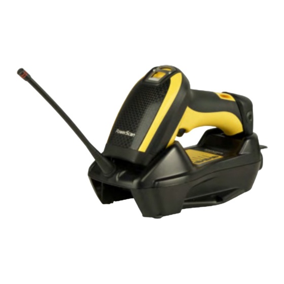
BC9180™
Base Station/Charger
Ethernet Base
Software Reference Guide
Table of
Contents
Previous
Page
Next
Page
1
2
3
4
5
Advertisement
Table of Contents
Need help?
Do you have a question about the BC9 0 Series and is the answer not in the manual?
Ask a question
Questions and answers
Subscribe to Our Youtube Channel
Related Manuals for Datalogic BC9 0 Series
Battery Charger Datalogic BC9 0-BT Series Quick Reference Manual
Base station/charger (33 pages)
Battery Charger Datalogic BC90-STAR Series Quick Reference Manual
Base station/charger (40 pages)
Battery Charger Datalogic BC9180 Software Reference Manual
Base station/charger ethernet base (60 pages)
Battery Charger Datalogic Memor 10 Quick Start Manual
Four slot battery charger (2 pages)
Battery Charger Datalogic MEMOR 11 Quick Start Manual
(2 pages)
Battery Charger Datalogic MC-P096 Quick Reference Manual
Multi-slot battery charger (2 pages)
Battery Charger Datalogic C-8000 Quick Reference Manual
(2 pages)
Battery Charger Datalogic C-GRYPHON Quick Reference Manual
(12 pages)
Battery Charger Datalogic SKORPIO Multi-Battery Charger Quick Start Manual
Multi-battery charger (1 page)
Battery Charger Datalogic SKORPIO X5 Quick Start Manual
4 slot battery charger (2 pages)
Battery Charger Datalogic CHR-PM80 Quick Reference Manual
(2 pages)
Battery Charger Datalogic DL-AXIST Four Slot Battery Charger Quick Start Manual
(2 pages)
Battery Charger Datalogic Datalogic Memor Quick Manual
Multi-battery charger (2 pages)
Battery Charger Datalogic C-3000 Quick Reference Manual
(2 pages)
This manual is also suitable for:
Bc9180
Table of Contents
Print
Rename the bookmark
Delete bookmark?
Delete from my manuals?
Login
Sign In
OR
Sign in with Facebook
Sign in with Google
Upload manual
Upload from disk
Upload from URL


Need help?
Do you have a question about the BC9 0 Series and is the answer not in the manual?
Questions and answers