
Related Manuals for Zodiac iAquaLink+ CONTROL Z350iQ


Summary of Contents for Zodiac iAquaLink+ CONTROL Z350iQ
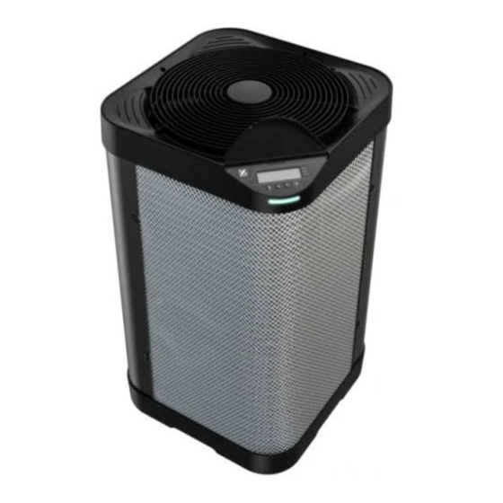
- Page 1 Z350iQ * Instructions for installation and use - English Heat pump Translation of the original instructions in French More documents on: www.zodiac.com H0791600_REVB - 2023/04...
- Page 3 • The distribution or modification of this document in any way is prohibited, without prior authorisation from the manufacturer. • Zodiac® is constantly developing its products to improve their quality. The information contained herein may therefore be modified without notice.
- Page 4 WARNINGS ASSOCIATED WITH ELECTRICAL APPLIANCES • The power supply to the appliance must be protected by a dedicated 30 mA Residual Current Device (RCD), complying with the standards and regulations in force in the country in which it is installed. •...
- Page 5 follow standard IEC/HD 60364-7-702 and required national rules for swimming pools. Consult your local dealer for more information. • The appliance may not be installed close to combustible materials, or the air duct inlet of an adjacent building. • During installation, troubleshooting and maintenance, pipes may not be used as steps: the pipe could break under the weight, spilling coolant and possibly causing serious burns.
- Page 6 concerning the equipment that is at hand and shall be suitable for the recovery of all appropriate refrigerants including, when applicable, flammable refrigerants. In addition, a set of calibrated weighing scales shall be available and in good working order. Hoses shall be complete with leak-free disconnect couplings and in good condition.
-
Page 7: Table Of Contents
CONTENTS ❶ Installation 1.1 I Selecting the location 1.2 I Hydraulic connections 1.3 I Electricity supply connections 1.4 I Option connections ❷ Use 2.1 I Operating principle 2.2 I User interface presentation 2.3 I Operation 2.4 I User functions 2.5 I Connecting to the iAqualink+™ app ❸... -
Page 8: ❶ Installation
❶ Installation 1.1 I Selecting the location 1.1.1 Installation precautions • The appliance should be installed at a distance of at least 2 metres from the edge of the pool. • Do not lift the appliance by the body; use its base. •... - Page 9 To rotate the user interface : Unscrew the 4 screws on the top cover. Lift the top cover and rotate it in the chosen position. CAUTION : The display board (under the display screen) is connected by a cable to the control board inside the unit. Handle the top cover carefully to do not damage this cable.
- Page 10 1.1.3 Recommendentions for selecting the appliance location • When installating the appliance, choose the hydraulic connectors that are best fitting the installation configuration between elbow connectors and straight connectors. • In a installation with the elbow connectors, position the appliance so that the connectors’ outlets run parallel to the wall.
-
Page 11: I Hydraulic Connections
Wall Wall 15cm 50 cm 50cm 50cm Installing the appliance in a corner 1.2 I Hydraulic connections • The device will be connected with a Ø50 PVC pipe, using the union connectors supplied (see § “5.1 I Description”), to the pool's filtration circuit, after the filter and before the water treatment. •... -
Page 12: I Electricity Supply Connections
• Provide free space around the appliance (see § “1.1.3 Recommendentions for selecting the appliance location”). • To evacuate the condensates, fit a Ø18 pipe on the grooved elbow to be mounted under the appliance base (supplied, see § ««5.1 I Description»). Condensate drainage orientation (seen from below the appliance) Tip: condensate drainage •... - Page 13 To access the electrical connection terminals and connect the unit to the power supply : Unscrew the 7 screws. Remove the lateral panel. Pass the power cable through bottom cable gland. x 7 screws Inside the appliance, pass the power cable through the bottom pre-created cable gland. To wire on the spring-cage terminal block: Pull the lever up as far as it will go, then connect the stripped (1cm) cable .
-
Page 14: I Option Connections
1.4 I Option connections Connecting the "Heating priority" and "Remote "On/off" control" options: • Before any work inside the appliance, you must cut the appliance’s electricity supply as there is a risk of electric shock which may cause material damage, serious injury or even death. •... -
Page 15: ❷ Use En
1.4.2 "Remote "On/Off" control" option • This option allows the "remote On/Off" function to be enabled by way of a switch installed remotely. • To connect, couple the remote "On/Off" switch (not provided) to terminals 3 - 4 (dry contact). : heat pump terminal board : remote "on/off"... -
Page 16: I User Interface Presentation
2.1.1 Precautions • Even though the appliance can be used all year round, certain precautions must be taken to avoid damaging the condenser (for the precautions specific to winterising, refer to § 3.1). • If the heat pump is subjected to extended exposure to negative outdoor temperatures (excluding winterising period), you must: - Activate the ‘‘Heating Priority’’... - Page 17 2.2.2 LED strip The LED strip on the front of the appliance gives you a rapid overview of the heat pump's operating status. The following table explains the meaning of the different strip lights. The front LED strip is lit by default. To switch it off, see «2.4.4 Using and selecting the different active operating modes».
-
Page 18: I Operation
2.3 I Operation • Check that there are no tools or other foreign objects in the machine. • The panel that provides access to the technical section must be put in place. • Check that the hydraulic corrections are correctly tightened and that there are no leaks. •... -
Page 19: I User Functions
2.4 I User functions 2.4.1 "Automatic keypad lock" function The "automatic keypad lock" function allows the keypad to be disabled when inactive for at least 30 seconds (default value) to prevent mishandling. Locking/unlocking the keypad: • Press simultaneously for 3 seconds. The indicator appears (= locked) or disappears (= unlocked) depending on the keypad's state. - Page 20 2.4.3 Activating/deactivating the "Cooling" mode Information: "Cooling" function • Activating the "Cooling" mode allows the machine's cycle to be automatically reversed to cool the pool water. • When the "Cooling" function is activated, as soon as the water temperature exceeds the setpoint temperature by more than 2°C (see following diagram), the heat pump automatically activates the "Cooling"...
- Page 21 2.4.4 Using and selecting the different active operating modes In “Heating” mode, the heat pump has 3 active operating modes for adjusting its operating speed to the power that is required and the mode that is selected. Depending on the selected operating mode (“BOOST”, “SMART” or “SILENCE”), the power delivered by the heat pump can vary over a predefined range (depending on the speed of its compressor and fan).
-
Page 22: I Connecting To The Iaqualink+™ App
2.5 I Connecting to the iAqualink+™ app Mobile device Home Wi-Fi network Heat pump The heat pump can be remotely controlled from a smartphone or tablet, via the iAqualink+™ app available for iOS and Android systems. Before connecting to the iAqualink+™ app, ensure that you: •... -
Page 23: ❸ Maintenance
❸ Maintenance 3.1 I Winterising • Winterising is vital to prevent the condenser breaking due to freezing. This is not covered by the warranty. • To avoid damaging the appliance with condensation, do not fully cover it; a winterising cover is provided. - Page 24 3.2.1 Safety instructions concerning appliances containing R32 refrigerant Area check • Prior to beginning work on systems containing flammable refrigerants, safety checks are necessary to ensure that the risk of ignition is minimised. Work procedure • Work shall be undertaken under a controlled procedure so as to minimise the risk of a flammable gas or vapour being present while the work is being performed.
- Page 25 atmosphere. The test apparatus shall be at the correct rating. • Replace components only with parts specified by the manufacturer. Other parts may result in the ignition of refrigerant in the atmosphere from a leak. Wiring • Check that cabling will not be subject to wear, corrosion, excessive pressure, vibration, sharp edges or any other adverse environmental effects.
-
Page 26: ❹ Troubleshooting
3.2.2 User maintenance • Make sure that the grid on the top cover is not blocked by any foreign bodies. • Clean the evaporator (for location see § “5.3 I Dimensions and marking”) using a soft brush and a fresh water spray (disconnect the power cable);... -
Page 27: I Error Code Display
• The operating mode is not powerful enough (appliance in "SILENCE" or "SMART" mode). Switch to "BOOST" mode and set the filtration to 24/24 manual while the temperature rises. • The appliance may have detected an operating fault (see § “4.2 I Error code display”). The appliance •... - Page 28 Display Possible causes Possible Solutions Bad connection between Check the RJ45 cables between A1 - A5 and Communication fault the boards A1 - A2 - A5 A2 - A5 between the regulation board and the display board Faulty boards Replace the boards Electronic board’s radiator Check the condition of the radiator to the rear of the clogged...
- Page 29 E18 followed by a number - driver trip Display sequence « E18 » / « # » : Actions to be performed by a qualified technician only Description Possible causes Possible solutions Communication fault with master controller Out-of-speed fault Driver is damaged Replace the driver board Compressor and PFC key data fault (can not be...
-
Page 30: I Lighting Of Leds On The Printed Circuit Board
4.3 I Lighting of LEDs on the printed circuit board LED5 LED4 LED3 LED2 LED1 No errors Appliance switched on Error 04 Error 05 Error 06 Error 07 Error 08 Error 09 Error 10 Error 11 Error 12 Error 14 Error 15 Error 16 Error 17... -
Page 31: I Wiring Diagrams
4.4 I Wiring diagrams... - Page 32 Symbol Description Electronic regulation board Display board (HMI) Compressor and fan driving electronic board (driver) Black Blue Brown Compressor Electronic expansion valve F1 - F2 Fuse Fan motor Green/Yellow High pressure switch Orange Pink Water flow regulation sensor Anti-freeze sensor Defrost sensor Liquid line temperature sensor Compressor discharge temperature sensor...
-
Page 33: ❺ Characteristics
❺ Characteristics 5.1 I Description Z350iQ Ø50 elbow connectors (x2) and straight connectors (x2) Condensate drainage kit (Ø18) Winterising cap (x2) Winterising cover PAC NET (cleaning product) : Included : Available as an accessory... -
Page 34: I Technical Data
5.2 I Technical data Z350iQ Performances: air at 28°C / water at 28°C / humidity at 80 % Power output (max-min 11 - 3.1 14 - 4.4 16 - 4.7 speed) Power consumed (max-min 1.9 - 0.3 2.6 - 0.5 3.2 - 0.5 speed) Average COP (max-min speed) -
Page 35: I Dimensions And Marking
5.3 I Dimensions and marking TOLLER.GEN. TOLLER.GEN. 00/00 MOD/REV: Bottom 00/00 MOD/REV: DATA MODIF. DATA MODIF. ESEGUITA ESEGUITA APPROVATA APPROVATA SCALA 1:10 SCALA 1:10 DATA 1aEMISS. DATA 1aEMISS. ESEGUITO ESEGUITO APPROVATO APPROVATO Firma Firmato in IMPIEGO IMPIEGO Front Rear Grid LED strip User interface Technical access door... - Page 36 Serial number For more information, product registration and customer support: www.zodiac.com ©2023 Zodiac Pool Systems LLC. All rights reserved. ZODIAC® is a registered trademark of Zodiac International, S.A.S.U., used under license. All other trademarks are the property of their respective owners.
Need help?
Do you have a question about the iAquaLink+ CONTROL Z350iQ and is the answer not in the manual?
Questions and answers