Advertisement
Quick Links
Advertisement

Subscribe to Our Youtube Channel
Related Manuals for Saswell T21STK-2


Summary of Contents for Saswell T21STK-2
- Page 1 T21STK-2 OPERATING INSTRUCTION...
- Page 2 T21STK-2 SINGLE STAGE PROGRAMMABLE THERMOSTAT 1 Heat / 1 Cool single stage thermostat. 5+2 Programmable, Compatible with heat pump system Installation and Operation Manual Specification:-------------------------------------------------------------------------------- Power Supply: 20VAC-30VAC 50-60HZ or Battery powered. Terminal Load: 1.0A per terminal, 3.0A maximum total load Set Point Temperature Range: 45ºF to 90ºF (7ºC to 32ºC).
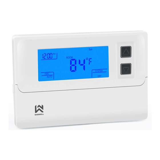
- Page 3 FEATURES:--------------------------------------------------------------------------------- Large LCD display with backlight, continuous backlight option Simultaneous heat and cool set point storage Display of room temperature, set temperature and current time simultaneously Fan switch with ON and AUTO Permanent user setting retention during power loss. No batteries are required. ...
- Page 4 four separate time/temperature periods per day. Intelligent Recovery Option for optimizing comfort IMPORTANT SAFETY INFORMATION------------------------------------------- Always turn off power at the main power source by removing the fuse, or switching the circuit breaker to the off position before installing, removing, cleaning, or servicing this thermostat.
- Page 5 Do not short (jumper) across terminals on the gas valve or at the system control to test installation. This will damage the thermostat and void the warranty. Do not switch the system to cool if the temperature is below 50ºF (10ºC). This can damage the air conditioning system and may cause personal injury.
- Page 6 Turn off power to the heating and cooling system by removing the fuse or switching the appropriate circuit breaker off. Remove the cover of the old thermostat. This should expose the wires. Label the existing wires from the existing thermostat before removing. After labeling the wires, remove the wires from the wire terminals.
- Page 7 INSTALL THE THERMOSTAT--------------------------------------------------------------------------------- ATTACH THERMOSTAT BASE TO WALL PULL THE COVER OFF THE BASE.
- Page 8 WARNING!: Electrical Shock Hazard Turn off power at the main service panel by removing the fuse or switching the appropriate circuit breaker to the OFF position before removing the existing thermostat. Turn off power to the heating and cooling system by removing the fuse or switching the appropriate circuit breaker off.
- Page 9 Fasten the base loosely to the wall as shown in Figure 1, using two mounting screws. Place a level against the bottom of the base and adjust until level, then tighten the screws. (Leveling is for appearance only, and will not affect thermostat operation.) Insert stripped, labeled wires into matching wire terminals.
- Page 10 Install two fresh “AA” alkaline batteries in the battery compartment. Be sure to match positive (+) ends of batteries with positive (+) battery terminals in the battery compartment. (The thermostat will operate from 2 size “AA” alkaline batteries or 24VAC power. When operated from 24VAC power, your thermostat will maintain time and continuously display the temperature during a loss of AC power with the batteries installed.) Replace the cover on the thermostat by snapping it in place.
-
Page 11: Battery Operation
This thermostat is configured from the factory to energize the fan on a call for heat. If your system is an electric heat or heat pump that REQUIRES the thermostat to turn on the fan on a call for heat, place the fan option switch in the ELEC position. If your system does not require the thermostat to energize the fan on a call for heat such as fossil fuel (gas, oil, etc.), forced air system as well as hydraulic heating systems, place the fan option switch in the GAS position. - Page 12 Wiring Diagrams Figure 3, Typical wiring diagram for heat/cool, 5 wire two transformer system.
- Page 13 Figure 4, Typical wiring diagram for heat/cool, 4 wire, single transformer system...
- Page 14 Note* Jumper required in heat pump mode. Figure 5, Typical wiring diagram for heat pump with reversing valve...
- Page 15 CHECK THERMOSTAT OPERATION------------------------------------------------------------------ If at any time during testing your system does not operate properly, contact a qualified service person. Turn on power to the system. Fan Operation Move the system switch to the OFF position. If your system does not have a “G” (Fan) terminal connection, skip to the Heating System.
- Page 16 When the (FA)st heating cycle rate is selected in the configuration menu, (see configuration menu item 2), the thermostat will call for heat at 0.5ºF (0.5ºC) below set-point, and turn off at set point. When the (SL)ow heating cycle rate is selected, the thermostat will call for heat at 1.5ºF (1.5ºC) below set-point, and turn off at set-point.
- Page 17 When the (FA)st cooling cycle rate is selected in the configuration menu, (see configuration menu item 2), the thermostat will call for cooling at 0.5ºF (0.5ºC) above set-point, and turn off set point. When the (SL)ow cool cycle rate is selected, the thermostat will call for cooling at 1.5ºF (1.5ºC) above set-point, and turn off at set-point.
- Page 18 expire. Then the thermostat will cut power to the heating/cooling system. Important: Replace the batteries when the low battery message flashes on the display. This will keep the thermostat operating properly. With two “AA” batteries installed, your thermostat will maintain time and continuously display the temperature during a loss of AC power.
- Page 19 Configuration Menu The configuration menu allows you to set certain thermostat operating characteristics to your system or personal requirements. Move the SYSTEM switch to the OFF position, then press and hold the PRGM and RUN buttons for 3 seconds to enter the configuration menu. The display will show the first item in the configuration menu.
- Page 21 Select cooling cycle rate The FA setting is used to produce shorter cooling cycles. The SL setting produces a longer cooling cycle. Both settings produce very accurate temperature control and can be set to your personal preference. FA cycles the system at a 0.5ºF (0.5ºC) differential, and SL cycles the system at 1.5ºF (1.5ºC).
- Page 22 Select system heating type Users can select the system heating type according to their heating system. Select 0 for gas, oil, or electric heating systems. Select 1 for a heat pump heating system. Select display backlight The display backlight improves display contrast in low lighting conditions. Select 1 for NO backlight display.
- Page 23 Select filter replacement run time The thermostat will display the Filter Alarm after a set time of operation. This is a reminder to change or clean your air filter. This time can be set from 0 to 12 months in 1 month increments. Selection of 00 WILL CANCEL THIS FEATURE.
- Page 24 Select compressor lockout delay To protect the compressor from short cycling, you can select compressor off-time cycle between 0 or 5 minutes. When the thermostat compressor time delay occurs, the Cool On or Heat On display will flash during compressor lockout.
-
Page 25: Thermostat Operation
THERMOSTAT OPERATION Setting the thermostat This thermostat is very easy to operate. Set the SYSTEM switch to either HEAT or COOL, then press the ▲ or ▼ buttons until the temperature you want to maintain is shown on the right side of the display. - Page 26 Press the ▲ or ▼ buttons until you reach the correct day of the week. Press the TIME button again. The display will now indicate the correct time and day of the week. Filter timer a) When in configuration the selections are in months, each month selections are equal to 30 days.
-
Page 27: Manual Operation
MANUAL OPERATION Hold Temperature With the SYSTEM switch set to HEAT or COOL, momentarily press the HOLD button. HOLD will be displayed. Use the ▲ or ▼ buttons to adjust the temperature. The thermostat will control the room temperature at the selected setting until you press the RUN button to restart the program operation. - Page 28 Planning your program Note: The time of day clock MUST be set to the correct day and time in order for the programmed times to be correct. Look at the factory preprogrammed times and temperatures shown in the Factory default program setting.
- Page 29 during each period. Fill in the completed table to have a record of your program. EXAMPLE: Heating/Cooling Schedule Plan (Factory default program setting)
- Page 30 Heating/Cooling Schedule Plan Enter the Heating Program 1) Move the SYSTEM switch to the HEAT position. 2) Press PRGM once. PRGM SETTING will display, and “MON TUE WED THU FRI” (indicating weekday program) will appear in the display (flashing). Also displayed are the current programmed start time for the 1 heating period (flashing),and the currently programmed temperature.
- Page 31 3) Press the ▲ or ▼ buttons to select the desired 1 heating period start time. The time will change in 15 minute increments. When your selected time is displayed, press the TIME button to change to the temperature mode. 4) Press the ▲...
- Page 32 (flashing),and the currently programmed temperature. 9) Repeat steps 3 thru 7 to complete Saturday and Sunday programming. 10) When you have completed entering your heating program, press RUN. Thermostat Buttons and Switches Enter the Cooling Program Caution! If the outside temperature is below 50ºF; disconnect power to the cooling system before programming.
- Page 33 Check your programming Follow these steps to check your thermostat programming one final time before beginning thermostat operation: 1) Move the SYSTEM switch to HEAT. 2) Press PRGM to view the 1 weekday heating period time and temperature. Each time you press PRGM the next heating period time and temperature will be displayed in sequence for weekday, then Saturday and Sunday program periods (you may change any time or temperature during this procedure).
- Page 34 6) Move the SYSTEM switch to HEAT or COOL and press RUN to begin program operation. REVERT TO FACTORY DEFAULT PROGRAM SETTINGS Press the RESET button. All user’s changed settings will revert to factory default settings (Including configuration settings). Troubleshooting-------------------------------------------------------------------------------- If a voltage spike or static discharge blanks out the display or causes erratic thermostat operation, you can reset the thermostat by pressing the reset button (See Figure 1).
- Page 35 THERMOSTAT LCD DISPLAY Figure 2...
-
Page 36: Thermostat Buttons And Switches
THERMOSTAT BUTTONS AND SWITCHES Figure 3... - Page 37 Troubleshooting If a voltage spike or static discharge blanks out the display or causes erratic operation, you can reset the thermostat by pressing the reset button (see figure 1). If the thermostat haw power, has been reset and still does not function correctly, contact your heating/cooling service person or place...
Need help?
Do you have a question about the T21STK-2 and is the answer not in the manual?
Questions and answers