Advertisement
Advertisement
Table of Contents

Related Manuals for Saswell T21HTW-0


Summary of Contents for Saswell T21HTW-0
- Page 1 T21HTW-0 OPERATING INSTRUCTION...
-
Page 2: Specification
This manual apply for T21HTW-0, used with 2 Heat / 1 Cool & emergency Heat Non Programmable, Compatible with heat pump system SPECIFICATION Power Supply ………………………20VAC-30VAC 50-60Hz or Battery powered. Terminal Load…………………………1.0 A per terminal, 3.0A maximum total load Set point Temperature Range………….45 º... -
Page 3: Important Safety Information
Low Battery Indicator. Temperature calibration. Batteries required to maintain clock function. Compressor short cycling protection available B and O terminals available. IMPORTANT SAFETY INFORMATION Always turn off power at the main power source by unscrewing fuse or switching circuit breaker to the off position before installing, removing, cleaning, or servicing this thermostat. -
Page 4: Remove The Old Thermostat
Replace batteries when the battery icon indicates the low battery message. Change the Air Filter when the Filter Change Icon begins blinking. Use this thermostat only as described in this manual. REMOVE THE OLD THERMOSTAT WARNING ! Electrical Shock Hazard 1. -
Page 5: Install The Thermostat
INSTALL THE THERMOSTAT Push the button to open Installing the screws in the base cover thermostat front cover into the junction box and finish wiring Close the lid then fitting the 2AA Battery push up the slide cover Figure 1... - Page 6 WARNING ! Electrical Shock Hazard Turn off power at the main service panel by removing the fuse or switching the appropriate circuit breaker to the OFF position before removing the existing thermostat. 1. Turn off power to the heating and cooling system by removing the fuse or switching the appropriate circuit breaker off.
- Page 7 10. Tighten screws on terminal block. Gently tug on each wire to be sure of proper connection. Double check that each wire is connected to the proper terminal. CAUTION: Installing batteries backwards can damage the thermostat. 11. Install two fresh “AA” alkaline batteries in the battery compartment. Be sure to match positive (+) ends of batteries with positive (+) battery terminals in the battery compartment (The thermostat will not operate from 2 size “AA”...
-
Page 8: Wiring Diagram
BATTERY OPERATION With two “AA” batteries installed, your thermostat will maintain time and continuously display the temperature during a loss of AC power. The LCD Backlight will not function when AC power is lost. If the battery icon on the display is flashing, it indicates that the batteries need to be replaced. When the thermostat is powered only by battery, the battery icon will flash for approximately 2 months before the batteries are expected to expire. -
Page 9: Check Thermostat Operation
* NOTE:Jumper wire required to use a single Aux Heat for both AUX Heating and Emergency Heating. NOTE** When presented with 24VAC on the “L” terminal, the Alarm Icon will flash on the display. CHECK THERMOSTAT OPERATION If at any time during testing your system does not operate properly, contact a qualified service person. Heating system Turn on power to the system. - Page 10 set-point. When the thermostat calls for heat, the display will show Heat On. If the Heat On display is flashing, the compressor lockout feature is operating in the heat pump mode. (Note: See Configuration menu item 7). The Aux heating will activate when the room temperature is 2° F (1.0° C) below setpoint temperature. When Aux heating turns on, AUX 1+2 will be displayed.
- Page 11 Emergency Heating System EMER by passes the HEAT PUMP to use the heat source connected to terminal E on the thermostat. EMER is typically used when compressor operation is not desired, or you prefer to use the back-up heating system only. 1.
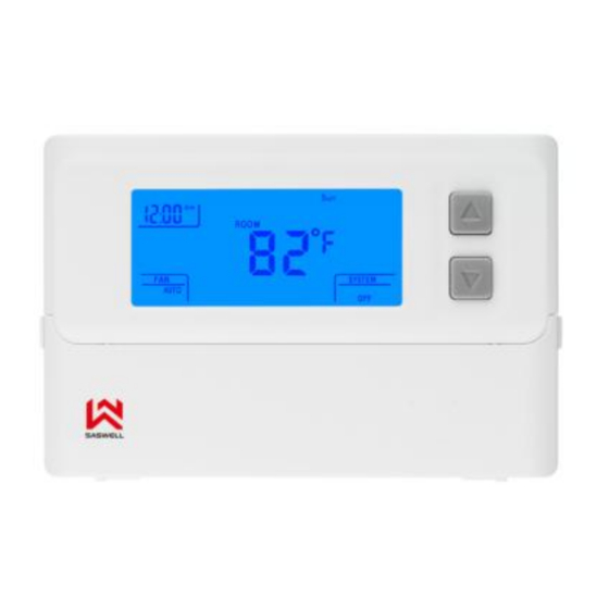
- Page 12 THERMOSTAT LCD DISPLAY R oom S et t ing Time s et t ing Temperat ure Temperat ure E mergenc y heat H eat ing A ux heat ing C ooling On A ut o C ompres s or prot ec t ion Low B at t ery indic at e Mode Timer delay...
-
Page 13: Thermostat Operation
THERMOSTAT BUTTONS AND SWITCHES 1 Raises or lowers the temperature setting OFF mode Selects options in the configuration menu. 3 OFF mode Hold the down button enter into clock setting mode Fan control switch (On /Auto /HEAT System control switch (EMER /OFF/ COOL User setting reset... -
Page 14: Troubleshooting
2. Clock setting Move the SYSTEM switch to the OFF position, then press and hold the ▼ buttons for 5 seconds to enter the clock setting mode. The display will show the HOUR setting first . Use the ▲ button to select each user setting. Press the ▼... - Page 15 1. Select cooling cycle rate The FA setting is used to produce shorter cooling cycles. The SL setting produces a longer cooling cycle. Both settings produce very accurate temperature control and can be set to your personal preference. FA cycles the system at a 0.5º...
- Page 16 5. Select º F or º C readout Changes the display readout to Centigrade or Fahrenheit as required. 6. Select temperature recalibration This feature allows you to adjust the displayed room temperature up to 4º higher or lower. Your thermostat can be accurately calibrated to match your previous thermostat.
-
Page 17: Configuration And Operation
CONFIGURATION AND OPERATION The configuration menu allows you to set certain thermostat operating characteristics to your system or personal requirements. Move the SYSTEM switch to the OFF position, then press and hold the ▲ and ▼ buttons for 5 seconds to enter the configuration menu. The display will show the first item in the configuration menu. Press the ▼ button to shift to the next menu item. - Page 18 Select display backlight (1) = OFF, (2) = 30 seconds on any button push, (3) = ON. Default 1 – 3 ▼ bL (2) = 2. Option (3) can be activated only if the common is used. Select filter time in months. Default = 00. ▼...
-
Page 19: Customer Assistance
CUSTOMER ASSISTANCE After reading this guide, if you have any question about the operation of your thermostat,please contact your installer or Energy Utility company or service provider.
Need help?
Do you have a question about the T21HTW-0 and is the answer not in the manual?
Questions and answers