Table of Contents
Advertisement
Quick Links
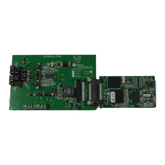
This user guide describes the operation and usage of the ADS86xx evaluation module (EVM). The
ADS86xx are a family of pin-compatible successive approximation (SAR) analog-to-digital converters
(ADCs) with varying resolution and channel counts designed for integrated data acquisition systems.
Table 1
lists the devices available in the ADS86xx family that are supported by the ADS86xxEVM.
Device
ADS8698
ADS8688A
ADS8678
ADS8668
Windows is a registered trademark of Microsoft Corporation.
SPI is a trademark of Motorola Mobility LLC.
Samtec is a trademark of Samtec Inc.
All other trademarks are the property of their respective owners.
SBAU245A – June 2015 – Revised July 2015
Submit Documentation Feedback
ADS86xxEVM-PDK Evaluation Module
ADS86xxEVM-PDK
Table 1. Devices Supported By the ADS86xxEVM
8-channel, integrated, 18-bit SAR ADC with ALARM
8-channel, integrated, 16-bit SAR ADC with ALARM
8-channel, integrated, 14-bit SAR ADC with ALARM
8-channel, integrated, 12-bit SAR ADC with ALARM
Copyright © 2015, Texas Instruments Incorporated
User's Guide
SBAU245A – June 2015 – Revised July 2015
Description
ADS86xxEVM-PDK Evaluation Module
1
Advertisement
Table of Contents

Related Manuals for Texas Instruments ADS86 EVM-PDK Series


Summary of Contents for Texas Instruments ADS86 EVM-PDK Series
-
Page 1: Devices Supported By The Ads86Xxevm
SPI is a trademark of Motorola Mobility LLC. Samtec is a trademark of Samtec Inc. All other trademarks are the property of their respective owners. SBAU245A – June 2015 – Revised July 2015 ADS86xxEVM-PDK Evaluation Module Submit Documentation Feedback Copyright © 2015, Texas Instruments Incorporated... -
Page 2: Table Of Contents
Register Map View ..................ADS86xxEVM Jumper Settings ....................Manual Mode Data Capture ..............Data Capture in Auto Mode with Single Graph View ADS86xxEVM-PDK Evaluation Module SBAU245A – June 2015 – Revised July 2015 Submit Documentation Feedback Copyright © 2015, Texas Instruments Incorporated... - Page 3 Jumper Settings for Generating HVDD and HVSS from External High-Voltage Supplies ....................Power-Supply Connections ..................... Default Jumper Configuration ..................ADS8688EVM Bill of Materials SBAU245A – June 2015 – Revised July 2015 ADS86xxEVM-PDK Evaluation Module Submit Documentation Feedback Copyright © 2015, Texas Instruments Incorporated...
-
Page 4: Related Documents
Related Documents Table 2 lists the related documents that are available through the Texas Instruments web site at www.ti.com. The ADS86xxEVM is designed to demonstrate true performance of these devices. Each input channel on the selected device can support true bipolar input ranges of ±10.24 V, ±5.12 V, and ±2.56 V as well as unipolar input ranges of 0 V to 10.24 V and 0 V to 5.12 V. -
Page 5: Ads86Xxevm-Pdk Overview
Provides single and multiple graph views for captured data. • Includes a dc histogram for dc inputs. • Logs ADC data. SBAU245A – June 2015 – Revised July 2015 ADS86xxEVM-PDK Evaluation Module Submit Documentation Feedback Copyright © 2015, Texas Instruments Incorporated... -
Page 6: Evm Analog Interface
Figure 1. ADS86xxEVM Analog Input Connections for Channels AIN0, AIN1, AIN2, and AIN3 Figure 2. ADS86xxEVM Analog Input Connections for Channels AIN4, AIN5, AIN6, and AIN7 ADS86xxEVM-PDK Evaluation Module SBAU245A – June 2015 – Revised July 2015 Submit Documentation Feedback Copyright © 2015, Texas Instruments Incorporated... -
Page 7: Connecting Negative Inputs To Ground
A3– Closed Open A4– Closed Open A5– Closed Open A6– Closed Open A7– Closed Open AUX– Always connected to GND SBAU245A – June 2015 – Revised July 2015 ADS86xxEVM-PDK Evaluation Module Submit Documentation Feedback Copyright © 2015, Texas Instruments Incorporated... -
Page 8: Using Onboard, Second-Order, Butterworth, Low-Pass Filters
Closed Open Table 8. External Reference Connections Number Signal Description J5.1 REFIN Input for external reference J5.2 Analog ground connection ADS86xxEVM-PDK Evaluation Module SBAU245A – June 2015 – Revised July 2015 Submit Documentation Feedback Copyright © 2015, Texas Instruments Incorporated... -
Page 9: Digital Interface
The ADS86xxEVM has a microSD card that contains the software files for the simple capture card. The contents of the microSD card must not be deleted or altered. SBAU245A – June 2015 – Revised July 2015 ADS86xxEVM-PDK Evaluation Module Submit Documentation Feedback Copyright © 2015, Texas Instruments Incorporated... -
Page 10: Power Supplies
EXT_HVSS –16 V to –25 V J18.1 high-voltage supplies. Make sure HVDD + |HVSS| < 36 V. — J18.2 — ADS86xxEVM-PDK Evaluation Module SBAU245A – June 2015 – Revised July 2015 Submit Documentation Feedback Copyright © 2015, Texas Instruments Incorporated... -
Page 11: Power-Supply Connections Diagram
REG71055 charge pump and the TPS7A4901 linear regulator. The DVDD digital supply for the ADC is derived from a 3.3-V supply from the simple capture card. SBAU245A – June 2015 – Revised July 2015 ADS86xxEVM-PDK Evaluation Module Submit Documentation Feedback Copyright © 2015, Texas Instruments Incorporated... -
Page 12: Ads86Xxevm-Pdk Initial Setup
Figure 4 details the default jumper settings. Table 13 provides the configuration for these jumpers. Figure 4. ADS86xxEVM Default Jumper Settings ADS86xxEVM-PDK Evaluation Module SBAU245A – June 2015 – Revised July 2015 Submit Documentation Feedback Copyright © 2015, Texas Instruments Incorporated... -
Page 13: Software Installation
3. Install the ADS86xxEVM-PDK software. 4. Complete the simple capture card device driver installation. Each task is described in the following subsections. SBAU245A – June 2015 – Revised July 2015 ADS86xxEVM-PDK Evaluation Module Submit Documentation Feedback Copyright © 2015, Texas Instruments Incorporated... -
Page 14: Bottom View Of The Simple Capture Card With The Microsd Memory Card Installed
2. Ensure that the ADS86xxEVM jumpers are configured as illustrated in Figure 3. Connect the ADS86xxEVM board to the simple capture card; see Figure ADS86xxEVM-PDK Evaluation Module SBAU245A – June 2015 – Revised July 2015 Submit Documentation Feedback Copyright © 2015, Texas Instruments Incorporated... -
Page 15: Connecting The Ads86Xxevm Board To The Simple Capture Card
3. Run the installer by double-clicking the setup.exe file. This action installs the EVM GUI software and required simple capture card device driver components. 4. After the installer begins, a welcome screen is displayed. Click Next to continue. 5. Select the default directory under: ...\Program Files(x86)\Texas Instruments\ADS86XX EVM GUI\; see Figure 9 Figure 10. -
Page 16: Destination Directory Screen
Figure 9. Destination Directory Screen Figure 10. License Agreement Screen 6. Select the I Accept the License Agreement radial button and click Next. ADS86xxEVM-PDK Evaluation Module SBAU245A – June 2015 – Revised July 2015 Submit Documentation Feedback Copyright © 2015, Texas Instruments Incorporated... -
Page 17: Start Installation Screen
12; this step takes a few minutes. Figure 12. Progress Bar Screen 9. The progress bar is followed by an installation complete notice. SBAU245A – June 2015 – Revised July 2015 ADS86xxEVM-PDK Evaluation Module Submit Documentation Feedback Copyright © 2015, Texas Instruments Incorporated... -
Page 18: Windows 7 Driver Installation Warning
2. A computer restart may be required to finish the software installation. If prompted, restart the computer to complete the installation. Figure 14. Installation Wizard Screen Figure 15. Simple Capture Card Device Driver Completion ADS86xxEVM-PDK Evaluation Module SBAU245A – June 2015 – Revised July 2015 Submit Documentation Feedback Copyright © 2015, Texas Instruments Incorporated... -
Page 19: Ads86Xxevm-Pdk Kit Operation
Section 6.2.2. Step 2. Start the ADS86xxEVM GUI. Go to Start→All Programs→Texas Instruments→ADS86xx EVM GUI and click ADS86xx EVM GUI to run the software. Step 3. Verify that the software detects the ADS86xxEVM. The GUI identifies the device on the EVM that is connected to the controller and loads the settings. -
Page 20: Configuring The Ads86Xxevm
Figure Figure 17. System Block Diagram View Figure 18. Selecting the Input Range for the Channels ADS86xxEVM-PDK Evaluation Module SBAU245A – June 2015 – Revised July 2015 Submit Documentation Feedback Copyright © 2015, Texas Instruments Incorporated... -
Page 21: Register Map View
For details on the ADS86xx program registers, refer to the program register map in the respective device data sheet. Figure 19 shows the register map view. Figure 19. Register Map View SBAU245A – June 2015 – Revised July 2015 ADS86xxEVM-PDK Evaluation Module Submit Documentation Feedback Copyright © 2015, Texas Instruments Incorporated... -
Page 22: Capturing The Data
2. The data captured are displayed in a graph in the GUI window. ADS86xxEVM-PDK Evaluation Module SBAU245A – June 2015 – Revised July 2015 Submit Documentation Feedback Copyright © 2015, Texas Instruments Incorporated... -
Page 23: Manual Mode Data Capture
In multi graph view, data for all enabled channels are displayed in multi graph view. Figure 22 Figure 23 illustrate the data captured in auto mode. SBAU245A – June 2015 – Revised July 2015 ADS86xxEVM-PDK Evaluation Module Submit Documentation Feedback Copyright © 2015, Texas Instruments Incorporated... -
Page 24: Data Capture In Auto Mode With Single Graph View
Figure 22. Data Capture in Auto Mode with Single Graph View Figure 23. Data Capture in Auto Mode with Multi Graph View ADS86xxEVM-PDK Evaluation Module SBAU245A – June 2015 – Revised July 2015 Submit Documentation Feedback Copyright © 2015, Texas Instruments Incorporated... -
Page 25: Saving The Captured Data
24. A window appears for selecting the location and entering the name of the file for saving the captured data. Figure 24. Saving the Captured Data SBAU245A – June 2015 – Revised July 2015 ADS86xxEVM-PDK Evaluation Module Submit Documentation Feedback Copyright © 2015, Texas Instruments Incorporated... -
Page 26: Analyzing The Data
Sigma: Is the standard deviation of all the codes captured. • Mean: Is the average of all the codes captured for a certain input. ADS86xxEVM-PDK Evaluation Module SBAU245A – June 2015 – Revised July 2015 Submit Documentation Feedback Copyright © 2015, Texas Instruments Incorporated... -
Page 27: Fft Analysis
The GUI analyses the FFT to provide signal power (dBFs), SNR, SINAD, THD, SFDR, and ENOB numbers. • The GUI uses a 7-term Blackman-Harris window to minimize spectral leakage. SBAU245A – June 2015 – Revised July 2015 ADS86xxEVM-PDK Evaluation Module Submit Documentation Feedback Copyright © 2015, Texas Instruments Incorporated... -
Page 28: Alarm Feature
The user can also program these values by individually programming each register from register map view, as described in Section 7.3.2. Figure 27. Alarm Enable Settings ADS86xxEVM-PDK Evaluation Module SBAU245A – June 2015 – Revised July 2015 Submit Documentation Feedback Copyright © 2015, Texas Instruments Incorporated... -
Page 29: Phase Compensation
The phase compensation analysis page can be activated from the Smart App menu. Figure 28 displays the phase compensation analysis page. SBAU245A – June 2015 – Revised July 2015 ADS86xxEVM-PDK Evaluation Module Submit Documentation Feedback Copyright © 2015, Texas Instruments Incorporated... -
Page 30: Phase Compensation Analysis
ADS86xxEVM-PDK Kit Operation www.ti.com Figure 28. Phase Compensation Analysis ADS86xxEVM-PDK Evaluation Module SBAU245A – June 2015 – Revised July 2015 Submit Documentation Feedback Copyright © 2015, Texas Instruments Incorporated... -
Page 31: Ads86Xxevm Gui Simulation Mode
ADS86xxEVM board and only displays the results for one set of captured data stored in the computer. Figure 29 shows the ADS86xxEVM GUI running in simulation mode. Figure 29. Simulation Mode SBAU245A – June 2015 – Revised July 2015 ADS86xxEVM-PDK Evaluation Module Submit Documentation Feedback Copyright © 2015, Texas Instruments Incorporated... -
Page 32: Bill Of Materials, Layout, And Schematics
C9, C63 CAP, CERM, 1uF, 16V, +/-10%, X7R, 0603 C1608X7R1C105K Diode, LED, RED, 2.1V, 14.2-mcd, 20 mA, 0805 Lite On LTST-C170UKT ADS86xxEVM-PDK Evaluation Module SBAU245A – June 2015 – Revised July 2015 Submit Documentation Feedback Copyright © 2015, Texas Instruments Incorporated... - Page 33 Vishay-Dale CRCW0402499KFKED R59, R73 RES, 20k ohm, 5%, 0.063W, 0402 Vishay-Dale CRCW040220K0JNED RES, 33k ohm, 5%, 0.063W, 0402 Vishay-Dale CRCW040233K0JNED SBAU245A – June 2015 – Revised July 2015 ADS86xxEVM-PDK Evaluation Module Submit Documentation Feedback Copyright © 2015, Texas Instruments Incorporated...
- Page 34 Input and 0.8 to 58 V Output, -40 to 150 degC, 10-Pin MSOP- Texas Instruments TPS54060DGQ PowerPAD (DGQ), Green (RoHS & no Sb/Br) ADS86xxEVM-PDK Evaluation Module SBAU245A – June 2015 – Revised July 2015 Submit Documentation Feedback Copyright © 2015, Texas Instruments Incorporated...
-
Page 35: Board Layouts
NOTE: Board layouts are not to scale. These figures are intended to show how the board is laid out; these figures are not intended to be used for manufacturing ADS86xxEVM PCBs. Figure 30. ADS86xxEVM PCB: Top Layer (L1) SBAU245A – June 2015 – Revised July 2015 ADS86xxEVM-PDK Evaluation Module Submit Documentation Feedback Copyright © 2015, Texas Instruments Incorporated... -
Page 36: Ads86Xxevm Pcb: Ground Layer (L2)
Bill of Materials, Layout, and Schematics www.ti.com Figure 31. ADS86xxEVM PCB: Ground Layer (L2) Figure 32. ADS86xxEVM PCB: Analog Power Layer (L3) ADS86xxEVM-PDK Evaluation Module SBAU245A – June 2015 – Revised July 2015 Submit Documentation Feedback Copyright © 2015, Texas Instruments Incorporated... -
Page 37: Ads86Xxevm Pcb: Digital Power Layer (L4)
Bill of Materials, Layout, and Schematics www.ti.com Figure 33. ADS86xxEVM PCB: Digital Power Layer (L4) Figure 34. ADS86xxEVM PCB: Ground Layer (L5) SBAU245A – June 2015 – Revised July 2015 ADS86xxEVM-PDK Evaluation Module Submit Documentation Feedback Copyright © 2015, Texas Instruments Incorporated... -
Page 38: Ads86Xxevm Pcb: Bottom Layer (L6)
Bill of Materials, Layout, and Schematics www.ti.com Figure 35. ADS86xxEVM PCB: Bottom Layer (L6) ADS86xxEVM-PDK Evaluation Module SBAU245A – June 2015 – Revised July 2015 Submit Documentation Feedback Copyright © 2015, Texas Instruments Incorporated... -
Page 39: Schematics
Bill of Materials, Layout, and Schematics www.ti.com Schematics Figure 36 Figure 37 illustrate schematics for the ADS86xxEVM-PDK. Figure 36. ADS86xx Interface Schematic SBAU245A – June 2015 – Revised July 2015 ADS86xxEVM-PDK Evaluation Module Submit Documentation Feedback Copyright © 2015, Texas Instruments Incorporated... -
Page 40: Power And Sdcc Interface Schematic
Bill of Materials, Layout, and Schematics www.ti.com Figure 37. Power and SDCC Interface Schematic ADS86xxEVM-PDK Evaluation Module SBAU245A – June 2015 – Revised July 2015 Submit Documentation Feedback Copyright © 2015, Texas Instruments Incorporated... - Page 41 Section 8 ......................• Added Schematics section NOTE: Page numbers for previous revisions may differ from page numbers in the current version. SBAU245A – June 2015 – Revised July 2015 Revision History Submit Documentation Feedback Copyright © 2015, Texas Instruments Incorporated...
- Page 42 STANDARD TERMS AND CONDITIONS FOR EVALUATION MODULES Delivery: TI delivers TI evaluation boards, kits, or modules, including any accompanying demonstration software, components, or documentation (collectively, an “EVM” or “EVMs”) to the User (“User”) in accordance with the terms and conditions set forth herein. Acceptance of the EVM is expressly subject to the following terms and conditions.
- Page 43 FCC Interference Statement for Class B EVM devices NOTE: This equipment has been tested and found to comply with the limits for a Class B digital device, pursuant to part 15 of the FCC Rules. These limits are designed to provide reasonable protection against harmful interference in a residential installation.
- Page 44 【無線電波を送信する製品の開発キットをお使いになる際の注意事項】 開発キットの中には技術基準適合証明を受けて いないものがあります。 技術適合証明を受けていないもののご使用に際しては、電波法遵守のため、以下のいずれかの 措置を取っていただく必要がありますのでご注意ください。 1. 電波法施行規則第6条第1項第1号に基づく平成18年3月28日総務省告示第173号で定められた電波暗室等の試験設備でご使用 いただく。 2. 実験局の免許を取得後ご使用いただく。 3. 技術基準適合証明を取得後ご使用いただく。 なお、本製品は、上記の「ご使用にあたっての注意」を譲渡先、移転先に通知しない限り、譲渡、移転できないものとします。 上記を遵守頂けない場合は、電波法の罰則が適用される可能性があることをご留意ください。 日本テキサス・イ ンスツルメンツ株式会社 東京都新宿区西新宿6丁目24番1号 西新宿三井ビル 3.3.3 Notice for EVMs for Power Line Communication: Please see http://www.tij.co.jp/lsds/ti_ja/general/eStore/notice_02.page 電力線搬送波通信についての開発キットをお使いになる際の注意事項については、次のところをご覧くださ い。http://www.tij.co.jp/lsds/ti_ja/general/eStore/notice_02.page SPACER EVM Use Restrictions and Warnings: 4.1 EVMS ARE NOT FOR USE IN FUNCTIONAL SAFETY AND/OR SAFETY CRITICAL EVALUATIONS, INCLUDING BUT NOT LIMITED TO EVALUATIONS OF LIFE SUPPORT APPLICATIONS.
- Page 45 Notwithstanding the foregoing, any judgment may be enforced in any United States or foreign court, and TI may seek injunctive relief in any United States or foreign court. Mailing Address: Texas Instruments, Post Office Box 655303, Dallas, Texas 75265 Copyright © 2015, Texas Instruments Incorporated...
- Page 46 IMPORTANT NOTICE Texas Instruments Incorporated and its subsidiaries (TI) reserve the right to make corrections, enhancements, improvements and other changes to its semiconductor products and services per JESD46, latest issue, and to discontinue any product or service per JESD48, latest issue.
- Page 47 Mouser Electronics Authorized Distributor Click to View Pricing, Inventory, Delivery & Lifecycle Information: Texas Instruments ADS8698EVM-PDK ADS8688AEVM-PDK ADS8678EVM-PDK ADS8668EVM-PDK...
Need help?
Do you have a question about the ADS86 EVM-PDK Series and is the answer not in the manual?
Questions and answers