Table of Contents
Advertisement
Quick Links
This user's guide describes the characteristics, operation, and use of the ADS8638EVM, both by itself and
as a part of the ADS8638EVM-PDK. This evaluation module (EVM) is designed to feature the ADS8638
but can also support the ADS8614, ADS8618, or
either an 8- or 12-bit, 1-MHz, multi-channel, successive approximation register (SAR) analog-to-digital
converters (ADCs). The EVM allows evaluation of all aspects of the ADS8638 device. A complete circuit
description as well as schematic diagram and bill of materials are included.
The following related documents are available for download through the Texas Instruments web site at
http://www.ti.com.
Microsoft, Windows are registered trademarks of Microsoft Corporation.
SPI is a trademark of Motorola, Inc.
2
I
C is a trademark of NXP Semiconductors.
All other trademarks are the property of their respective owners.
SBAU192 – July 2011
Submit Documentation Feedback
ADS8638EVM-PDK
EVM-Related Device Data Sheets
Device
ADS8638
OPA140
OPA379
REF5025
SN74LVC1G17D
Copyright © 2011, Texas Instruments Incorporated
ADS8638EVM-PDK
ADS8634
if installed. This family of devices includes
Literature Number
SBAS541A
SBOS498A
SBOS347D
SBOS410E
SCES351R
User's Guide
SBAU192 – July 2011
1
ADS8638EVM-PDK
Advertisement
Table of Contents

Related Manuals for Texas Instruments ADS8638EVM-PDK


Summary of Contents for Texas Instruments ADS8638EVM-PDK
- Page 1 This user's guide describes the characteristics, operation, and use of the ADS8638EVM, both by itself and as a part of the ADS8638EVM-PDK. This evaluation module (EVM) is designed to feature the ADS8638 but can also support the ADS8614, ADS8618, or ADS8634 if installed.
-
Page 2: Table Of Contents
List of Tables ....................J1: Analog Interface Header ....................J2: Serial Interface Header ..................J3: Power-Supply Interface Header ..................JP3 Configuration: Power Options ......................Bill of Materials SBAU192 – July 2011 ADS8638EVM-PDK Submit Documentation Feedback Copyright © 2011, Texas Instruments Incorporated... -
Page 3: Evm Overview
Complete control of board settings • Easily expandable with new analysis plug-in tools from Texas Instruments For use with a computer, the ADS8638EVM-PDK is also available. This kit combines the ADS8638 board with the DSP-based MMB0 motherboard, and includes ADCPro software for evaluation. -
Page 4: Analog Interface
JP2 where it can be jumped in to the VREFP line. OPA379 is located on the EVM to buffer the reference signal and output it on J1.15. SBAU192 – July 2011 ADS8638EVM-PDK Submit Documentation Feedback Copyright © 2011, Texas Instruments Incorporated... -
Page 5: Digital Interface
J3.5 Digital ground input J3.6 Analog ground input J3.7 +1.8VD 1.8-V digital supply Yes/Optional J3.8 Unused J3.9 +3.3VD 3.3-V digital supply Yes/Optional J3.10 +5VD Unused Yes/Optional SBAU192 – July 2011 ADS8638EVM-PDK Submit Documentation Feedback Copyright © 2011, Texas Instruments Incorporated... -
Page 6: Evm Operation
Each of the analog input sources can be applied directly to J1 (top or bottom side) or through signal-conditioning modules available for the modular EVM system. SBAU192 – July 2011 ADS8638EVM-PDK Submit Documentation Feedback Copyright © 2011, Texas Instruments Incorporated... -
Page 7: Ads8638Evm-Pdk Kit Operation
Texas Instruments, or the MMB0 if purchased as part of the ADS8638EVM-PDK. For a list of compatible interface and/or accessory boards for the EVM or the ADS8638, see the relevant device product folder on the TI web site... -
Page 8: Ads8638Evm-Pdk Installer
ADS86xxEVM-PDK plug-in is installed. Figure 2. ADS8638EVM-PDK Installer Continue through the pop-up screens until the plug-in is completely installed. Figure 3. Completed ADS8638EVM-PDK Installer SBAU192 – July 2011 ADS8638EVM-PDK Submit Documentation Feedback... -
Page 9: Mmb0 Initial Setup
ADS8638EVM-PDK Kit Operation www.ti.com Setting Up the ADS8638EVM-PDK The ADS8638EVM-PDK contains both the ADS8638EVM and the MMB0 motherboard; however, the devices are shipped unconnected. Follow these steps to set up the ADS8638EVM-PDK. Step 1. Unpack the ADS8638EVM-PDK kit. Step 2. Set the jumpers and switches on the MMB0 as shown in Figure •... -
Page 10: Connecting Ads8638Evm To Mmb0
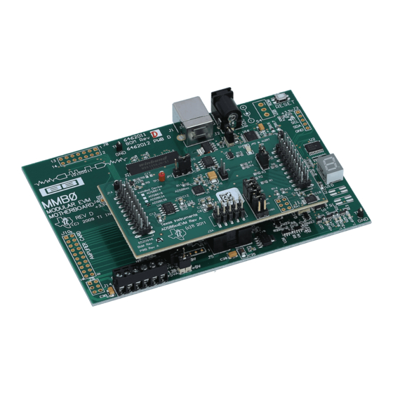
The MMB0 is a Modular EVM System motherboard. It is designed around the TMS320VC5507, a DSP with an onboard USB interface from Texas Instruments. The MMB0 also has 16 MB of SDRAM installed. The MMB0 is not sold as a DSP development board, and it is not available separately. TI cannot offer support for the MMB0 except as part of an EVM kit. -
Page 11: Laboratory Power-Supply Connections
Connecting the Power Supply The ADS8638EVM-PDK requires multiple supplies to power the ADC to be used with the MMB0 motherboard. The ADS8638 requires two high-voltage supplies (±10 V to ±15 V), HVDD and HVEE, along with a +5-V supply to power the analog, AVDD, and +3.3 V to +5 V to power the digital circuitry, DVDD. -
Page 12: Ni-Visa Driver Installation
The program for evaluating the ADS8638EVM-PDK is called ADCPro. This program uses plug-ins to communicate with the EVM. The ADS8638EVM-PDK plug-in is included in the ADS8638EVM-PDK package. -
Page 13: Ads86Xxevm-Pdk Plug-In
The status area displays Connected to EVM when the device is connected and ready to use. If the firmware does not load properly, you can try resetting the MMB0 by pressing Reset and then reloading the plug-in. SBAU192 – July 2011 ADS8638EVM-PDK Submit Documentation Feedback Copyright © 2011, Texas Instruments Incorporated... -
Page 14: Evaluating Performance With The Adcpro Software
Using the ADS8638EVM-PDK Plug-in The ADS8638EVM-PDK plug-in for ADCPro provides complete control over all settings of the ADS8638. It consists of a tabbed interface, with different functions available on different tabs. These controls are described in this section. -
Page 15: Device Configuration
ADC. Basic information, such as the Plug-in version and Firmware version, is shown here along with some simple settings use to set up the ADC according to user preferences. SBAU192 – July 2011 ADS8638EVM-PDK Submit Documentation Feedback Copyright © 2011, Texas Instruments Incorporated... - Page 16 The data rate displayed in the top right corner of the plugin refers to all enabled channels to be converted. SBAU192 – July 2011 ADS8638EVM-PDK Submit Documentation Feedback Copyright © 2011, Texas Instruments Incorporated...
-
Page 17: Channels Tabs
Evaluating Performance with the ADCPro Software www.ti.com Figure 10. Channels Tabs SBAU192 – July 2011 ADS8638EVM-PDK Submit Documentation Feedback Copyright © 2011, Texas Instruments Incorporated... -
Page 18: Gpios & Alarms Tab
ADS8638 product data sheet. The high and low alarms, along with hysteresis settings, behave the same way that the analog input channel alarm settings do. SBAU192 – July 2011 ADS8638EVM-PDK Submit Documentation Feedback Copyright © 2011, Texas Instruments Incorporated... - Page 19 Once you have configured the ADS8638 for your test scenario, press the ADCPro Acquire button to start the collection of the number of data points specified in the Test plug-in Block Size control. The ADS8638EVM-PDK plug-in disables all the front panel controls while acquiring, and displays a progress bar.
-
Page 20: Evm Bill Of Materials, Schematic, And Layout
TP1, TP2 Test point: single .025-Pin, Black Keystone 5001 Test point: single .025-Pin, Red Keystone 5000 ADS8638, 8-channel 12-bit HV MUX SAR ADC Texas ADS8638SRGER Instruments SBAU192 – July 2011 ADS8638EVM-PDK Submit Documentation Feedback Copyright © 2011, Texas Instruments Incorporated... -
Page 21: Ads8638Evm Pcb: Top Layer
NOTE: Board layouts are not to scale. These images are intended to show how the board is laid out; they are not intended to be used for manufacturing ADS8638EVM PCBs. Figure 12. ADS8638EVM PCB: Top Layer SBAU192 – July 2011 ADS8638EVM-PDK Submit Documentation Feedback Copyright © 2011, Texas Instruments Incorporated... -
Page 22: Ads8638Evm Pcb: Mid Layer
EVM Bill of Materials, Schematic, and Layout www.ti.com Figure 13. ADS8638EVM PCB: Mid Layer Figure 14. ADS8638EVM PCB: Ground Layer SBAU192 – July 2011 ADS8638EVM-PDK Submit Documentation Feedback Copyright © 2011, Texas Instruments Incorporated... -
Page 23: Ads8638Evm Pcb: Bottom Layer
EVM Bill of Materials, Schematic, and Layout www.ti.com Figure 15. ADS8638EVM PCB: Bottom Layer SBAU192 – July 2011 ADS8638EVM-PDK Submit Documentation Feedback Copyright © 2011, Texas Instruments Incorporated... - Page 24 HVEE HVDD 10uF +VBD +3.3VD 1uF (50V rated) 10uF 10uF 0.1uF OPA140 SN74LVC1G17 10uF +3.3VD AGND REF+ AGND REF- AIN0/NC VCOM AGND AIN1/NC SCLK AGND AGND AIN2/AIN0 A3(-) A3(+) A2(-) A2(+) AIN3/AIN1 A1(-) A1(+) A0(-) A0(+) AIN4/AIN2 GPIO DAUGHTER-ANALOG CNTL GPIO0 ADS86xx AIN5/AIN3...
- Page 25 Evaluation Board/Kit Important Notice Texas Instruments (TI) provides the enclosed product(s) under the following conditions: This evaluation board/kit is intended for use for ENGINEERING DEVELOPMENT, DEMONSTRATION, OR EVALUATION PURPOSES ONLY and is not considered by TI to be a finished end-product fit for general consumer use. Persons handling the product(s) must have electronics training and observe good engineering practice standards.
- Page 26 IMPORTANT NOTICE Texas Instruments Incorporated and its subsidiaries (TI) reserve the right to make corrections, modifications, enhancements, improvements, and other changes to its products and services at any time and to discontinue any product or service without notice. Customers should obtain the latest relevant information before placing orders and should verify that such information is current and complete.
Need help?
Do you have a question about the ADS8638EVM-PDK and is the answer not in the manual?
Questions and answers