
Related Manuals for Dell 7CX5T


Summary of Contents for Dell 7CX5T
- Page 1 Dell EMC PowerEdge T640 Installation and Service Manual Regulatory Model: E47S Series Regulatory Type: E47S001 July 2020 Rev. A12...
- Page 2 A WARNING indicates a potential for property damage, personal injury, or death. © 2017 - 2020 Dell Inc. or its subsidiaries. All rights reserved. Dell, EMC, and other trademarks are trademarks of Dell Inc. or its subsidiaries. Other trademarks may be trademarks of their respective owners.
-
Page 3: Table Of Contents
Contents Chapter 1: Dell EMC PowerEdge T640 overview.................8 Supported configurations..............................9 Front view of the system..............................10 Status LED indicators..............................12 iDRAC Direct LED indicator codes..........................13 iDRAC Quick Sync 2 indicator codes........................... 13 System health and system ID indicator codes......................14 Drive indicator codes.............................. - Page 4 System Setup..................................41 Viewing System Setup..............................41 System Setup details..............................42 System BIOS.................................. 42 iDRAC Settings utility..............................62 Device Settings................................63 Dell Lifecycle Controller..............................63 Embedded system management..........................63 Boot Manager..................................63 Viewing Boot Manager..............................63 Boot Manager main menu............................63 One-shot UEFI boot menu............................64 System Utilities................................
- Page 5 Installing a 3.5 inch drive adapter into the 3.5 inch drive carrier................78 Removing a 2.5 inch drive from a 3.5 inch drive adapter..................79 Installing a 2.5 inch drive into a 3.5 inch drive adapter.....................80 Power supply units................................81 PSU specifications................................. 81 Hot spare feature................................
- Page 6 Mode-specific guidelines..............................112 Removing a memory module............................114 Installing a memory module............................115 Processors and heat sinks..............................116 Removing a processor and heat sink module......................116 Removing the processor from the processor and heat sink module..............118 Installing the processor into a processor and heat sink module................119 Installing a processor and heat sink module......................
- Page 7 Chapter 6: System diagnostics..................... 162 Dell Embedded System Diagnostics..........................162 Running the Embedded System Diagnostics from Boot Manager................ 162 Running the Embedded System Diagnostics from the Dell Lifecycle Controller..........162 System diagnostic controls............................163 Chapter 7: Getting help........................ 164 Contacting Dell EMC................................. 164 Documentation feedback..............................164...
-
Page 8: Chapter 1: Dell Emc Poweredge T640 Overview
Dell EMC PowerEdge T640 overview The Dell EMC PowerEdge T640 is a dual-socket, 5U rackable tower server that supports up to: • Two Intel Xeon Scalable processors • 24 DIMM slots (support for DDR4 RDIMM, LR-DIMM) or 12 NVDIMM-N (one DIMM per channel) are supported •... -
Page 9: Supported Configurations
Supported configurations Figure 1. Supported configurations of the PowerEdge T640 Dell EMC PowerEdge T640 overview... -
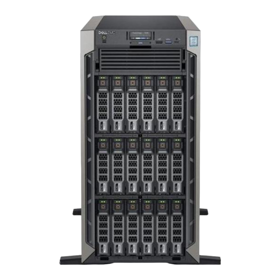
Page 10: Front View Of The System
3. iDRAC Quick Sync 2 wireless indicator (optional) 4. Status LED indicators 5. System health and system ID indicator 6. USB port (USB 2.0-compliant) 7. USB port (USB 3.0-compliant) 8. iDRAC Direct (Micro-AB USB) port 9. Optical drive (optional) 10. Drive slots Dell EMC PowerEdge T640 overview... - Page 11 3. iDRAC Quick Sync 2 wireless indicator (optional) 4. Status LED indicators 5. System health and system ID indicator 6. USB port (USB 2.0-compliant) 7. USB port (USB 3.0-compliant) 8. iDRAC Direct (Micro-AB USB) port 9. Optical drive (optional) 10. Drive slots Dell EMC PowerEdge T640 overview...
-
Page 12: Status Led Indicators
For more information about the supported PCIe cards, see Expansion card installation guidelines. Memory The indicator turns Check the System Event Log or system messages for the location of the indicator solid amber if a failed memory. Reseat the memory module. Dell EMC PowerEdge T640 overview... -
Page 13: Idrac Direct Led Indicator Codes
Indicates that the laptop or tablet is unplugged. iDRAC Quick Sync 2 indicator codes iDRAC Quick Sync 2 module (optional) is located on the front panel of your system. Figure 6. iDRAC Quick Sync 2 indicator Dell EMC PowerEdge T640 overview... -
Page 14: System Health And System Id Indicator Codes
Event Log for specific error messages. For information about the event and error messages generated by the system firmware and agents that monitor system components, go to qrl.dell.com > Look Up > Error Code, type the error code, and then click Look it up.. Dell EMC PowerEdge T640 overview... -
Page 15: Drive Indicator Codes
Flashes amber four times per second Drive failed. Flashes green slowly Drive rebuilding. Solid green Drive online. Flashes green for three seconds, amber for three seconds, Rebuild stopped. and then turns off after six seconds Dell EMC PowerEdge T640 overview... -
Page 16: Back View Of The System
4. Serial port 5. iDRAC9 dedicated network port 6. USB 2.0 port (2) 7. PCIe expansion card slots 8. NIC port (2) 9. System Identification connector 10. USB 3.0 port (4) 11. Power supply unit (2) Dell EMC PowerEdge T640 overview... -
Page 17: Nic Indicator Codes
NIC, and the link LED indicator indicates the speed of the connected network. Figure 11. NIC indicator codes 1. link LED indicator 2. activity LED indicator Table 6. NIC indicator codes Status Condition Link and activity indicators are off The NIC is not connected to the network. Dell EMC PowerEdge T640 overview... -
Page 18: Power Supply Unit Indicator Codes
Swapping the PSU to make a matched pair can result in an error condition and unexpected system shutdown. To change from a high output configuration to a low output configuration or vice versa, you must turn off the system. Dell EMC PowerEdge T640 overview... - Page 19 Output configuration or vice versa, you must turn off the system. CAUTION: If two PSUs are used, they must be of the same type and have the same maximum output power. CAUTION: Combining AC and DC PSUs is not supported and triggers a mismatch. Dell EMC PowerEdge T640 overview...
-
Page 20: Locating The Service Tag Of Your System
Express Service Code and Service Tag. Alternatively, the information may be on a sticker on the chassis of the system. The mini Enterprise Service Tag (EST) is found on the back of the system. This information is used by Dell to route support calls to the appropriate personnel. - Page 21 Figure 16. Configuration and layout Dell EMC PowerEdge T640 overview...
- Page 22 Figure 17. Electrical overview Dell EMC PowerEdge T640 overview...
- Page 23 Figure 18. Memory information Dell EMC PowerEdge T640 overview...
- Page 24 Figure 19. System tasks Dell EMC PowerEdge T640 overview...
-
Page 25: Chapter 2: Technical Specifications
System battery specifications • Expansion bus specifications • Memory specifications • Storage controller specifications • Drive specifications • Ports and connectors specifications • Video specifications • Environmental specifications Chassis dimensions Figure 20. Dimensions of the Dell EMC PowerEdge T640 system Technical specifications... -
Page 26: Chassis Weight
18 x 3.5-inch 49.65 Kg (109.45 lb) Processor specifications The Dell EMC PowerEdge T640 system supports up to two Intel Xeon Scalable processors, up to 28 cores per processor. Supported operating systems The PowerEdge T640 system supports the following operating systems: •... -
Page 27: Cooling Fan Matrix
• Solarflare Sunspot DP 10Gb NIC (NPHCM) • Solarflare Nova DP 10Gb NIC (WY7T5) • Qlogic DP 10Gb V1 NIC (VCXN5) Listed below are the restrictions for fan redundancy: • GPGPU configurations are not supported at 35deg. C of ambient or above. •... -
Page 28: Installing A Middle Or Rear Cooling Fan
Figure 21. Removing a middle cooling fan Next steps Installing a middle or rear cooling fan. Installing a middle or rear cooling fan The procedure for installing a standard and a high performance fans is identical. Prerequisites NOTE: Opening or removing the system cover when the system is on may expose you to a risk of electric shock. Exercise utmost care while removing or installing cooling fans. -
Page 29: Removing The Right External Fan
Figure 22. Installing a middle cooling fan Next steps 1. Follow the procedure listed in After working inside your system on page 66. Removing the right external fan Prerequisites NOTE: Opening or removing the system cover when the system is on may expose you to a risk of electric shock. Exercise utmost care while removing or installing cooling fans. -
Page 30: Installing The Right External Fan
Figure 23. Removing the right external fan Next steps Installing the right external fan. Installing the right external fan Prerequisites NOTE: The procedure to install the left external fan is similar to installing the right rear fan. Follow the safety guidelines listed in Safety instructions on page 65. -
Page 31: Psu Specifications
The Dell EMC PowerEdge T640 system supports CR 2032 3.0-V lithium coin cell system battery. Expansion bus specifications The Dell EMC PowerEdge T640 system supports PCI express (PCIe) generation 3 and 2 expansion cards. The following table describes the supported expansion cards:... -
Page 32: Memory Specifications
8 GB RDIMMs and NVDIMM-N must not be mixed. NOTE: A minimum of two processors are required for any configuration that supports NVDIMM-N DIMMs. Storage controller specifications The Dell EMC PowerEdge T640 system supports: • Internal controllers: PERC H730P, H740P, HBA330, H330, Software RAID (SWRAID) S140 •... -
Page 33: Drive Specifications
The LOM (Broadcom 57416) is compatible with 10GBASE-T IEEE 802.3an and 1000 BASE-T IEEE 802.3ab. VGA ports The Video Graphic Array (VGA) port enables you to connect the system to a VGA display. The Dell EMC PowerEdge T640 system supports two 15-pin VGA ports on the front and back panels. -
Page 34: Serial Connector
Serial connector The Dell EMC PowerEdge T640 system supports one serial connector on the back panel, which is a 9-pin connector, Data Terminal Equipment (DTE), 16550-compliant. Internal Dual SD Module with vFlash card The Dell EMC PowerEdge T640 system supports Internal Dual SD module (IDSDM) and vFlash card. In 14th generation of PowerEdge servers, IDSDM and vFlash card are combined into a single card module, and are available in anyone of these configurations: •... -
Page 35: Standard Operating Temperature
Table 17. Temperature specifications (continued) Temperature Specifications Fresh air For information about fresh air, see Expanded Operating Temperature section. Maximum temperature gradient (operating and storage) 20°C/h (68°F/h) Table 18. Relative humidity specifications Relative humidity Specifications Storage 5% to 95% RH with 33°C (91°F) maximum dew point. Atmosphere must be non-condensing at all times. -
Page 36: Expanded Operating Temperature
Processor > 165 W is not supported. • Internal TBU (tape backup drive) is not supported. • Non-Dell qualified peripheral cards are not supported. • Peripheral cards consuming greater than 25 W are not supported. • 128 GB LRDIMM is supported. - Page 37 Table 25. Particulate contamination specifications (continued) Particulate contamination Specifications NOTE: Air entering the data center must have MERV11 or MERV13 filtration. Conductive dust Air must be free of conductive dust, zinc whiskers, or other conductive particles. NOTE: This condition applies to data center and non-data center environments.
-
Page 38: Chapter 3: Initial System Setup And Configuration
For more information about setting up your system, see the Getting Started Guide that shipped with your system. iDRAC configuration The Integrated Dell Remote Access Controller (iDRAC) is designed to make system administrators more productive and improve the overall availability of Dell systems. iDRAC alerts administrators about system issues and enables them to perform remote system management. -
Page 39: Log In To Idrac
Ensure that you change the default username and password after setting up the iDRAC IP address. For more information about logging in to the iDRAC and iDRAC licenses, see the latest Integrated Dell Remote Access Controller User's Guide at www.dell.com/poweredgemanuals. -
Page 40: Downloading Drivers And Firmware
Using iDRAC virtual media www.dell.com/idracmanuals Downloading drivers and firmware Dell EMC recommends that you download and install the latest BIOS, drivers, and systems management firmware on your system. Prerequisites Ensure that you clear the web browser cache before downloading the drivers and firmware. -
Page 41: Chapter 4: Pre-Operating System Management Applications
You can manage basic settings and features of a system without booting to the operating system by using the system firmware. Topics: • Options to manage the pre-operating system applications • System Setup • Dell Lifecycle Controller • Boot Manager • PXE boot Options to manage the pre-operating system applications Your system has the following options to manage the pre-operating system applications: •... -
Page 42: System Setup Details
The iDRAC settings utility is an interface to set up and configure the iDRAC parameters by using UEFI (Unified Extensible Firmware Interface). You can enable or disable various iDRAC parameters by using the iDRAC settings utility. For more information about this utility, see Integrated Dell Remote Access Controller User’s Guide at www.dell.com/poweredgemanuals. - Page 43 Option Description Integrated Devices Provides options to manage integrated device controllers and ports, specifies related features and options. Serial Provides options to manage the serial ports, their related features and options. Communication System Profile Provides options to change the processor power management settings, and memory frequency. Settings System Security Provides options to configure the system security settings, such as system password, setup password, Trusted...
- Page 44 Memory Operating Specifies the memory operating mode. The options available are Optimizer Mode, Single Rank Spare Mode, Mode Multi Rank Spare Mode, Mirror Mode, and Dell Fault Resilient Mode. This option is set to Optimizer Mode by default. NOTE: The Memory Operating Mode option can have different default and available options based on the memory configuration of your system.
- Page 45 Description NOTE: The Dell Fault Resilient Mode option establishes an area of memory that is fault resilient. This mode can be used by an operating system that supports the feature to load critical applications or enables the operating system kernel to maximize system availability.
- Page 46 Processor Settings details About this task The Processor Settings screen details are explained as follows: Option Description Logical Processor Enables or disables the logical processors and displays the number of logical processors. If this option is set to Enabled, the BIOS displays all the logical processors. If this option is set to Disabled, the BIOS displays only one logical processor per core.
- Page 47 Option Description Intel SST-CP Enable Intel SST-CP. This option is displayed if Performance Per Watt (operating system) or Custom (when OSPM is enabled) system profiles are selected. It is set to Disabled by default. Configurable TDP Enables you to configure the TDP level. The available options are Nominal, Level 1, and Level 2. This option is set to Nominal by default.
- Page 48 SATA Settings details About this task The SATA Settings screen details are explained as follows: Option Description Embedded SATA Enables the embedded SATA option to be set to Off, or AHCI Mode, or RAID Mode. This option is set to AHCI Mode by default.
- Page 49 Boot Settings You can use the Boot Settings screen to set the boot mode to either BIOS or UEFI. It also enables you to specify the boot order. • UEFI: The Unified Extensible Firmware Interface (UEFI) is a new interface between operating systems and platform firmware. The interface consists of data tables with platform related information, boot and runtime service calls that are available to the operating system and its loader.
- Page 50 Operating systems must be UEFI-compatible to be installed from the UEFI boot mode. DOS and 32-bit operating systems do not support UEFI and can only be installed from the BIOS boot mode. NOTE: For the latest information about supported operating systems, go to www.dell.com/ossupport. Changing boot order About this task You may have to change the boot order if you want to boot from a USB key.
- Page 51 Viewing Network Settings To view the Network Settings screen, perform the following steps: Steps 1. Power on, or restart your system. 2. Press F2 immediately after you see the following message: F2 = System Setup NOTE: If your operating system begins to load before you press F2, wait for the system to finish booting, and then restart your system and try again.
- Page 52 Integrated Devices You can use the Integrated Devices screen to view and configure the settings of all integrated devices including the video controller, integrated RAID controller, and the USB ports. Viewing Integrated Devices To view the Integrated Devices screen, perform the following steps: Steps 1.
- Page 53 Option Description NOTE: When there are multiple add-in graphic cards installed in the system, the first card discovered during PCI enumeration is selected as the primary video. You might have to re-arrange the cards in the slots in order to control which card is the primary video. Current State of Displays the current state of the embedded video controller.
- Page 54 Serial Communication You can use the Serial Communication screen to view the properties of the serial communication port. Viewing Serial Communication To view the Serial Communication screen, perform the following steps: Steps 1. Power on, or restart your system. 2. Press F2 immediately after you see the following message: F2 = System Setup NOTE: If your operating system begins to load before you press F2, wait for the system to finish booting, and then...
- Page 55 You can only change the rest of the options if the mode is set to Custom.This option is set to Performance Per Watt Optimized (DAPC) by default. DAPC is Dell Active Power Controller.
- Page 56 Option Description Number of Turbo NOTE: If there are two processors installed in the system, you will see an entry for Number of Boost Enabled Turbo Boost Enabled Cores for Processor 2. Cores for Controls the number of turbo boost enabled cores for Processor 1. The maximum number of cores is All by Processor 1 default.
- Page 57 Option Description System Password Enables you to set the system password. This option is set to Enabled by default and is read-only if the password jumper is not installed in the system. Setup Password Enables you to set the system setup password. This option is read-only if the password jumper is not installed in the system.
- Page 58 Option Description This field is read-only when TPM Security is set to Off. The action requires an additional reboot before it can take effect. TPM Advanced This setting is enabled only when TPM Security is set to ON. Settings Table 33. TPM Advanced Settings Details Option Description TPM PPI Bypass Provision...
- Page 59 Option Description Options Description Audit Mode In Audit mode, PK is not present. BIOS does not authenticate programmatic updates to the policy objects, and transitions between modes. Audit Mode is useful for programmatically determining a working set of policy objects. BIOS performs signature verification on pre-boot images.
- Page 60 Using your system password to secure the system About this task If you have assigned a setup password, the system accepts your setup password as an alternate system password. Steps 1. Power on or reboot your system. 2. Type the system password and press Enter. Next steps When Password Status is set to Locked, type the system password and press Enter when prompted at reboot.
- Page 61 NOTE: You can use the password status option with the setup password option to protect the system password from unauthorized changes. Redundant OS Control In the Redundant OS Control screen you can set the redundant OS information. This enables you to set up a physical recovery disk on the system.
-
Page 62: Idrac Settings Utility
UEFI boot mode. You cannot set the option to Enabled if UEFI Secure Boot mode is enabled. This option is set to Disabled by default. Dell Wyse Enables or disables the Dell Wyse P25/P45 BIOS Access. This option is set to Enabled by default. P25/P45 BIOS Access Power Cycle Enables or disables the Power Cycle Request. -
Page 63: Device Settings
Dell Lifecycle Controller Dell Lifecycle Controller (LC) provides advanced embedded systems management capabilities including system deployment, configuration, update, maintenance, and diagnosis. LC is delivered as part of the iDRAC out-of-band solution and Dell system embedded Unified Extensible Firmware Interface (UEFI) applications. -
Page 64: One-Shot Uefi Boot Menu
Menu item Description System Utilities Enables you to launch System Utilities menu such as System Diagnostics and UEFI shell. One-shot UEFI boot menu One-shot UEFI boot menu enables you to select a boot device to boot from. System Utilities System Utilities contains the following utilities that can be launched: •... -
Page 65: Chapter 5: Installing And Removing System Components
Installing and removing system components The following sections contain the procedures for removing and replacing system components. Topics: • Safety instructions • Before working inside your system • After working inside your system • Optional front bezel • System feet •... -
Page 66: Before Working Inside Your System
Damage due to servicing that is not authorized by Dell is not covered by your warranty. Read and follow the safety instructions that are shipped with your product. -
Page 67: Installing The Front Bezel
Figure 25. Removing the front bezel Next steps Installing the front bezel. Installing the front bezel Prerequisites Follow the safety guidelines listed in Safety instructions on page 65. Steps 1. Locate and remove the bezel key. NOTE: There are two bezel keys attached to the back of the bezel. 2. -
Page 68: System Feet
Figure 26. Installing the front bezel System feet Removing the system feet Prerequisites NOTE: It is recommended that you remove the system feet only when you are converting the system from the tower mode to the rack mode, or when you are replacing the system feet with the wheel assembly. 1. -
Page 69: Installing The System Feet
Figure 27. Removing the system feet Next steps Install the system feet install the castor wheels. Installing the system feet Prerequisites CAUTION: Install the feet on a stand-alone tower system to provide stability to the system. An unstable system might tip over and cause injury to the user or damage to the system. -
Page 70: Caster Wheels - Optional
Figure 28. Installing the system feet Next steps 1. Place the system upright on a flat, stable surface, and rotate the system feet outward. 2. Follow the procedure listed in After working inside your system on page 66. Caster wheels – optional Removing caster wheels Prerequisites 1. -
Page 71: Installing Caster Wheels
Figure 29. Removing caster wheels Next steps Install the caster wheels the system feet, as applicable. Installing caster wheels Prerequisites 1. Follow the safety guidelines listed in Safety instructions on page 65. 2. Place the system on its side on a flat, stable surface. 3. -
Page 72: Drives
Figure 30. Installing caster wheels Next steps 1. Follow the procedure listed in Before working inside your system on page 66. Drives Removing a drive blank The procedure for removing 2.5 inch and 3.5 inch drive blanks is identical. Prerequisites 1. -
Page 73: Installing A Drive Blank
Figure 31. Removing a drive blank Next steps Install a drive drive blank. Installing a drive blank The procedure for installing 2.5 inch and 3.5 inch drive blanks is identical. Prerequisites 1. Follow the safety guidelines listed in Safety instructions on page 65. -
Page 74: Removing A Drive Carrier
Removing a drive carrier Prerequisites 1. Follow the safety guidelines listed in Safety instructions on page 65. 2. If applicable, remove the front bezel 3. Using the management software, prepare the drive for removal. If the drive is online, the green activity or fault indicator flashes while the drive is turning off. When the drive indicators are off, the drive is ready for removal. -
Page 75: Removing The Drive From The Drive Carrier
CAUTION: Combining SAS and SATA drives in the same RAID volume is not supported. CAUTION: When installing a drive, ensure that the adjacent drives are fully installed. Inserting a drive carrier and attempting to lock its handle next to a partially installed carrier can damage the partially installed carrier's shield spring and make it unusable. -
Page 76: Installing A Drive Into The Drive Carrier
Figure 35. Removing the drive from the drive carrier Next steps Installing the drive into the drive carrier. Installing a drive into the drive carrier Prerequisites Follow the safety guidelines listed in Safety instructions on page 65. CAUTION: Mixing drive carriers from other generations of PowerEdge servers is not supported. NOTE: When installing a drive into the drive carrier, ensure that the screws are torqued to 4 in-lbs. -
Page 77: Removing A 3.5 Inch Drive Adapter From A 3.5 Inch Drive Carrier
Figure 36. Installing a drive into the drive carrier Removing a 3.5 inch drive adapter from a 3.5 inch drive carrier Prerequisites 1. Follow the safety guidelines listed in Safety instructions on page 65. 2. If installed, remove the front bezel. Remove the drive carrier. -
Page 78: Installing A 3.5 Inch Drive Adapter Into The 3.5 Inch Drive Carrier
Figure 37. Removing a 3.5 inch drive adapter from a 3.5 inch drive carrier Next steps Install the 3.5 inch drive adapter into the 3.5 inch drive carrier Installing a 3.5 inch drive adapter into the 3.5 inch drive carrier Prerequisites 1. -
Page 79: Removing A 2.5 Inch Drive From A 3.5 Inch Drive Adapter
Figure 38. Installing a 3.5 inch drive adapter into the 3.5 inch drive carrier Next steps Install the drive carrier. 2. If removed, install the front bezel. Removing a 2.5 inch drive from a 3.5 inch drive adapter Prerequisites 1. Follow the safety guidelines listed in Safety instructions on page 65. -
Page 80: Installing A 2.5 Inch Drive Into A 3.5 Inch Drive Adapter
Figure 39. Removing a 2.5 inch drive from a 3.5 inch drive adapter Next steps Install a 2.5 inch drive into a 3.5 inch drive adapter. Installing a 2.5 inch drive into a 3.5 inch drive adapter Prerequisites 1. Follow the safety guidelines listed in Safety instructions on page 65. -
Page 81: Power Supply Units
Figure 40. Installing a 2.5 inch drive into a 3.5 inch drive adapter Next steps Install the 3.5 inch drive adapter into the 3.5 inch hot swappable drive carrier. Power supply units PSU specifications The power supply unit (PSU) is an internal hardware component which supplies power to the components in the system. Your system supports one of the following: •... -
Page 82: Hot Spare Feature
If the load on the active PSU falls below 20 percent of PSU rated power wattage, then the redundant PSU is switched to the sleep state. You can configure the hot spare feature by using the iDRAC settings. For more information, see the iDRAC User’s Guide available at Dell.com/idracmanuals. Removing a power supply unit blank Prerequisites... -
Page 83: Removing A Ac Power Supply Unit
Steps Align the PSU blank with the PSU slot and push it into the PSU slot until it clicks into place. Figure 42. Installing a power supply unit blank Next steps 1. Follow the procedure listed in After working inside your system on page 66. -
Page 84: Installing A Ac Power Supply Unit
All electrical wiring must comply with applicable local or national codes and practices. Damage due to servicing that is not authorized by Dell is not covered by your warranty. Read and follow all safety instructions that came with the product. -
Page 85: Installing Dc Power Supply Unit
All electrical wiring must comply with applicable local or national codes and practices. Damage due to servicing that is not authorized by Dell is not covered by your warranty. Read and follow all safety instructions that came with the product. -
Page 86: System Cover
• Current consumption: 32 A (maximum) Kit contents • Dell part number 6RYJ9 terminal block or equivalent (1) • #6-32 nut equipped with lock washer (1) Required tools Wire-stripper pliers capable of removing insulation from size 10 AWG solid or stranded, insulated copper wire. -
Page 87: Installing The System Cover
Figure 45. Removing the system cover Next steps Install the system cover. Installing the system cover Prerequisites NOTE: Ensure that all internal cables are connected and placed out of the way and no tools or extra parts are left inside the system. -
Page 88: Inside The System
Figure 46. Installing the system cover Next steps 1. Place the system upright on its feet on a flat and stable surface. 2. If removed, install the front bezel. 3. Reconnect the peripherals and connect the system to the electrical outlet. 4. - Page 89 5. Internal PERC 6. PCIe card holder 7. PCIe slots 8. Left external fan 9. Right external fan 10. CPU2 socket 11. CPU1 12. Backplane Installing and removing system components...
-
Page 90: Air Shroud
Air shroud Removing the optional GPU air shrouds Prerequisites CAUTION: Never operate your system with the air shroud removed. The system may get overheated quickly, resulting in shutdown of the system and loss of data. 1. Follow the safety guidelines listed in Safety instructions on page 65. -
Page 91: Removing The Air Shroud
2. Lower the GPU air shroud into the chassis until it is firmly seated. Figure 48. Installing the optional GPU air shrouds Next steps Follow the procedure listed in After working inside your system on page 66. Removing the air shroud Prerequisites CAUTION: Never operate your system with the air shroud removed. -
Page 92: Installing The Air Shroud
Figure 49. Removing the air shroud Next steps Install the air shroud. Installing the air shroud Prerequisites 1. Follow the safety guidelines listed in Safety instructions on page 65. 2. If applicable, route the cables inside the system along the chassis wall and secure the cables by using the cable-securing bracket. Steps 1. -
Page 93: Cooling Fans
Figure 50. Installing the air shroud Next steps 1. Follow the procedure listed in After working inside your system on page 66. Cooling fans Cooling fan specifications The cooling fans are integrated into the system to dissipate the heat generated by the functioning of the system. These fans provide cooling for the processors, expansion cards, and memory modules. -
Page 94: Cooling Fan Matrix
• GPGPU configurations are not supported at 35deg. C of ambient or above. • Mellanox 100G NICs are not supported. For information on the restriction for fresh air condition, see the Expanded operating temperature restrictions topic in the Technical Specification section. Cooling fan matrix Table 34. -
Page 95: Installing A Middle Or Rear Cooling Fan
Figure 51. Removing a middle cooling fan Next steps Installing a middle or rear cooling fan. Installing a middle or rear cooling fan The procedure for installing a standard and a high performance fans is identical. Prerequisites NOTE: Opening or removing the system cover when the system is on may expose you to a risk of electric shock. Exercise utmost care while removing or installing cooling fans. -
Page 96: Removing The Right External Fan
Figure 52. Installing a middle cooling fan Next steps 1. Follow the procedure listed in After working inside your system on page 66. Removing the right external fan Prerequisites NOTE: Opening or removing the system cover when the system is on may expose you to a risk of electric shock. Exercise utmost care while removing or installing cooling fans. -
Page 97: Installing The Right External Fan
Figure 53. Removing the right external fan Next steps Installing the right external fan. Installing the right external fan Prerequisites NOTE: The procedure to install the left external fan is similar to installing the right rear fan. Follow the safety guidelines listed in Safety instructions on page 65. -
Page 98: Cooling Fan (Middle Fan) Assembly
Cooling fan (middle fan) assembly Removing the middle cooling fan assembly Prerequisites 1. Follow the safety guidelines listed in Safety instructions on page 65. 2. Follow the procedure listed in Before working inside your system on page 66. Steps 1. Lift the release levers to unlock the cooling fan assembly from the system. 2. -
Page 99: Flex Bays
2. Lower the cooling fan assembly into the system until the cooling fan connectors engage with the connectors on the system board. 3. Press the release levers to lock the cooling fan assembly into the system. Figure 56. Installing the middle cooling fan assembly Next steps 1. -
Page 100: Installing A Nvme Drive Bay Or Flex Bay
Figure 57. Removing a NVMe drive bay or flex bay Next steps Installing the NVMe drive bay or flex bay. Installing a NVMe drive bay or flex bay Prerequisites NOTE: The procedure to install the flex bay is identical to installing the NVMe drive bay. Follow the safety guidelines listed in Safety instructions on page 65. -
Page 101: Optical Drives And Tape Drives
Figure 58. Installing a NVMe drive bay or flex bay Next steps Install the backplane to the NVMe drive bay or flex bay. 2. Connect the slim optical drive and the back plane cables. 3. Follow the procedure listed in After working inside your system on page 66. -
Page 102: Installing The Optical Or Tape Drive Blank
Steps 1. To remove the drive blank, slide the release latch down to release the drive blank. 2. Push the drive blank to slide it out of the drive bay. NOTE: Blanks must be installed on empty optical drive or tape drive slots to maintain FCC certification of the system. -
Page 103: Removing The Optical Drive Cage Or Tape Drive
Figure 60. Installing the optical or tape drive blank Next steps 1. If removed, install the front bezel. 2. Follow the procedure listed in After working inside your system on page 66. Removing the optical drive cage or tape drive Prerequisites NOTE: The procedure to remove the optical drive cage is identical to removing a tape drive. -
Page 104: Installing The Optical Drive Cage Or Tape Drive
Figure 61. Removing the optical drive cage or tape drive Next steps Install the optical drive cage or tape drive. Installing the optical drive cage or tape drive Prerequisites NOTE: The procedure to install the optical drive cage is the same as installing the tape drive. Follow the safety guidelines listed in Safety instructions on page 65. -
Page 105: Removing The Slim Optical Drive
Figure 62. Installing the optical drive cage or tape drive Next steps 1. If removed, install the front bezel. 2. Follow the procedure listed in After working inside your system on page 66. Removing the slim optical drive The procedure to remove the slim optical drive blank is similar to removing the slim optical drive. Prerequisites 1. -
Page 106: Installing The Slim Optical Drive
Figure 63. Removing the slim optical drive blank Next steps Install the slim optical drive or the optical drive blank. Installing the slim optical drive The procedure to install the optical drive blank is similar to installing the slim optical drive. Prerequisites Follow the safety guidelines listed in Safety instructions... -
Page 107: Nvdimm-N Battery
Next steps Install the optical drive cage. 2. Follow the procedure listed in After working inside your system on page 66. NVDIMM-N battery Removing the NVDIMM-N battery Prerequisites 1. Follow the safety guidelines listed in Safety instructions on page 65. 2. -
Page 108: Installing The Nvdimm-N Battery
Installing the NVDIMM-N battery Prerequisites CAUTION: To avoid damage to the battery connector, you must firmly support the connector while installing or removing a battery. Follow the safety guidelines listed in Safety instructions on page 65. Steps 1. Install the NVDIMM-N battery into the battery cage 2. - Page 109 Figure 67. System memory view Table 36. Memory channels Proce Channel 0 Channel 1 Channel 2 Channel 3 Channel 4 Channel 5 ssor Proces Slots A1 and A7 Slots A2 and A8 Slots A3 and A9 Slots A4 and A10 Slots A5 and A11 Slots A6 and A12 sor 1...
-
Page 110: General Memory Module Installation Guidelines
Table 37. Memory population (continued) DIMM Type DIMMs Populated/ Operating Frequency (in Maximum DIMM Rank/ Voltage Channel MT/s) Channel NVDIMM-N 1.2 V 2933, 2666, 2400, 2133 Single rank NVDIMM population rules • Maximum of one NVDIMM per channel. • Maximum of six NVDIMMs per processor •... -
Page 111: Nvdimm-N Memory Module Installation Guidelines
All slots on configurations 3, 6, 9, and 12 can be used, but a maximum of 12 NVDIMM-Ns can be installed in a system. For more information on the supported NVDIMM-N configurations, see the NVDIMM-N User Guide at www.dell.com/poweredgemanuals. Table 38. Supported NVDIMM-N for dual processor configurations... -
Page 112: Mode-Specific Guidelines
Table 38. Supported NVDIMM-N for dual processor configurations (continued) Configuration Description Memory population rules RDIMMs NVDIMM-N Configuration 10 12x 16 GB RDIMMs, 6x Same for all 12x RDIMM Processor1 {A7, 8, 9} NVDIMM-Ns configurations. See Processor2 {B7, 8, 9} Configuration 1. Configuration 11 12x 32 GB RDIMMs, 6x Same for all 12x RDIMM... - Page 113 Dell Fault Resilient Mode The Dell Fault Resilient Mode if enabled, the BIOS creates an area of memory that is fault resilient. This mode can be used by an OS that supports the feature to load critical applications or enables the OS kernel to maximize system availability.
-
Page 114: Removing A Memory Module
Table 40. Memory population rules (continued) Processor Configuration Memory population Memory population information • Requires three ranks or more per channel. Fault resilient population {1, 2, 3, 4, 5, 6} {7, 8, 9, 10, Supported with 6 or 12 DIMMs per processor. order 11, 12} Dual processor (Start... -
Page 115: Installing A Memory Module
WARNING: Allow the memory modules to cool after you power off the system. Handle the memory modules by the card edges and avoid touching the components or metallic contacts on the memory module. CAUTION: To ensure proper system cooling, memory module blanks must be installed in any memory socket that is not occupied. -
Page 116: Processors And Heat Sinks
2. Open the ejectors on the memory module socket outward to allow the memory module to be inserted into the socket. 3. Align the edge connector of the memory module with the alignment key of the memory module socket, and insert the memory module in the socket. - Page 117 Steps 1. Using a Torx #T30 screwdriver, loosen the screws on the heat sink in the order below: a. Loosen the first screw three turns. b. Loosen the second screw completely. c. Return to the first screw and loosen it completely. 2.
-
Page 118: Removing The Processor From The Processor And Heat Sink Module
Removing the processor from the processor and heat sink module Prerequisites NOTE: Only remove the processor from the processor and heat sink module if you are replacing the processor or heat sink. This procedure is not required when replacing a system board. 1. -
Page 119: Installing The Processor Into A Processor And Heat Sink Module
Figure 72. Removing the processor bracket Next steps Install the processor into the processor and heat sink module. Installing the processor into a processor and heat sink module Prerequisites Follow the safety guidelines listed in Safety instructions on page 65. Steps 1. - Page 120 Figure 73. Installing the processor bracket 3. If you are using an existing heat sink, remove the thermal grease from the heat sink by using a clean lint-free cloth. 4. Use the thermal grease syringe included with your processor kit to apply the grease in a quadrilateral design on the top of the processor.
-
Page 121: Installing A Processor And Heat Sink Module
• Do not press on the heat sink fins. • Ensure that the pin 1 indicator on the heat sink is aligned with the pin 1 indicator on the bracket before placing the heat sink onto the processor and bracket. Figure 75. - Page 122 Steps 1. Align the pin 1 indicator of the heat sink to the system board and then place the processor and heat sink module (PHM) on the processor socket. CAUTION: To avoid damaging the fins on the heat sink, do not press down on the heat sink fins. NOTE: Ensure that the PHM is held parallel to the system board to prevent damaging the components.
-
Page 123: Expansion Card Holder
Figure 76. Installing a processor and heat sink module Next steps 1. Follow the procedure listed in After working inside your system on page 66. Expansion card holder Removing the expansion card holder Prerequisites 1. Follow the safety guidelines listed in Safety instructions on page 65. -
Page 124: Installing The Expansion Card Holder
Figure 77. Removing the expansion card holder Next steps Install the expansion card holder. Installing the expansion card holder Prerequisites Follow the safety guidelines listed in Safety instructions on page 65. Steps Align the expansion card holder with the guide pins on the system and push it down until it locks in place. Figure 78. -
Page 125: Gpu Card Installation Guidelines
• Two external fans are required for GPU-ready SKUs, there is no SKU with left external fan only. • If a GPU is installed on slot 1 or 3, only one 5.25 inch RMSD device (ODD/RD1000/half-height tape) is supported. • Four single width GPUs cannot be supported if the second PERC with battery (H730/H730P/H830). -
Page 126: Installing The Optional Gpu Card Holder
Figure 79. Removing the GPU card holder Next steps Install the optional GPU card holder. Installing the optional GPU card holder Prerequisites Follow the safety guidelines listed in Safety instructions on page 65. Steps Align the GPU card holder with the slots and the guide pin on the system, and push the GPU card holder down until it locks in place. Installing and removing system components... -
Page 127: Expansion Cards
Figure 80. Installing the optional GPU card holder Next steps Install the air shroud. 2. Follow the procedure listed in After working inside your system on page 66. Expansion cards Expansion card installation guidelines The following table describes the supported expansion cards: Table 41. -
Page 128: Expansion Card Slot Priority
Card Card Type Slot Priority Maximum Priority Allowed 1 or 2 CPU, no GPU (no Dell PowerEdge Express Flash (PCIe SSD) Bridge 1, 3 external fan) RAID (H330), RAID (H730P) RAID (H740P) 0, 1 RAID (H840), BOSS 4, 7, 1, 6, 8... -
Page 129: Removing A Expansion Card
7, 8, 6, 4 HBA330 0, 1, 3 PCIe SSD 1, 3, 7, 8, 6, 4 2 CPU, 2 External fans Dell PowerEdge Express Flash (PCIe SSD) Bridge 1, 3 GPUs 3, 6, 8, 1 RAID (H330), RAID (H730) RAID (H740) -
Page 130: Installing An Expansion Card
4. Install the filler brackets by performing the following steps: a. Align the slot on the filler bracket with the tab on the expansion card slot. b. Press the expansion card latch till the filler bracket locks into place. NOTE: Filler brackets must be installed in empty expansion-card slots to maintain FCC certification of the system. - Page 131 For instructions, see the documentation accompanying the card. 2. Open the expansion card latch adjacent to the slot you want to install the expansion card. 3. Remove the existing expansion card or filler bracket from the expansion card holder. NOTE: Store this bracket for future use.
-
Page 132: M.2 Ssd Module
M.2 SSD module Removing the M.2 SSD module Prerequisites 1. Follow the safety guidelines listed in Safety instructions on page 65. 2. Follow the procedure listed in Before working inside your system on page 66. Remove the air shroud. 4. Remove the BOSS card. NOTE: Removing the BOSS card is similar to the procedure for removing an expansion card riser. -
Page 133: Optional Microsd Or Vflash Card
Figure 86. Installing the M.2 SSD module Next steps 1. Install the BOSS card. NOTE: Installing the BOSS card is similar to installing the expansion card riser. Install the air shroud. 3. Follow the procedure listed in After working inside your system on page 66. -
Page 134: Installing The Microsd Card
Figure 87. Removing the MicroSD card from the slot NOTE: Temporarily label each MicroSD card with its corresponding slot number after removal. Next steps Install a MicroSD card. Installing the MicroSD card Prerequisites Follow the safety guidelines listed in Safety instructions on page 65. -
Page 135: Optional Idsdm Or Vflash Module
Figure 88. Installing the MicroSD card Next steps 1. Follow the procedure listed in After working inside your system on page 66. Optional IDSDM or vFlash module Removing the optional IDSDM or vFlash module Prerequisites 1. Follow the safety guidelines listed in Safety instructions on page 65. -
Page 136: Installing Optional Idsdm Or Vflash Module
Figure 89. Removing the optional IDSDM/vFlash module NOTE: There are two dip switches on the IDSDM/vFlash module for write-protection. Next steps Install the optional IDSDM/vFlash card. Installing optional IDSDM or vFlash module Prerequisites Follow the safety guidelines listed in Safety instructions on page 65. -
Page 137: Backplane
8 x 3.5 inch SAS/SATA backplane • 18 x 3.5 inch SAS/SATA backplane • 8 x 2.5 inch Dell PowerEdge Express Flash (NVMe) backplane • 16 x 2.5 inch SAS/SATA backplane with the optional additional backplanes below: ○ 8 x 2.5 inch NVMe backplane ○... - Page 138 Figure 91. 16 x 2.5 SAS/SATA backplane 1. backplane power connector A [J_BP_PWR_A] 2. backplane power connector B [J_BP_PWR_B] 3. optical drive power connector [J_ODD_PWR] 4. backplane signal connector [J_BP_SIG] 5. SAS A0 connector [J_SAS_A0] 6. SAS B0 connector [J_SAS_B0] 7.
-
Page 139: Removing A Backplane
Figure 94. 8 x 3.5 SAS/SATA backplane 1. optical drive power connector [J_ODD1] 2. backplane power connector [J_BP_PWR_A] 3. SAS A0 connector [J_BP_SIG] 4. backplane signal connector [J_SAS_A0] 5. SAS B0 connector [J_SAS_B0] Removing a backplane Prerequisites CAUTION: To prevent damage to the drives and backplane, you must remove the hard drives from the system before removing the backplane. -
Page 140: Installing A Backplane
Figure 95. Removing a backplane Next steps Install a backplane. Installing a backplane Prerequisites 1. Follow the safety guidelines listed in Safety instructions on page 65. 2. Follow the procedure listed in Before working inside your system on page 66. Steps 1. -
Page 141: Backplane Cabling
Figure 96. Installing a backplane Next steps 1. If removed, install the middle cooling fan assembly. Install the drives into their original slots. 3. Follow the procedure listed in After working inside your system on page 66. Backplane cabling Figure 97. 2.5 inch x32 SAS/SATA to internal PERC and PERC adapter 1. - Page 142 7. SAS cable (BP: J_SAS_B0 to internal PERC card) 8. 2.5 inch x 16 backplane Figure 98. 2.5 inch x16 SAS/SATA to internal PERC with 2.5 inch x8 NVMe to PCIe bridge 1. 2.5 inch x8 NVMe backplane 2. NVMe cable (BP: J_PCIE_B0 to PCIe bridge: J6) 3.
- Page 143 Figure 99. 3.5 inch x8 SAS/SATA to internal PERC 1. SAS cable (BP: SAS_A0 to internal PERC card: SAS_A) 2. SAS cable (BP: SAS_B0 to internal PERC card: SAS_B) 3. internal PERC 4. 3.5 inch x8 SAS/SATA backplane Figure 100. 3.5 inch x8 onboard SAS controller 1.
-
Page 144: Integrated Storage Controller Card
Figure 101. 3.5 inch x18 internal PERC 1. SAS cable (BP: SAS_A0 to internal PERC card: SAS_A) 2. SAS cable (BP: SAS_B0 to internal PERC card: SAS_B) 3. internal PERC card 4. 3.5 inch x18 SAS/SATA backplane Integrated storage controller card Removing the integrated storage controller card Prerequisites 1. -
Page 145: Installing The Integrated Storage Controller Card
Figure 102. Removing the integrated storage controller card Next steps Install the integrated storage controller card. Installing the integrated storage controller card Prerequisites Follow the safety guidelines listed in Safety instructions on page 65. Steps 1. Connect the data cables from the integrated storage controller. 2. -
Page 146: System Battery
System battery Replacing the system battery Prerequisites WARNING: There is a danger of a new battery exploding if it is incorrectly installed. Replace the battery only with the same or equivalent type recommended by the manufacturer. For more information, see the safety information that shipped with your system. -
Page 147: Optional Internal Usb Memory Key
Optional internal USB memory key Replacing the optional internal USB memory key Prerequisites CAUTION: To avoid interference with other components in the server, the maximum permissible dimensions of the USB memory key are 15.9 mm wide x 57.15 mm long x 7.9 mm high. 1. - Page 148 Figure 106. Removing the control panel assembly 4. To remove the information tag, perform the following steps: a. Locate and press the tabs on the information tag. b. Push the information tag out of the slot to remove it from the control panel. NOTE: Retain the information tag to replace it in the new control panel.
-
Page 149: Installing The Control Panel Assembly
Installing the control panel assembly Prerequisites Follow the safety guidelines listed in Safety instructions on page 65. Steps 1. Replace the blank information tag in the new control panel with the information tag retained from the old control panel. Figure 108. Installing the information tag 2. -
Page 150: Trusted Platform Module
Next steps Install the cooling fan assembly. 2. Follow the procedure listed in After working inside your system on page 66. Trusted Platform Module Upgrading the Trusted Platform Module Prerequisites 1. Follow the safety guidelines listed in Safety instructions on page 65. 2. -
Page 151: Initializing Tpm For Bitlocker Users
Figure 110. Installing the TPM Next steps Install the system board. 2. Follow the procedure listed in After working inside your system on page 66. Initializing TPM for BitLocker users Steps Initialize the TPM. For more information, see . The TPM Status changes to Enabled, Activated. Initializing the TPM 1.2 for TXT users Steps 1. - Page 152 CAUTION: Do not attempt to remove the TPM plug-in module from the system board. Once the TPM plug-in module is installed, it is cryptographically bound to that specific system board. Any attempt to remove an installed TPM plug-in module breaks the cryptographic binding, and it cannot be reinstalled or installed on another system board. 1.
-
Page 153: Installing The System Board
Figure 112. Removing the system board Next steps Install the system board. Installing the system board Prerequisites Follow the safety guidelines listed in Safety instructions on page 65. Steps 1. Unpack the new system board assembly. CAUTION: Do not lift the system board by holding a memory module, processor, or other components. CAUTION: Take care not to damage the system identification button while placing the system board into the chassis. - Page 154 Re-enable the Trusted Platform Module (TPM). For more information, see the Upgrading the Trusted Platform Module section. 5. Import your new or existing iDRAC Enterprise license. For more information, see Integrated Dell Remote Access Controller User's Guide , at www.dell.com/poweredgemanuals. Installing and removing system components...
- Page 155 Restoring the Service Tag using Easy Restore The easy restore feature allows you to restore your service tag, license, UEFI configuration, and the system configuration data after replacing the system board. All data is backed up in a backup flash device automatically. If BIOS detects a new system board, and the service tag in the backup flash device, BIOS prompts the user to restore the backup information.
-
Page 156: Power Interposer Boards
Power interposer boards Main and GPU power interposer boards connectors Figure 114. Main power interposer board 1. backplane 1 power connector [J_BP1] 2. backplane 0 power connector [J5] 3. P2 power connector [J3] 4. P1 power connector [J_BP0] 5. backplane 2 power connector [J_BP2] 6. -
Page 157: Removing The Gpu Power Interposer Board
Removing the GPU power interposer board Prerequisites 1. Follow the safety guidelines listed in Safety instructions on page 65. 2. Follow the procedure listed in Before working inside your system on page 66. Remove the power supply units (PSUs). Remove the system board. -
Page 158: Removing The Main Power Interposer Board
Figure 117. Installing the GPU power interposer board Next steps Install the system board. Install the PSUs. 3. Follow the procedure listed in After working inside your system on page 66. Removing the main power interposer board Prerequisites CAUTION: To prevent damage to the main power interposer board (PIB), you must remove the power supply units (PSUs) from the system before removing the PIBs. -
Page 159: Installing The Main Power Interposer Board
Next steps Install the main power interposer board. Installing the main power interposer board Prerequisites Follow the safety guidelines listed in Safety instructions on page 65. Steps 1. Align the screw holes on the main power interposer board (PIB) with the holes on the system chassis. 2. -
Page 160: Converting The System From Tower Mode To Rack Mode
Converting the system from tower mode to rack mode Prerequisites 1. Follow the safety guidelines listed in Safety instructions on page 65. 2. Follow the procedure listed in Before working inside your system on page 66. 3. Lay the system on a flat, stable surface. Remove the system cover. - Page 161 Figure 122. Installing the system ears Next steps Install the system cover. 2. Install the system in the rack. For more information, see the Rack Installation Guide that is shipped with your system. 3. Follow the procedure listed in After working inside your system on page 66.
-
Page 162: Chapter 6: System Diagnostics
System diagnostics If you experience a problem with your system, run the system diagnostics before contacting Dell for technical assistance. The purpose of running system diagnostics is to test your system hardware without using additional equipment or risking data loss. If you are unable to fix the problem yourself, service and support personnel can use the diagnostics results to help you solve the problem. -
Page 163: System Diagnostic Controls
System diagnostic controls Menu Description Configuration Displays the configuration and status information of all detected devices. Results Displays the results of all tests that are run. System health Provides the current overview of the system performance. Event log Displays a time-stamped log of the results of all tests run on the system. This is displayed if at least one event description is recorded. -
Page 164: Chapter 7: Getting Help
The Contact Technical Support page is displayed with details to call, chat, or e-mail the Dell EMC Global Technical Support team. Documentation feedback You can rate the documentation or write your feedback on any of our Dell EMC documentation pages and click Send Feedback to send your feedback. Accessing system information by using QRL You can use the Quick Resource Locator (QRL) located on the information tag in the front of the PowerEdge R930, to access the information about the PowerEdge R930. -
Page 165: Quick Resource Locator For Poweredge T640
Receiving automated support with SupportAssist Dell EMC SupportAssist is an optional Dell EMC Services offering that automates technical support for your Dell EMC server, storage, and networking devices. By installing and setting up a SupportAssist application in your IT environment, you can receive the following benefits: •...
Need help?
Do you have a question about the 7CX5T and is the answer not in the manual?
Questions and answers