Sign In
Upload
Manuals
Brands
IEI Technology Manuals
Motherboard
PCIE-Q170
IEI Technology PCIE-Q170 Manuals
Manuals and User Guides for IEI Technology PCIE-Q170. We have
2
IEI Technology PCIE-Q170 manuals available for free PDF download: User Manual, Quick Installation Manual
IEI Technology PCIE-Q170 User Manual (160 pages)
Brand:
IEI Technology
| Category:
Computer Hardware
| Size: 6 MB
Table of Contents
Table of Contents
5
Introduction
17
Ntroduction
18
Figure 1-1: PCIE-Q170
18
Model Variations
19
Features
19
Table 1-1: PCIE-Q170 Model Variations
19
Connectors
20
Figure 1-2: Connectors
20
Dimensions
21
Figure 1-3: PCIE-Q170 Dimensions (MM)
21
Data Flow
22
Figure 1-4: Data Flow Diagram
22
Technical Specifications
23
Table 1-2: PCIE-Q170 Specifications
25
Packing List
26
Anti-Static Precautions
27
Unpacking Precautions
27
Packing List
28
Optional Items
29
Table 2-1: Packing List
29
Table 2-2: Optional Items
31
Connectors
32
Peripheral Interface Connectors
33
PCIE-Q170 Layout
33
Peripheral Interface Connectors
34
Figure 3-1: Peripheral Interface Connectors
34
External Interface Panel Connectors
35
Table 3-1: Peripheral Interface Connectors
35
Table 3-2: External Peripheral Connectors
35
Internal Peripheral Connectors
36
ATX Power Connector
36
Audio Kit Connector
36
Figure 3-2: +12V ATX Power Connector Pinout Location
36
Table 3-3: +12V ATX Power Connector Pinouts
36
Battery Connector
37
Figure 3-3: Audio Connector Location
37
Table 3-4: Audio Connector Pinouts
37
Chassis Intrusion Connector
38
Figure 3-4: Battery Connector Location
38
Figure 3-5: Chassis Intrusion Connector Location
38
Table 3-5: Battery Connector Pinouts
38
Table 3-6: Chassis Intrusion Connector Pinouts
38
CRT FW Update Connector
39
DDR4 DIMM Sockets
39
Figure 3-6: CRT FW Update Connector Location
39
Table 3-7: CRT FW Update Connector Pinouts
39
Digital I/O Connector
40
Figure 3-7: DDR4 DIMM Socket Locations
40
Figure 3-8: Digital I/O Connector Location
40
Table 3-8: Digital I/O Connector Pinouts
40
EC Debug Connector
41
Figure 3-9: EC Debug Connector Location
41
Table 3-9: EC Debug Connector Pinouts
41
Fan Connector (CPU)
42
Fan Connectors (System)
42
Figure 3-10: CPU Fan Connector Location
42
Table 3-10: CPU Fan Connector Pinouts
42
Front Panel Connector
43
Figure 3-11: System Fan Connector Location
43
Figure 3-12: Front Panel Connector Location
43
Table 3-11: System Fan (SYS_FAN1) Connector Pinouts
43
I 2 C Connector
44
Figure 3-13: I 2 C Connector Location
44
Table 3-12: Front Panel Connector Pinouts
44
Table 3-13: I 2 C Connector Pinouts
44
Internal Displayport Connector
45
Figure 3-14: Internal Displayport Connector Location
45
Table 3-14: Internal Displayport Connector Pinouts
45
Iris-2400 Module Slot (PCIE-Q170-I2-R10 Only)
46
Keyboard and Mouse Connector
46
Figure 3-15: Iris-2400 Module Slot Location
46
LAN LED Connectors
47
Figure 3-16: Keyboard and Mouse Connector Location
47
Figure 3-17: LAN LED Connector Locations
47
Table 3-15: Keyboard and Mouse Connector Pinouts
47
Parallel Port Connector
48
Figure 3-18: Parallel Port Connector Location
48
Table 3-16: LAN1 LED Connector (LED_LAN1) Pinouts
48
Table 3-17: LAN2 LED Connector (LED_LAN2) Pinouts
48
Pcie Mini Slot
49
Figure 3-19: Pcie Mini Slot Location
49
Table 3-18: Parallel Port Connector Pinouts
49
Table 3-19: Pcie Mini Slot Pinouts
50
Power Button
51
Serial Port Connectors
51
Figure 3-20: Power Button Location
51
Figure 3-21: RS-232 Serial Port Connector Locations
51
RS-232/422/485 Serial Port Connectors
52
Figure 3-22: RS-232/422/485 Serial Port Connector Locations
52
Table 3-20: RS-232 Serial Port Connector Pinouts
52
SATA 6Gb/S Drive Connector
53
Table 3-21: RS-232/422/485 Serial Port Connector Pinouts
53
Table 3-22: DB-9 RS-232/422/485 Pinouts
53
Smbus Connector
54
Figure 3-23: SATA 6Gb/S Drive Connector Locations
54
Table 3-23: SATA 6Gb/S Drive Connector Pinouts
54
SPI Flash Connector
55
Figure 3-24: Smbus Connector Location
55
Figure 3-25: SPI Flash Connector Location
55
Table 3-24: Smbus Connector Pinouts
55
SPI Flash Connector, EC
56
Figure 3-26: SPI EC Flash Connector Location
56
Table 3-25: SPI Flash Connector Pinouts
56
Table 3-26: SPI EC Flash Connector Pinouts
56
TPM Connector
57
Figure 3-27: TPM Connector Location
57
Table 3-27: TPM Connector Pinouts
57
USB 2.0 Connectors
58
Figure 3-28: USB 2.0 Connector Locations
58
Table 3-28: USB 2.0 Connector Pinouts
58
USB 2.0 Connector (Type A)
59
Figure 3-29: USB 2.0 Connector (Type A) Pinout Location
59
Table 3-29: USB 2.0 Connector (Type A) Pinouts
59
USB 3.1 Gen 1 Connector
60
Figure 3-30: USB 3.1 Gen 1 Connector Location
60
Table 3-30: USB 3.1 Gen 1 Connector Pinouts
60
External Peripheral Interface Connector
61
Ethernet Connectors
61
Figure 3-31: External Peripheral Interface Connector
61
Figure 3-32: Ethernet Connector
61
Table 3-31: LAN Pinouts
61
USB 3.1 Gen 1 Connectors
62
VGA Connector
62
Table 3-32: USB 3.1 Gen 1 Port Pinouts
62
Figure 3-33: VGA Connector
63
Table 3-33: VGA Connector Pinouts
63
Installation
64
Anti-Static Precautions
65
Installation Considerations
65
Socket Lga1151 Cpu Installation
67
Figure 4-1: Disengage the CPU Socket Load Lever
67
Figure 4-2: Remove Protective Cover
68
Figure 4-3: Insert the Socket LGA1151 CPU
69
Figure 4-4: Close the Socket LGA1151
69
Socket Lga1151 Cooling Kit Installation
70
Figure 4-5: Cooling Kit Support Bracket
71
DIMM Installation
72
Figure 4-6: DIMM Installation
72
Iris-2400 Module Installation (Optional)
73
Figure 4-7: Iris-2400 Module Installation
73
Full-Size Pcie Mini Card Installation
74
Figure 4-8: Removing the Retention Screw
74
Figure 4-9: Inserting the Full-Size Pcie Mini Card into the Slot at an Angle
74
Half-Size Pcie Mini Card Installation
75
Figure 4-10: Securing the Full-Size Pcie Mini Card
75
Figure 4-11: Installing the Standoff
76
Figure 4-12: Inserting the Half-Size Pcie Mini Card into the Slot at an Angle
76
System Configuration
77
AT/ATX Power Mode Setting
77
Figure 4-13: Securing the Half-Size Pcie Mini Card
77
Figure 4-14: AT/ATX Power Mode Switch Location
77
Table 4-1: AT/ATX Power Mode Switch Settings
77
Clear CMOS Button
78
Pcie X4 Channel Mode Setup
78
Figure 4-15: Clear CMOS Button Location
78
Figure 4-16: BIOS Switch Location
78
Table 4-2: BIOS Switch Settings
78
Pcie X16 Channel Mode Setup
79
Table 4-3: Pcie X16 Channel Mode Setup
79
Flash Descriptor Security Override Jumper
80
Figure 4-17: Flash Descriptor Security Override Jumper Location
80
Table 4-4: Flash Descriptor Security Override Jumper Settings
80
USB Power Selection
81
Table 4-5: BIOS Options and Configured USB Ports
81
Table 4-6: USB Power Source Setup
81
Msata Setup
82
Internal Peripheral Device Connections
82
SATA Drive Connection
82
Figure 4-18: Msata Setup Jumper Location
82
Table 4-7: Msata Setup Jumper Settings
82
Figure 4-19: SATA Drive Cable Connection
83
Adding Usb 3.1 Gen 1 Drivers to a Windows 7 Installation Image
84
Figure 4-20: SATA Power Drive Connection
84
Figure 4-21: Windows 7 USB 3.0 Creator Utility
85
Intel ® Amt Setup Procedure
86
Figure 4-22: Update Process Is Complete
86
IPMI Setup Procedure (PCIE-Q170-I2-R10 Only)
87
Managed System Hardware Setup
87
Using the IEI Iman Web GUI
87
Figure 4-23: IEI Iman Web Address
88
Figure 4-24: IEI Iman Web GUI
89
Bios
90
Introduction
91
Starting Setup
91
Using Setup
91
Getting Help
92
Unable to Reboot after Configuration Changes
92
BIOS Menu Bar
92
Main
92
Table 5-1: BIOS Navigation Keys
92
Advanced
94
Trusted Computing
95
ACPI Settings
96
AMT Configuration
97
Super IO Configuration
98
Serial Port N Configuration
99
Parallel Port Configuration
103
Iwdd H/W Monitor
104
Smart Fan Mode Configuration
106
RTC Wake Settings
107
Serial Port Console Redirection
108
Legacy Console Redirection Settings
111
CPU Configuration
112
SATA Configuration
114
Nvme Configuration
115
USB Configuration
116
Iei Feature
117
Chipset
118
System Agent (SA) Configuration
119
Graphics Configuration
120
PEG Port Configuration
122
Memory Configuration
123
PCH-IO Configuration
124
Table 5-2: BIOS Options and Configured USB Ports
125
PCI Express Configuration
126
HD Audio Configuration
128
Security
129
Boot
130
Save & Exit
132
Server Mgmt (PCIE-Q170-I2-R10 Only)
133
System Event Log
133
BMC Network Configuration
135
Software Drivers
137
Available Software Drivers
138
Software Installation
138
Figure 6-1: Available Drivers
139
A Regulatory Compliance
140
B Product Disposal
142
CBIOS Options
144
D Terminology
148
E Digital I/O Interface
152
Introduction
153
Assembly Language Sample
154
Assembly Language Sample 2
154
F Watchdog Timer
155
Advertisement
IEI Technology PCIE-Q170 Quick Installation Manual (17 pages)
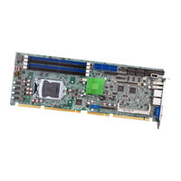
Full-size PICMG 1.3 CPU Card supports LGA1151 Intel Core i7 / i5 / i3 / Pentium / Celeron CPU per Intel Q170, DDR4, VGA/IDP, Dual Intel PCIe GbE, USB 3.0, SATA 6Gb/s, PCIe mini, mSATA, HD Audio, iAMT, iRIS-2400 and RoHS
Brand:
IEI Technology
| Category:
Motherboard
| Size: 0 MB
Advertisement
Related Products
IEI Technology PCIE-G41A2
IEI Technology PCIE-G41A
IEI Technology PCIE-Q57A
IEI Technology PCIE-Q670-R10
IEI Technology PCIE-Q670-DVI-R10
IEI Technology PCIE-Q670-R20
IEI Technology PCIE-Q870-i2
IEI Technology PCIE-H810
IEI Technology PCISA-9652
IEI Technology PM-PV-D5251
IEI Technology Categories
Motherboard
Touch Panel
Computer Hardware
Single board computers
Desktop
More IEI Technology Manuals
Login
Sign In
OR
Sign in with Facebook
Sign in with Google
Upload manual
Upload from disk
Upload from URL