
Related Manuals for Altronix StrikeIt1V


Summary of Contents for Altronix StrikeIt1V
- Page 1 Panic Device Power Controller Installation Guide More than just power. Rev. 052915...
-
Page 2: Table Of Contents
NEC Power-Limited Wiring Requirements for StrikeIt1V Model . . . . . . . . . . . . . . . . . -
Page 3: Overview
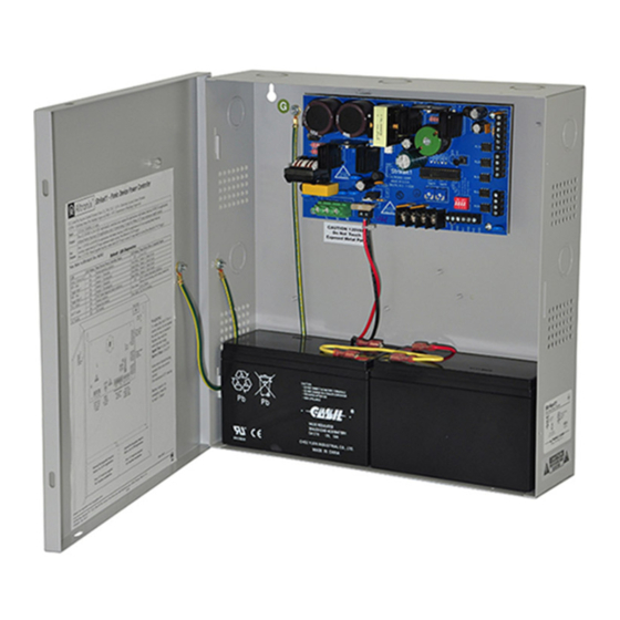
Overview: Altronix StrikeIt1V will operate up to two (2) 24VDC panic hardware devices simultaneously . It is designed to handle the high current surge panic hardware locking devices demand . Each lock output has an adjustable relock delay timer . It will control a pair of doors simultaneously or independently control two individual doors . It has a follower relay for each output to trigger external relays, ADA push plate switches, etc . -
Page 4: Strikeit1V Installation Instructions
9 . To hookup the Fire Alarm Disconnect feature, wire the normally closed (NC) dry contact output from a Fire Alarm Control Panel to the terminals marked [FACP] and [GND] of StrikeIt1V . The “FA Select” DIP switch [SW4] provides two (2) modes of operation (Fig. 3b, pg. 9):... -
Page 5: Strikeit1V Led Diagnostics
To ensure proper connection and operation of the Fire Alarm disconnect hookup, remove wire from the terminal marked [FACP] on StrikeIt1V . With the DIP switch [SW4] in ON positon, unlocked Panic Hardware Devices will unlock . With DIP switch [SW4] in the OFF position (Fig. -
Page 6: Strikeit1V Terminal Identification
StrikeIt1V Terminal Identification: Terminal Legend Function/Description L, G, N Connect 220VAC, 50/60 Hz to these terminals: L to Hot, N to Neutral . + 12VDC – 12VDC Auxiliary Output @ 0 .75A in alarm, 0 .5A in stand-by . 24VDC Auxiliary Output @ 0 .75A . - Page 7 StrikeIt1V - 7 -...
- Page 8 - 8 - StrikeIt1V...
- Page 9 Stand-by Battery Stand-by Battery C NO C NO C NO C NO Note: StrikeIt1V is intended for use with VON DUPRIN ® panic hardware devices. VON DUPRIN ® is a registered trademark of Allegion . Optional Rechargeable Stand-by Battery StrikeIt1V...
-
Page 10: Nec Power-Limited Wiring Requirements For Strikeit1V Model
NEC Power-Limited Wiring Requirements for StrikeIt1V Model: Power-limited and non power-limited circuit wiring must remain separated in the cabinet . All power-limited circuit wiring must remain at least 0 .25” away from any non power-limited circuit wiring . Furthermore, all power-limited circuit wiring and non power-limited circuit wiring must enter and exit the cabinet through differ- ent conduits . - Page 11 Notes: StrikeIt1V - 11 -...
- Page 12 Altronix is not responsible for any typographical errors . 140 58th Street, Brooklyn, New York 11220 USA | phone: 718-567-8181 | fax: 718-567-9056 website: www .altronix .com | e-mail: info@altronix .com | Lifetime Warranty | Made in U .S .A . MEMBER...
Need help?
Do you have a question about the StrikeIt1V and is the answer not in the manual?
Questions and answers