Table of Contents
Advertisement
Quick Links
The ADS7066 Evaluation Module (EVM) Performance Demonstration Kit (PDK) allows users to evaluate
the functionality of Texas Instruments' ADS7066 16-bit, eight-channel programmable successive
approximation register (SAR) analog-to-digital converter (ADC). The ADS7066 device showcases eight
inputs, each configurable to an analog input, digital output, or digital input. The device supports an internal
reference as well as operation with an external reference. This user's guide describes both the hardware
platform showcasing the ADS7066 device and the graphical user interface (GUI) software used to
configure the various modes of operation of this device. It includes complete circuit descriptions,
schematic diagrams, and a bill of materials. The EVM-PDK eases the evaluation of the ADS7066 device
with hardware, software, and computer connectivity through the universal serial bus (USB) interface.
The following related documents are available through the Texas Instruments website at www.ti.com.
SBAU342A – February 2020 – Revised June 2020
Submit Documentation Feedback
ADS7066EVM-PDK Evaluation Module
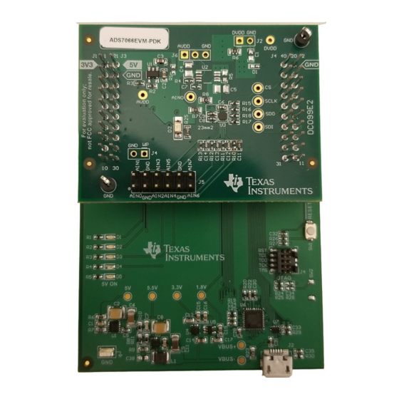
Figure 1. ADS7066EVM-PDK Assembled
Table 1. Related Documentation
Device
ADS7066
REF6025
OPA325
TPS78001
Copyright © 2020, Texas Instruments Incorporated
SBAU342A – February 2020 – Revised June 2020
Literature Number
SBAS928
SBOS708B
SBOS637D
SBVS083E
ADS7066EVM-PDK Evaluation Module
User's Guide
1
Advertisement
Table of Contents

Related Manuals for Texas Instruments ADS7066EVM-PDK


Summary of Contents for Texas Instruments ADS7066EVM-PDK
-
Page 1: Ads7066Evm-Pdk Assembled
The EVM-PDK eases the evaluation of the ADS7066 device with hardware, software, and computer connectivity through the universal serial bus (USB) interface. Figure 1. ADS7066EVM-PDK Assembled The following related documents are available through the Texas Instruments website at www.ti.com. Table 1. Related Documentation Device... -
Page 2: Table Of Contents
Chrome is a trademark of Google. Firefox is a trademark of Mozilla. All other trademarks are the property of their respective owners. ADS7066EVM-PDK Evaluation Module SBAU342A – February 2020 – Revised June 2020 Submit Documentation Feedback Copyright © 2020, Texas Instruments Incorporated... -
Page 3: Introduction
AVDD 5.0 V SCLK AINx/GPIOx ADS7066 Host MCU 330 pF Figure 2. Channel 1 to Channel 6 Hardware Block Diagram SBAU342A – February 2020 – Revised June 2020 ADS7066EVM-PDK Evaluation Module Submit Documentation Feedback Copyright © 2020, Texas Instruments Incorporated... -
Page 4: Ads7066Evm Overview
(GPIOs), digital interface, and provide power supply to the ADS7066 device. Figure 3 shows an ADS7066 board overview. Figure 3. ADS7066 EVM Board ADS7066EVM-PDK Evaluation Module SBAU342A – February 2020 – Revised June 2020 Submit Documentation Feedback Copyright © 2020, Texas Instruments Incorporated... -
Page 5: Channel Connections
3.3V. There is an unpopulated option to use a low-dropout (LDO) regulator, for the TPS78001 for AVDD. There is an onboard option to use an external power supply for DVDD through J2. SBAU342A – February 2020 – Revised June 2020 ADS7066EVM-PDK Evaluation Module Submit Documentation Feedback Copyright © 2020, Texas Instruments Incorporated... -
Page 6: Ads7066 Evm Initial Setup
The EVM and PAMboard come packaged separately. For correct functionality, the boards need to be installed properly. To install the EVM to the PAMboard, stack the ADS7066EVM-PDK board on the PAMBoard. Make sure the 20-pin connector (J1, J3) on the ADS7066 is mapped to left connector on the PAMBoard, and the EVM connector (J4, J2) is mapped to right connector on the PAMBoard. -
Page 7: Browser Extension And Ti Cloud Agent Installation
Hardware Connected shows. Figure 5. Browser Extension and TI Cloud Agent Installation Figure 6. Hardware Connected Successfully to GUI SBAU342A – February 2020 – Revised June 2020 ADS7066EVM-PDK Evaluation Module Submit Documentation Feedback Copyright © 2020, Texas Instruments Incorporated... -
Page 8: Ads7066 Gui Landing Page
GUI, there is an option to connect and disconnect the hardware from the GUI. Figure 7. ADS7066 GUI Landing Page ADS7066EVM-PDK Evaluation Module SBAU342A – February 2020 – Revised June 2020 Submit Documentation Feedback Copyright © 2020, Texas Instruments Incorporated... -
Page 9: Ads7066 Device Configuration Tab Displaying Mode Configuration
The device powers up in manual mode and can be configured into any of the functional modes by writing the configuration registers for the desired mode. Figure 8. ADS7066 Device Configuration Tab Displaying Mode Configuration SBAU342A – February 2020 – Revised June 2020 ADS7066EVM-PDK Evaluation Module Submit Documentation Feedback Copyright © 2020, Texas Instruments Incorporated... -
Page 10: Digital Input Or Output Configurations
Through this document, as an example, channel 0 to 5 will be selected as analog inputs, channel 6 as a digital input, and channel 7 as a digital output. Figure 9. Digital Input or Output Configurations ADS7066EVM-PDK Evaluation Module SBAU342A – February 2020 – Revised June 2020 Submit Documentation Feedback Copyright © 2020, Texas Instruments Incorporated... -
Page 11: Averaging Page
The polynomial is calculated on the CRC-8-ATM as shown in the page. Figure 11. CRC Function Polynomial SBAU342A – February 2020 – Revised June 2020 ADS7066EVM-PDK Evaluation Module Submit Documentation Feedback Copyright © 2020, Texas Instruments Incorporated... -
Page 12: Ads7066 Data Capture Tab
Digital Inputs: The enabled digital input channels are displayed in this page. Section 3.3.3.1 for more information on capturing data. Figure 12. ADS7066 Data Capture Tab ADS7066EVM-PDK Evaluation Module SBAU342A – February 2020 – Revised June 2020 Submit Documentation Feedback Copyright © 2020, Texas Instruments Incorporated... -
Page 13: Analog Ip Data Capture Tab Options
Within the Analog IP page, the captured samples can be displayed in three different formats: • Time Domain • Fast Fourier Transform (FFT) • Histogram Figure 13. Analog IP Data Capture Tab Options SBAU342A – February 2020 – Revised June 2020 ADS7066EVM-PDK Evaluation Module Submit Documentation Feedback Copyright © 2020, Texas Instruments Incorporated... -
Page 14: Time Domain Display
The data can also be exported by clicking the last icon at the right corner of the graph display. Figure 14. Time Domain Display ADS7066EVM-PDK Evaluation Module SBAU342A – February 2020 – Revised June 2020 Submit Documentation Feedback Copyright © 2020, Texas Instruments Incorporated... -
Page 15: Fft Display
NOTE: This image was taken using a incomplete version of the GUI. The device and EVM can perform to data sheet specifications. The latest GUI version available will show correct performance results Figure 15. FFT Display SBAU342A – February 2020 – Revised June 2020 ADS7066EVM-PDK Evaluation Module Submit Documentation Feedback Copyright © 2020, Texas Instruments Incorporated... -
Page 16: Histogram Graph Display
The conversion results can also be shown as a histogram through the histogram tab (shown in Figure within the Analog IP page. Figure 16. Histogram Graph Display ADS7066EVM-PDK Evaluation Module SBAU342A – February 2020 – Revised June 2020 Submit Documentation Feedback Copyright © 2020, Texas Instruments Incorporated... -
Page 17: Digital Input
6 was configured as a digital input. All digital input channels enabled will be displayed on this page and indicate the present logic state, respectively. Figure 17. Digital Input Page Display SBAU342A – February 2020 – Revised June 2020 ADS7066EVM-PDK Evaluation Module Submit Documentation Feedback Copyright © 2020, Texas Instruments Incorporated... -
Page 18: Ads7066 Register Map Page
GUI as desired, and then export the respective register addresses and content to reference when creating firmware. Figure 18. ADS7066 Register Map Page ADS7066EVM-PDK Evaluation Module SBAU342A – February 2020 – Revised June 2020 Submit Documentation Feedback Copyright © 2020, Texas Instruments Incorporated... -
Page 19: Input Signal-Conditioning Block On The Ads7066Evm
3.3 V AVDD AVDD 5.0 V ± SCLK ADS7066 OPA325 Host MCU AIN0 Figure 19. Channel 0 Input Signal Conditioning Block SBAU342A – February 2020 – Revised June 2020 ADS7066EVM-PDK Evaluation Module Submit Documentation Feedback Copyright © 2020, Texas Instruments Incorporated... -
Page 20: Bill Of Materials, Printed Circuit Board Layout, And Schematics
Texas Instruments RTE0016C_WF (WQFN-16) I2C BUS EEPROM (2-Wire), TSSOP-B8 BR24G32FVT-3AGE2 Texas Instruments CMOS Amplifier 1 Circuit Rail-to-Rail SOT-23-5 OPA325IDBVR Texas Instruments ADS7066EVM-PDK Evaluation Module SBAU342A – February 2020 – Revised June 2020 Submit Documentation Feedback Copyright © 2020, Texas Instruments Incorporated... -
Page 21: Ads7066 Evm Pcb Top Layer
Figure 21. ADS7066 EVM PCB Ground Layer Figure 22. ADS7066 EVM PCB Power Plane Layer Figure 23. ADS7066 EVM PCB Bottom Layer SBAU342A – February 2020 – Revised June 2020 ADS7066EVM-PDK Evaluation Module Submit Documentation Feedback Copyright © 2020, Texas Instruments Incorporated... -
Page 22: Ads7066 Evm Schematic Diagram
To By pass op amp, Remove R21 and place on R26 PEC06DAAN AGND AGND Figure 24. ADS7066 EVM Schematic Diagram ADS7066EVM-PDK Evaluation Module SBAU342A – February 2020 – Revised June 2020 Submit Documentation Feedback Copyright © 2020, Texas Instruments Incorporated... - Page 23 Changes from Original (February 2020) to A Revision ....................Page ............... • Updated many portions of EVM user's guide for release to market. SBAU342A – February 2020 – Revised June 2020 Revision History Submit Documentation Feedback Copyright © 2020, Texas Instruments Incorporated...
- Page 24 STANDARD TERMS FOR EVALUATION MODULES Delivery: TI delivers TI evaluation boards, kits, or modules, including any accompanying demonstration software, components, and/or documentation which may be provided together or separately (collectively, an “EVM” or “EVMs”) to the User (“User”) in accordance with the terms set forth herein.
- Page 25 www.ti.com Regulatory Notices: 3.1 United States 3.1.1 Notice applicable to EVMs not FCC-Approved: FCC NOTICE: This kit is designed to allow product developers to evaluate electronic components, circuitry, or software associated with the kit to determine whether to incorporate such items in a finished product and software developers to write software applications for use with the end product.
- Page 26 www.ti.com Concernant les EVMs avec antennes détachables Conformément à la réglementation d'Industrie Canada, le présent émetteur radio peut fonctionner avec une antenne d'un type et d'un gain maximal (ou inférieur) approuvé pour l'émetteur par Industrie Canada. Dans le but de réduire les risques de brouillage radioélectrique à...
- Page 27 www.ti.com EVM Use Restrictions and Warnings: 4.1 EVMS ARE NOT FOR USE IN FUNCTIONAL SAFETY AND/OR SAFETY CRITICAL EVALUATIONS, INCLUDING BUT NOT LIMITED TO EVALUATIONS OF LIFE SUPPORT APPLICATIONS. 4.2 User must read and apply the user guide and other available documentation provided by TI regarding the EVM prior to handling or using the EVM, including without limitation any warning or restriction notices.
- Page 28 Notwithstanding the foregoing, any judgment may be enforced in any United States or foreign court, and TI may seek injunctive relief in any United States or foreign court. Mailing Address: Texas Instruments, Post Office Box 655303, Dallas, Texas 75265 Copyright © 2019, Texas Instruments Incorporated...
- Page 29 TI products. TI’s provision of these resources does not expand or otherwise alter TI’s applicable warranties or warranty disclaimers for TI products. Mailing Address: Texas Instruments, Post Office Box 655303, Dallas, Texas 75265 Copyright © 2020, Texas Instruments Incorporated...
Need help?
Do you have a question about the ADS7066EVM-PDK and is the answer not in the manual?
Questions and answers