Table of Contents
Advertisement
Quick Links
This user's guide describes the characteristics, operation, and use of the ADS794xEVM by itself and as
part of the ADS794xEVM-PDK kit. These evaluation modules (EVMs) allow evaluation of all aspects of
either the
ADS7946
power, differential successive-approximation-register (SAR) analog-to-digital converters (ADCs) with a
maximum throughput rate of 2 MSPS. The ADS7945 offers fully-differential input voltages while the
pseudo-differential inputs of the ADS7946 offer single-ended input voltages with small common-mode
noise-cancelling capabilities. Complete circuit descriptions, schematic diagrams, and bill of materials are
included in this document.
The following related documents are available through the Texas Instruments web site at
http://www.ti.com.
ADCPro is a trademark of Texas Instruments.
Windows XP is a registered trademark of Microsoft Corporation.
SPI is a trademark of Motorola, Inc.
All other trademarks are the property of their respective owners.
SBAU194B – August 2011 – Revised September 2017
Submit Documentation Feedback
ADS794xEVM and ADS794xEVM-PDK
ADS794xEVM-PDK
or
ADS7945
devices (ADS794x). Both devices are 14-bit, dual-channel, ultralow-
Table 1. Related Documentation
Device
ADS7945
ADS7946
OPA350
OPA836
REF5040
SN74LVC2G74
Copyright © 2011–2017, Texas Instruments Incorporated
SBAU194B – August 2011 – Revised September 2017
Literature Number
SBAS539
SBOS099C
SLOS712B
SBOS410E
SCES203M
ADS794xEVM and ADS794xEVM-PDK
User's Guide
1
Advertisement
Table of Contents

Related Manuals for Texas Instruments ADS794xEVM


Summary of Contents for Texas Instruments ADS794xEVM
-
Page 1: Related Documentation
SBAU194B – August 2011 – Revised September 2017 ADS794xEVM and ADS794xEVM-PDK ADS794xEVM-PDK This user's guide describes the characteristics, operation, and use of the ADS794xEVM by itself and as part of the ADS794xEVM-PDK kit. These evaluation modules (EVMs) allow evaluation of all aspects of either the... -
Page 2: Table Of Contents
..................ADS794xEVM-PDK Kit Operation ................ Bill of Materials, Board Layout, and Schematic ........................Schematic List of Figures ................ADS794xEVM and ADS7945 Analog Inputs ................ADS794xEVM and ADS7946 Analog Inputs ................ADS794xEVM Default Jumper Locations ..................ADS794xEVM-PDK Plug-In Installer ................Completed ADS794xEVM-PDK Installer .................... -
Page 3: Evm Overview
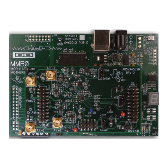
The MMB0 motherboard allows the ADS794xEVM to be connected to the computer via an available USB port. This manual shows how to use the MMB0 as part of the ADS794xEVM-PDK, but does not provide technical details about the MMB0 itself. -
Page 4: Analog Interface
Analog Interface The ADS794xEVM is designed for easy interfacing to multiple analog sources. SMA connectors allow the EVM to have input signals connected via coaxial cables. In addition, the Samtec connector provides a convenient 10-pin, dual-row, header/socket combination at P2. This header/socket provides access to the analog input pins of the ADS794x. -
Page 5: Ads794Xevm And Ads7945 Analog Inputs
EVM Operation section explains in detail how this offset is used to allow bipolar signals for the ADS7945 with jumper J6. Figure 1 illustrates the ADS794xEVM analog inputs with the ADS7945 installed. ADS7945 OPA836 in Inverting AIN0N (pin 6) Configuration... -
Page 6: Ads794Xevm And Ads7946 Analog Inputs
The EVM Operation section explains in detail how this offset is used to allow bipolar signals for the ADS7946 with jumper J6. Figure 2 shows the ADS794xEVM analog inputs with the ADS7946 installed. ADS7946 No SMA AIN0N (pin 6) Open... -
Page 7: Digital Interface
The ADS794x ADC uses SPI serial communication in mode 0 (CPOL = 0, CPHA = 0). Because the serial clock (SCLK) frequency can be as fast as 40 MHz, the ADS794xEVM offers 47-Ω resistors between the SPI signals and P1 to aid with signal integrity. Typically, in high-speed SPI communication, fast signal edges can cause overshoot;... -
Page 8: Power Supplies
Digital Power Options The ADS794xEVM uses a jumper in J3 to connect the digital power supply to either +3.3 VD (P3.10) or +5 VD (P3.9). J3 in position 1-2 connects the digital power supply to +5 VD; position 2-3 connects the digital power supply to +3.3 VD. -
Page 9: Evm Operation
Texas Instruments, or the MMB0 if purchased as part of the ADS794xEVM-PDK. For a list of compatible interface and/or accessory boards for the EVM or the ADS794x, see the relevant product folder on the TI web site. -
Page 10: Ads794Xevm-Pdk: Software Installation
Figure 3. ADS794xEVM Default Jumper Locations There are four jumpers on the ADS794xEVM board. These jumpers are used to set the CS signal entry pin (J1), select the digital logic level (J3), select the reference (J2), and to establish the input signal range type (J6). -
Page 11: Ads794Xevm-Pdk Plug-In Installer
#> refers to the installation file version number, and increments with software version releases). Double- click the file to run it; then follow the instructions as shown. You can also use the ADCPro Update Check feature to check for newer versions of the ADS794xEVM-PDK plug-in, once you have installed a version of it. -
Page 12: Mmb0 Jumper Locations
• J12 must be closed. This setting allows the external supply to power up the MMB0 and the ADS794xEVM through J2 (6-VDC input), and regulate down to +5 V, 3.3 V, and 1.8 V. • J13B must be closed. This configuration connects the 5-V analog power supply with the 5-V digital power supply. -
Page 13: Connecting Ads794Xevm To Mmb0
3.3 V. The MMB0 uses 3.3-V logic to communicate with the ADS7945xEVM. Step 5. Set jumper J1 on the ADS794xEVM to position 2-3 in order to place the CS signal in P1.7 of the EVM. The MMB0 sends the CS signal via P1.7. -
Page 14: Powering Up Ads794Xevm-Pdk
First-Time Connection: ADS794xEVM-PDK to PC, Completing Driver Installation The first time that the ADS794xEVM-PDK kit is connected to the PC via USB, the PC prompts the user for two drivers. At this point, it is presumed that the ADCPro software and the ADS794xEVM plug-in have been installed, and that the ADS794xEVM-PDK kit is properly configured and powered up (refer to Section 6.1... -
Page 15: Ni-Visa Driver Installation Prompt
Figure 9. NI-VISA Driver Installation Prompt 6.5.2 USBStyx Driver Installation The USBStyx driver prompt only appears when the ADCPro software uses the ADS794xEVM plug-in to communicate with the PDK hardware for the first time. Follow these procedures to install the USBStyx driver. -
Page 16: Usbstyx Driver Installation Prompt
Exit button in the small-pop up window. Step 6. Close ADCPro after the USBStyx driver has been installed. ADS794xEVM and ADS794xEVM-PDK SBAU194B – August 2011 – Revised September 2017 Submit Documentation Feedback Copyright © 2011–2017, Texas Instruments Incorporated... -
Page 17: Ads794Xevm-Pdk Kit Operation
The following sections describe how to use ADCPro and the ADS794xEVM plug-in to acquire data. About the MMB0 The MMB0 provides the USB interface between the PC and the ADS794xEVM. The MMB0 is a modular EVM system motherboard. It is designed around the TMS320VC5507, a DSP with an onboard USB interface from Texas Instruments. -
Page 18: Ads794Xevm Plug-In: Device Configuration Tab
The ADS794xEVM plug-in allows the user to evaluate the ADS794x ADC. Figure 12 shows the device configuration tab of the ADS794xEVM Plug-in. Use this tab of the ADCPro software to configure the ADS794x. Figure 12. ADS794xEVM Plug-in: Device Configuration Tab The device configuration tab contains the following controls. -
Page 19: Adcpro Test Plug-Ins
ADS794xEVM-PDK Kit Operation www.ti.com Loading the Test Plug-in Once the ADS794xEVM plug-in is configured in ADCPro, one of the four test plug-ins must be loaded in ADCPro using the drop-down Test menu, as shown in Figure 13. Note that only one Test plug-in can be loaded at a time. -
Page 20: Bill Of Materials, Board Layout, And Schematic
Bill of Materials, Board Layout, and Schematic www.ti.com Bill of Materials, Board Layout, and Schematic Schematics for the ADS794xEVM are appended to this user's guide. The bill of materials is provided in Table Section 8.2 shows the PCB layouts for the ADS794xEVM. - Page 21 Bill of Materials, Board Layout, and Schematic www.ti.com Table 6. ADS794xEVM Bill of Materials (continued) Item No. ADS7945 ADS7946 Ref Des Description Vendor Part Number R20, R21, R26, Resistor, Thick Film Chip, 1%, Vishay/Dale CRCW06034R99FKEA 1/10W, 0603 R16, R17, R24, Resistor, Metal Film Chip, 0.1%,...
-
Page 22: Ads794Xevm Pcb: Top Layer
PCB layouts for the ADS794xEVM. NOTE: Board layouts are not to scale. These figures are intended to show how the board is laid out; they are not intended to be used for manufacturing ADS794xEVM PCBs. Figure 14. ADS794xEVM PCB: Top Layer Figure 15. -
Page 23: Ads794Xevm Pcb: Power Layer
Bill of Materials, Board Layout, and Schematic www.ti.com Figure 16. ADS794xEVM PCB: Power Layer Figure 17. ADS794xEVM PCB: Bottom Layer SBAU194B – August 2011 – Revised September 2017 ADS794xEVM and ADS794xEVM-PDK Submit Documentation Feedback Copyright © 2011–2017, Texas Instruments Incorporated... -
Page 24: Schematic
1000p 1000p 2.2p A1(+) A1(-) 0.1u +5VA AGND UN_POL_VCM AGND 1000p OPA836IDBVT AGND 2.2p 4.99 A1(-) Figure 18. EVM Schematic ADS794xEVM and ADS794xEVM-PDK SBAU194B – August 2011 – Revised September 2017 Submit Documentation Feedback Copyright © 2011–2017, Texas Instruments Incorporated... - Page 25 Replaced reference of wall supply to external supply................• Replaced reference of wall supply to external supply.................. • Modified Powering Up ADS794xEVM-PDK image. SBAU194B – August 2011 – Revised September 2017 Revision History Submit Documentation Feedback Copyright © 2011–2017, Texas Instruments Incorporated...
- Page 26 STANDARD TERMS FOR EVALUATION MODULES Delivery: TI delivers TI evaluation boards, kits, or modules, including any accompanying demonstration software, components, and/or documentation which may be provided together or separately (collectively, an “EVM” or “EVMs”) to the User (“User”) in accordance with the terms set forth herein.
- Page 27 FCC Interference Statement for Class B EVM devices NOTE: This equipment has been tested and found to comply with the limits for a Class B digital device, pursuant to part 15 of the FCC Rules. These limits are designed to provide reasonable protection against harmful interference in a residential installation.
- Page 28 【無線電波を送信する製品の開発キットをお使いになる際の注意事項】 開発キットの中には技術基準適合証明を受けて いないものがあります。 技術適合証明を受けていないもののご使用に際しては、電波法遵守のため、以下のいずれかの 措置を取っていただく必要がありますのでご注意ください。 1. 電波法施行規則第6条第1項第1号に基づく平成18年3月28日総務省告示第173号で定められた電波暗室等の試験設備でご使用 いただく。 2. 実験局の免許を取得後ご使用いただく。 3. 技術基準適合証明を取得後ご使用いただく。 なお、本製品は、上記の「ご使用にあたっての注意」を譲渡先、移転先に通知しない限り、譲渡、移転できないものとします。 上記を遵守頂けない場合は、電波法の罰則が適用される可能性があることをご留意ください。 日本テキサス・イ ンスツルメンツ株式会社 東京都新宿区西新宿6丁目24番1号 西新宿三井ビル 3.3.3 Notice for EVMs for Power Line Communication: Please see http://www.tij.co.jp/lsds/ti_ja/general/eStore/notice_02.page 電力線搬送波通信についての開発キットをお使いになる際の注意事項については、次のところをご覧ください。http:/ /www.tij.co.jp/lsds/ti_ja/general/eStore/notice_02.page 3.4 European Union 3.4.1 For EVMs subject to EU Directive 2014/30/EU (Electromagnetic Compatibility Directive): This is a class A product intended for use in environments other than domestic environments that are connected to a low-voltage power-supply network that supplies buildings used for domestic purposes.
- Page 29 Notwithstanding the foregoing, any judgment may be enforced in any United States or foreign court, and TI may seek injunctive relief in any United States or foreign court. Mailing Address: Texas Instruments, Post Office Box 655303, Dallas, Texas 75265 Copyright © 2017, Texas Instruments Incorporated...
- Page 30 IMPORTANT NOTICE FOR TI DESIGN INFORMATION AND RESOURCES Texas Instruments Incorporated (‘TI”) technical, application or other design advice, services or information, including, but not limited to, reference designs and materials relating to evaluation modules, (collectively, “TI Resources”) are intended to assist designers who are developing applications that incorporate TI products;...
- Page 31 Mouser Electronics Authorized Distributor Click to View Pricing, Inventory, Delivery & Lifecycle Information: Texas Instruments ADS7945EVM-PDK...
Need help?
Do you have a question about the ADS794xEVM and is the answer not in the manual?
Questions and answers