Table of Contents
Advertisement
Quick Links
www.ti.com
User's Guide
ADS7038Q1EVM-PDK Evaluation Module
The ADS7038-Q1 Evaluation Module (EVM) Performance Demonstration Kit (PDK) allows users to evaluate the
functionality of Texas Instruments' ADS7038-Q1 12-bit, eight-channel programmable successive approximation
register (SAR) analog-to-digital converter (ADC). The ADS7038-Q1 device showcases eight inputs, each
configurable to an analog input, digital output, or digital input. This user's guide describes both the hardware
platform showcasing the ADS7038-Q1 device and the graphical user interface (GUI) software used to configure
the various modes of operation of this device. It includes complete circuit descriptions, schematic diagrams, and
a bill of materials. The EVM-PDK eases the evaluation of the ADS7038-Q1 device with hardware, software, and
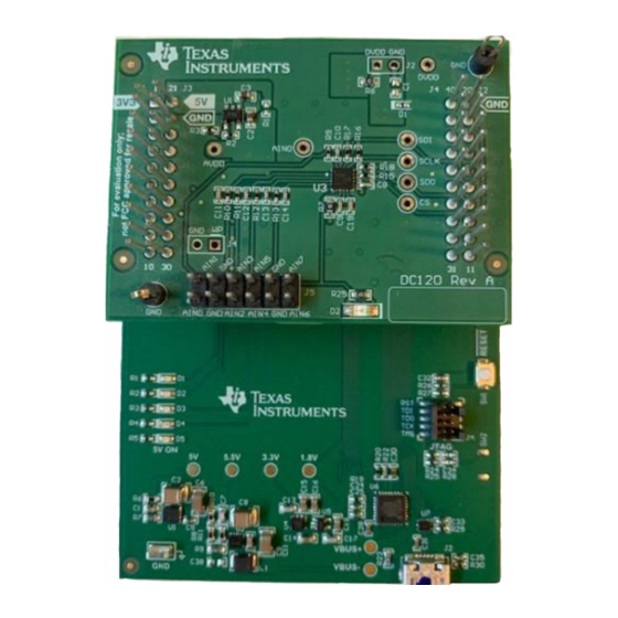
computer connectivity through the universal serial bus (USB) interface. The following figure shows the
ADS7038Q1EVM-PDK.
SBAU279 – OCTOBER 2020
Submit Document Feedback
ABSTRACT
ADS7038Q1EVM-PDK
Copyright © 2020 Texas Instruments Incorporated
ADS7038Q1EVM-PDK Evaluation Module
1
Advertisement
Table of Contents

Related Manuals for Texas Instruments ADS7038-Q1


Summary of Contents for Texas Instruments ADS7038-Q1
- Page 1 It includes complete circuit descriptions, schematic diagrams, and a bill of materials. The EVM-PDK eases the evaluation of the ADS7038-Q1 device with hardware, software, and computer connectivity through the universal serial bus (USB) interface. The following figure shows the ADS7038Q1EVM-PDK.
-
Page 2: Table Of Contents
Table of Contents www.ti.com The following related documents are available through the Texas Instruments website at www.ti.com Device Literature Number ADS7038 SBAS979 ADS7038-Q1 SBAS981 TLV9061 SBOS839 TLV78001 SBVS083 Table of Contents Introduction.....................................3 2 ADS7038Q1EVM-PDK Overview............................4 2.1 Connections to Input Channels............................ -
Page 3: Introduction
The ADS7038-Q1 EVM requires an external master controller to evaluate the ADS7038-Q1 device. The PAMBoard is controlled by commands received from the ADS7038-Q1 GUI, and returns data to the GUI for display and analysis. If the PAMBoard is not used, the EVM plug-in module format allows for an alternative external host to communicate with the ADS7038-Q1 by easily connecting through a pin header. -
Page 4: Ads7038Q1Evm-Pdk Overview
2 ADS7038Q1EVM-PDK Overview This section describes various onboard components that are used to interface the analog input, general purpose inputs/outputs (GPIOs), digital interface, and provide power supply to the ADS7038-Q1 device. Figure 2-1 shows an ADS7038Q1EVM-PDK board overview. Figure 2-1. ADS7038Q1EVM-PDK Top Layer Overview 2.1 Connections to Input Channels... -
Page 5: Digital Interface
1, the ADS7038Q1EVM interfaces with the PAMBoard, which in turn communicates with the computer over the USB. The two devices on the EVM that communicate over SPI are the ADS7038-Q1 ADC (U3) and the electrically erasable programmable read-only memory (EEPROM) (U4). The EEPROM is preprogrammed with the information required to configure and initialize the ADS7038 platform. -
Page 6: Ads7038Q1Evm-Pdk Initial Setup
To install the EVM to the PAMboard, stack the ADS7038Q1EVM board on the PAMBoard. Make sure the 20-pin connector (J1, J3) on the ADS7038Q1EVM is mapped to left connector on the PAMBoard, and the EVM connector (J4, J2) is mapped to right connector on the PAMBoard. The silk screen on the ADS7038-Q1 must match with the PAMBoard. -
Page 7: Figure 3-2. Browser Extension And Ti Cloud Agent Installation
Hardware Connected shows. Figure 3-2. Browser Extension and TI Cloud Agent Installation Figure 3-3. Hardware Connected Successfully to GUI SBAU279 – OCTOBER 2020 ADS7038Q1EVM-PDK Evaluation Module Submit Document Feedback Copyright © 2020 Texas Instruments Incorporated... -
Page 8: Ads7038Q1Evm-Pdk Gui Overview
EEPROM. When detected and connected, the GUI indicates this status as Connected. At the bottom left corner of the GUI, there is an option to connect and disconnect the hardware from the GUI. Figure 3-4. ADS7038Q1EVM-PDK GUI Landing Page ADS7038Q1EVM-PDK Evaluation Module SBAU279 – OCTOBER 2020 Submit Document Feedback Copyright © 2020 Texas Instruments Incorporated... -
Page 9: Figure 3-5. Device Configuration Tab
The device powers up in manual mode and can be configured into any of the functional modes by writing the configuration registers for the desired mode. SBAU279 – OCTOBER 2020 ADS7038Q1EVM-PDK Evaluation Module Submit Document Feedback Copyright © 2020 Texas Instruments Incorporated... -
Page 10: Figure 3-6. Channel Selection Tab
For analog inputs, users can select the high and low thresholds, hysteresis settings. The Alert counter and out-band/in-band settings can be configured by clicking the additional advanced configuration icon. Digital ADS7038Q1EVM-PDK Evaluation Module SBAU279 – OCTOBER 2020 Submit Document Feedback Copyright © 2020 Texas Instruments Incorporated... -
Page 11: Figure 3-7. Channel Configuration Tab - Input
Enabled digital outputs can be configured for different trigger sources and the trigger output conditions. Figure 3-8. Channel Configuration tab - Output Channels SBAU279 – OCTOBER 2020 ADS7038Q1EVM-PDK Evaluation Module Submit Document Feedback Copyright © 2020 Texas Instruments Incorporated... -
Page 12: Figure 3-9. Channel Configuration Tab - Alert
Alert is mapped to CH-7 and will trigger based on the threshold levels for CH0 (AIN0) that were configured in Section (Input Channel Configuration). Figure 3-9. Channel Configuration tab - Alert Configuration ADS7038Q1EVM-PDK Evaluation Module SBAU279 – OCTOBER 2020 Submit Document Feedback Copyright © 2020 Texas Instruments Incorporated... -
Page 13: Figure 3-10. Averaging & Statistics Page
The oversampling ratio applies to all analog input channels enabled. Statistics to show the minimum, maximum, and latest codes can also be enabled here. Figure 3-10. Averaging & Statistics Page SBAU279 – OCTOBER 2020 ADS7038Q1EVM-PDK Evaluation Module Submit Document Feedback Copyright © 2020 Texas Instruments Incorporated... -
Page 14: Figure 3-11. Crc Page
Analog Inputs: The sample and conversion results for each enabled analog input is displayed in this page. The results can be displayed in three methods: time domain, Fast Fourier transform (FFT), and histogram. ADS7038Q1EVM-PDK Evaluation Module SBAU279 – OCTOBER 2020 Submit Document Feedback Copyright © 2020 Texas Instruments Incorporated... -
Page 15: Figure 3-12. Data Capture Tab
Within the Analog IP page, the captured samples can be displayed in three different formats: • Time Domain • Fast Fourier Transform (FFT) • Histogram SBAU279 – OCTOBER 2020 ADS7038Q1EVM-PDK Evaluation Module Submit Document Feedback Copyright © 2020 Texas Instruments Incorporated... -
Page 16: Figure 3-13. Time Domain Data Analysis Display
The data can also be exported by clicking the last icon at the right corner of the graph display. Figure 3-13 shows the time domain display. Figure 3-13. Time Domain Data Analysis Display ADS7038Q1EVM-PDK Evaluation Module SBAU279 – OCTOBER 2020 Submit Document Feedback Copyright © 2020 Texas Instruments Incorporated... -
Page 17: Figure 3-14. Fft Data Analysis Display
SFDR, THD, and SINAD. The effective number of bits (ENOB) and the number harmonics shown is also displayed in the table. Figure 3-14. FFT Data Analysis Display SBAU279 – OCTOBER 2020 ADS7038Q1EVM-PDK Evaluation Module Submit Document Feedback Copyright © 2020 Texas Instruments Incorporated... -
Page 18: Figure 3-15. Histogram Tab
6 was configured as a digital input. All digital input channels enabled will be displayed on this page with the present logic state applied to them. Figure 3-16. Digital Inputs ADS7038Q1EVM-PDK Evaluation Module SBAU279 – OCTOBER 2020 Submit Document Feedback Copyright © 2020 Texas Instruments Incorporated... -
Page 19: Figure 3-17. Register Map
GUI. This allows the user to configure the device easily through the GUI as desired, and then export the respective register addresses and content to reference when creating firmware. Figure 3-17. Register Map SBAU279 – OCTOBER 2020 ADS7038Q1EVM-PDK Evaluation Module Submit Document Feedback Copyright © 2020 Texas Instruments Incorporated... -
Page 20: Input Signal-Conditioning Circuitry On The Ads7038Q1Evm
5 Bill of Materials, Printed Circuit Board Layout, and Schematics This section contains the ADS7038Q1EVM-PDK bill of materials (BOM), printed circuit board (PCB) layout, and schematics. ADS7038Q1EVM-PDK Evaluation Module SBAU279 – OCTOBER 2020 Submit Document Feedback Copyright © 2020 Texas Instruments Incorporated... -
Page 21: Bill Of Materials
RES, 169, 1%, 0.063 W, AEC-Q200 Grade 0, 0402 CRCW0402169RFKED Vishay-Dale 0402 R23, R24 10.0k RES, 10.0 k, 1%, 0.063 W, 0402 0402 RC0402FR-0710KL Yageo America SBAU279 – OCTOBER 2020 ADS7038Q1EVM-PDK Evaluation Module Submit Document Feedback Copyright © 2020 Texas Instruments Incorporated... - Page 22 RES, 0, 1%, 0.1 W, AEC-Q200 Grade 0, 0603 0603 RMCF0603ZT0R00 Stackpole Electronics Unless otherwise noted in the Alternate Part Number or Alternate Manufacturer columns, all parts may be substituted with equivalents. ADS7038Q1EVM-PDK Evaluation Module SBAU279 – OCTOBER 2020 Submit Document Feedback Copyright © 2020 Texas Instruments Incorporated...
-
Page 23: Pcb Layout
5.2 PCB Layout Figure 5-1 illustrates the EVM PCB layouts. Top Layer Inner GND Layer Bottom Layer Inner Pwr Layer Figure 5-1. PCB Layouts SBAU279 – OCTOBER 2020 ADS7038Q1EVM-PDK Evaluation Module Submit Document Feedback Copyright © 2020 Texas Instruments Incorporated... -
Page 24: Schematics
Bill of Materials, Printed Circuit Board Layout, and Schematics www.ti.com 5.3 Schematics Figure 5-2 illustrates the ADS7038Q1EVM-PDK schematics. Figure 5-2. ADS7038Q1EVM-PDK Schematics ADS7038Q1EVM-PDK Evaluation Module SBAU279 – OCTOBER 2020 Submit Document Feedback Copyright © 2020 Texas Instruments Incorporated... - Page 25 STANDARD TERMS FOR EVALUATION MODULES Delivery: TI delivers TI evaluation boards, kits, or modules, including any accompanying demonstration software, components, and/or documentation which may be provided together or separately (collectively, an “EVM” or “EVMs”) to the User (“User”) in accordance with the terms set forth herein.
- Page 26 www.ti.com Regulatory Notices: 3.1 United States 3.1.1 Notice applicable to EVMs not FCC-Approved: FCC NOTICE: This kit is designed to allow product developers to evaluate electronic components, circuitry, or software associated with the kit to determine whether to incorporate such items in a finished product and software developers to write software applications for use with the end product.
- Page 27 www.ti.com Concernant les EVMs avec antennes détachables Conformément à la réglementation d'Industrie Canada, le présent émetteur radio peut fonctionner avec une antenne d'un type et d'un gain maximal (ou inférieur) approuvé pour l'émetteur par Industrie Canada. Dans le but de réduire les risques de brouillage radioélectrique à...
- Page 28 www.ti.com EVM Use Restrictions and Warnings: 4.1 EVMS ARE NOT FOR USE IN FUNCTIONAL SAFETY AND/OR SAFETY CRITICAL EVALUATIONS, INCLUDING BUT NOT LIMITED TO EVALUATIONS OF LIFE SUPPORT APPLICATIONS. 4.2 User must read and apply the user guide and other available documentation provided by TI regarding the EVM prior to handling or using the EVM, including without limitation any warning or restriction notices.
- Page 29 Notwithstanding the foregoing, any judgment may be enforced in any United States or foreign court, and TI may seek injunctive relief in any United States or foreign court. Mailing Address: Texas Instruments, Post Office Box 655303, Dallas, Texas 75265 Copyright © 2019, Texas Instruments Incorporated...
- Page 30 TI products. TI’s provision of these resources does not expand or otherwise alter TI’s applicable warranties or warranty disclaimers for TI products. Mailing Address: Texas Instruments, Post Office Box 655303, Dallas, Texas 75265 Copyright © 2020, Texas Instruments Incorporated...
- Page 31 Mouser Electronics Authorized Distributor Click to View Pricing, Inventory, Delivery & Lifecycle Information: Texas Instruments ADS7038Q1EVM-PDK...
Need help?
Do you have a question about the ADS7038-Q1 and is the answer not in the manual?
Questions and answers