
Related Manuals for Thermo Scientific 1500 A2 Series


Summary of Contents for Thermo Scientific 1500 A2 Series
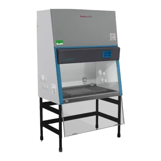
- Page 1 1500 Series A2 Class II, Type A2 Biological Safety Cabinet Operating Manual Rev. 00 Visit us online to register your warranty www.thermoscientific.com/labwarranty...
- Page 2 Dear User, Congratulations on your purchase of a Thermo Scientific 1500 Series Class II, Type A2 biological safety cabinet! Your 1500 Series A2 biological safety cabinet has been tested and certified in accordance to NSF/ANSI 49, and is designed to protect the user, the environment, and your research from harmful substances and cross-contamination.
- Page 3 In no event shall Thermo Fisher Scientific be held liable for any damages, direct or incidental, arising out of or related to the use of this manual. ©2020 Thermo Fisher Scientific. All rights reserved. 1500 Series A2 Thermo Scientific...
- Page 4 Always use the proper protective equipment (clothing, gloves, goggles, etc.) 4 Always dissipate extreme cold or heat and wear protective clothing. 4 Always follow good hygiene practices. 4 Each individual is responsible for his or her own safety. Thermo Scientific Thermo Scientific 1500 Series A2...
- Page 5 We can also provide you with a quotation on our Extended Warranty for your Thermo Scientific products. Whatever Thermo Scientific products you need or use, we will be happy to discuss your applications. If you are experiencing technical problems, working together, we will help you locate the problem and, chances are, correct it yourself...over the telephone without a service...
-
Page 6: Table Of Contents
Settings ..........4-19 Thermo Scientific... - Page 7 Data Log/Warranty ......... . .9-1 1500 Series A2 Thermo Scientific...
-
Page 8: Description
Description Section 1 Figure 1-1. Unit Components The Thermo Scientific 1500 Series A2 offers innovative SmartFlow™ Plus technology; an automatic airflow compensation system that adjusts motor speed as filters load, without the use of a manual damper. The SmartFlow™ Plus system ensures safe working conditions, even between annual certifications. -
Page 9: Safety Systems
Harmful particles are not carried over the sample chamber (protection from cross-contamination). HEPA filters The downflow air within the chamber and the exhaust air are cleaned by HEPA filters. 1500 Series A2 Thermo Scientific... - Page 10 Window position monitoring The position sensors detect the size of the front window opening and indicate whether the window is open to the specified work position, closed (energy saving) or in an unsafe intermediate position. Thermo Scientific 1500 Series A2...
-
Page 11: Hepa Filters
These grids prevent large items such as paper towels and tissues from entering the plenum where they may impair the function of the blowers or the filters. The grids can be easily removed for cleaning. 1500 Series A2 Thermo Scientific... -
Page 12: Use Of The Window
Window Max opening for loading samples Work position Closed position Window Opening height for cleaning window Pillardress panel Pillardress panel Figure 1-3. Window Openings Thermo Scientific 1500 Series A2... - Page 13 To place the window in the closed or reduced mode position, move it to the "STANDBY" position (Figure 1-5) and. Make sure that the window touches the gasket below. dimple Figure 1-4. Work Position Figure 1-5. Fully Closed Position (UV, if applicable) 1500 Series A2 Thermo Scientific...
-
Page 14: Unit Interface
Warning If a gas burner is to be operated in the sample chamber, an appropriate shut-off valve for the gas supply must be installed. Use only laboratory safe burners in the sample chamber. Thermo Scientific 1500 Series A2... -
Page 15: Chamber Lighting
Service valve Figure 1-6. Interfaces (2 of 4 access ports are shown) The Thermo Scientific 1500 Series A2 offers a bright workspace for a Chamber Lighting more comfortable working environment. Models with coated rear and side walls resist glare and make it easier for the user to work safely. -
Page 16: Uv Lights
Warning Work safety is assured only if the armrests are used correctly! Work tray Perforation track Width Armrest Separation Depth distance Armrest Perforation track Holes for padded armrests (Optional) Figure 1-8. Work tray Thermo Scientific 1500 Series A2... -
Page 18: Installation
When positioning the cabinet, make sure the counterweight on the back of the unit can move freely. The minimal distance to the wall or adjacent objects should be 3 inches (7.6 cm), unless upper wall brackets are used. Thermo Scientific 1500 Series A2... -
Page 19: Optional Exhaust Transition
3. Secure the accessory by tightening Threaded inserts the supplied retaining screws (M5) wrench-tight. 4. Using the adjustment nuts on the sliding panel, set the gap height to an opening of 2 inches. Figure 2-1. 4 ft Thimble 1500 Series A2 Thermo Scientific... - Page 20 3. Seal the unused connecting opening with Pipe the cover. Place the cover onto the connecting Sleeve opening at the housing Cover and secure it with the Sleeve screws. Opening Figure 2-2. 6 ft Thimble and Sleeve Thermo Scientific 1500 Series A2...
-
Page 21: Moving The Unit
Warning The weight of the window is balanced by the counterweight on the back of the cabinet. Do not move the unit unless the counterweight has been locked in place with the shipping screws (see Figure 3-2). Figure 2-3. Lift points 1500 Series A2 Thermo Scientific... -
Page 22: Service Valve Connections
7. Secure the service valve to the side panel using the nut. 8. Establish the connection to the supply line using a union nut. Note If a service valve is removed, the service valve port plug should be re-installed. Thermo Scientific 1500 Series A2... - Page 23 If SmartPorts are installed, replace the SmartPort grommet before starting a decontamination procedure. Two replacements (P/N 114111) are Before Decontamination shipped with each unit, or the 1910112 kit containing 4 grommets can be ordered. SmartPort locations are indicated above (one on each side). 1500 Series A2 Thermo Scientific...
-
Page 24: Universal Piping Connections
On 3 cu ft units, the right side access points are next to the right side rope channel. The left side access points are to the left of these. Figure 2-6. Possible Universal Piping Access Points/Drain Valve Thermo Scientific 1500 Series A2... -
Page 25: Smartport
Locate the drain piping underneath the unit on the left side (see Fig 2-6). Apply thread sealant sparingly to the threads. Install the drain valve. Ensure the valve is in the closed position. Be aware of the valve when moving the unit from the stand or workstation. 1500 Series A2 Thermo Scientific... -
Page 26: Start-Up
5. To install the cabinet frame to the stand, insert four flatwashers and Allen screws loosely into the threaded holes at the bottom of the cabinet. Thermo Scientific 1500 Series A2... - Page 27 7. Slide the cabinet frame to the keyhole stop (see Figure. 3-1). 8. Tighten the four Allen screws. 9. Level the cabinet (instructions follow in this section). 1500 Series A2 Thermo Scientific...
-
Page 28: Unlock Counterweight
Check from right to left, and from back to front. Thermo Scientific 1500 Series A2... -
Page 29: Power Connection
The power supply cord is the mains disconnect. Maintain access at all times. If the unit includes service valves (gas, water), the valves must be installed properly to ground, to the unit’s main ground. 1500 Series A2 Thermo Scientific... -
Page 30: Installation Tests
Caution Alarms on this unit are not factory-set. Set the alarms to avoid product loss and ensure personnel safety. Refer to Certification section. Thermo Scientific 1500 Series A2... -
Page 31: Locating A Certifier
PO Box 130140 789 N. Dixboro Rd Ann Arbor, MI 48113-0140 Telephone (734) 769-8010 Or (800) NSF-MARK Fax (734) 769-0109 http://www.nsf.org/Certified/Biohazard-Certifier IAFCA PO Box 12155 Columbus, OH 43212 Telephone (888) 679-1904 Fax (614) 486-1108 http://www.iafca.com/certifier.html 1500 Series A2 Thermo Scientific... - Page 32 Telephone (919) 787-5181 Fax (919) 787-4916 http://www.cetainternational.org/members/corp_indiv.htm Note Unless certification was expressly called for in the specification, quotes and/or purchase order, the cost for this on-site testing is to be paid for by the customer. Thermo Scientific 1500 Series A2...
-
Page 34: Operation
Figure 4-1. Initial Startup: Startup Screen 2. Tap the “Start Setup” button. The initial setup screen appears as shown below, prompting you to choose a display language, set the date and time. Figure 4-2. Initial Setup Thermo Scientific 1500 Series A2... - Page 35 5. Tap the “Finish” button to complete the initial set up. The unit comes up in idle mode, as shown below, assuming that the window is closed. Figure 4-5. Main screen – Unit in Idle Mode 1500 Series A2 Thermo Scientific...
-
Page 36: Operation
The Info & Health Status area (Region 1 in Figure 4-6 above) shows the biological safety cabinet‘s name, the current date and time, the unit‘s overall health status. For an overview, see “Info & Health Status Area” Thermo Scientific 1500 Series A2... - Page 37 Health Status pop-up window on top of the Main Screen. • The following different icons may appear in this place, representing the overall health status of the biological safety cabinet: Model 1500 Series A2 Thermo Scientific...
- Page 38 Figure 4-8 shows the unit in working mode, with the window ready in the working position and the downflow and inflow speeds at operational speeds, and blowers are all on. Figure 4-8. Main Screen Thermo Scientific 1500 Series A2...
- Page 39 R2B) be seen in Figure 4-9. The Control Panel is visible at all times below the Main Screen. Figure 4-9. Control Panel for fully equipped Unit Model 1500 Series A2 Thermo Scientific...
- Page 40 The Main Navigation Bar (in Screen Region R3) holds icons for all major (Region R3) settings of the biological safety cabinets. The Main Navigation Bar is visible at all times on all screens. Figure 4-10. Main Navigation Bar Thermo Scientific 1500 Series A2...
-
Page 41: Startup Mode
A green checkmark icon in the window status box to indicate that the window is ready. • Yellow “Timer” icons with rotating hands show in the Downflow and Inflow boxes, signifying that the airflows are not up to proper speed yet. Model 1500 Series A2 Thermo Scientific... -
Page 42: Working Mode
Power receptacle and UV functions are both off. Standby Mode Figure 4-13 shows the Main Screen in standby mode. Figure 4-13. Main Screen - Unit in Standby Thermo Scientific 1500 Series A2... -
Page 43: Idle Mode
Figure 4-14 shows that it is in Idle mode with the window closed. Idle mode is indicated by the gray “no activity” icons in the downflow and inflow status indicator boxes. Figure 4-14. Main Screen - Unit in Idle Mode, window closed 4-10 Model 1500 Series A2 Thermo Scientific... -
Page 44: Running Uv Disinfection
UV radiation. A safety interlock ensures that the routine cannot be run until the front window is in the closed position. And the LED light must be switched off. Thermo Scientific 1500 Series A2 4-11... - Page 45 Then, the UV lamps are switched off automatically, and the “UV disinfection” screen goes away. Auto UV disinfection The UV disinfection can be started automatically with the specified time if the UV-auto-start function is enabled. Refer to Section 4.13.3. 4-12 Model 1500 Series A2 Thermo Scientific...
-
Page 46: Viewing Status And Replacing Uv Bulb
UV, shows the total UV work hours and the UV bulb install date. • Filter, shows the filter running time, estimated left service time, and the filter install date Figure 4-20. “Status” Main Screen Thermo Scientific 1500 Series A2 4-13... - Page 47 Tap “Yes, Update” button to save your setting, you can also tap “Cancel” button to cancel your setting. If you tapped the “Yes, Update” button, a pop-up screen shown in Figure 4-22 Figure 4-22. UV Reset Saved Pop-up Screen 4-14 Model 1500 Series A2 Thermo Scientific...
-
Page 48: Alarms
“Alarms and Alerts” screen, as explained in “Snooze Timeout”). The “Alarm bell” icon is crossed out to indicate that the audible alarm signal has been snoozed (Figure 4-24). Thermo Scientific 1500 Series A2 4-15... -
Page 49: Handling Alarms
Handling Alarms To handle the problem, proceed as follows: • Inspect the small blue alarm counter in the red “Health Status Alarm” icon to find out how many alarms you have to handle. 4-16 Model 1500 Series A2 Thermo Scientific... -
Page 50: Alerts
These alerts appear with the visual features shown in the example in Figure 4-26. Figure 4-26. “Alert” Screen The “Health Status Alert” icon in the shape of a yellow “Alert triangle” icon appears on a black background. Thermo Scientific 1500 Series A2 4-17... -
Page 51: Handling Alerts
“Health Status Alert” screen one by one. When the last issue has been cleared, the screen display returns to the healthy state and the green “Health Status Good” icon replaces the yellow “Health Status Alert” icon . 4-18 Model 1500 Series A2 Thermo Scientific... -
Page 52: Settings
(meters per second), cmh (cubic meters per hour). imperial units: fpm (feet per minute), cfm (cubic feet per minute). • Date. Please refer to the initial setup process. Thermo Scientific 1500 Series A2 4-19... - Page 53 Snooze button was tapped. Minutes are selectable from a drop-down list. The default setting is 5 minutes. You can tap the “Save” button to save the setting. Figure 4-30. “Alarms and Alerts” Settings Screen 4-20 Model 1500 Series A2 Thermo Scientific...
- Page 54 UV disinfection function by "UV Auto Start". If the Auto UV disinfection function is enabled, you can also set the auto start time by "UV Auto Start Time". • Tap the “Save” button to save the setting. Thermo Scientific 1500 Series A2 4-21...
-
Page 55: Alarm/Alert Log
Tapping the “Data Plate” icon in the “Settings” screen takes you to the unit information shown in Figure 4-33. you can check the unit information • model • serial number • main board firmware version • GUI display board firmware version Figure 4-33. “Data Plate” Screen 4-22 1500 Series A2 Thermo Scientific... -
Page 56: Loading The Chamber
• Do not place accessories into the sample chamber that cause air turbulence or emit excessive heat. • Do not block air circulation at the ventilation slots of the work tray. Thermo Scientific 1500 Series A2 4-23... - Page 57 After completing a procedure, 1. Remove samples from the sample chamber and store them properly. 2. Clean and disinfect the sample chamber surfaces, including the work tray and the drain pan. 3. Clean and disinfect all accessories. 4-24 1500 Series A2 Thermo Scientific...
-
Page 58: Unit Shut-Down
„Mains voltage has been restored“ appears as soon as power has been restored, prompting the user to confirm by tapping OK. This message may, for example, be caused by a power outage. Figure 4-35. Power Supply Connection Thermo Scientific 1500 Series A2 4-25... -
Page 59: Extended Period Shut-Down
Warning As this unit can be used for processing and treating infectious substances, it must be decontaminated prior to disposal, in accordance with acceptable standards and procedures. 4-26 1500 Series A2 Thermo Scientific... -
Page 60: Cleaning / Decontamination
The presence of any liquid or solid that remains in contact with the stainless steel for a prolonged time can prevent oxygen contact and promote corrosion, as can prolonged contact with cleaners or disinfectants containing chlorine, ammonia, iodine or other caustic agents. Thermo Scientific 1500 Series A2... -
Page 61: Cleaning And Caring For Coated Surfaces
Never use abrasive cleaners, scouring pads or steel wool. If the coated surfaces do become dull, streaked, smeared or marred in some other way, there is no known method to restore the finish. 1500 Series A2 Thermo Scientific... -
Page 62: Disinfection
1. Close the front window, the air system operates in the reduced mode. 2. Press the UV key on the control panel. To interrupt or cancel the UV disinfection procedure, just press the UV key (the display shows the operating hours) and slide the window up. Thermo Scientific 1500 Series A2... -
Page 63: Microbiological Space Decontamination
Thermo Fisher Scientific has developed validated procedures for the decontamination of the Thermo Scientific 1500 Series A2 using the Steris VHP (Vaporized Hydrogen Peroxide) system. These procedures are available on request. -
Page 64: Clean The Drain Pan
Retaining down and towards the back until the locking tabs are secured behind the inner back wall. Caution Do not operate the unit without the paper catch grids installed! Figure 5-1. Protective Paper Catch Grid Thermo Scientific 1500 Series A2... -
Page 66: Maintenance
Warning The diffuser plate on the chamber ceiling serves as protection for the downflow filter and prevents refluxing of downflow air. When scanning the filter surface for a leak test, the perforated plate must be removed. Thermo Scientific 1500 Series A2... -
Page 67: Service
The UV bulb is installed in rotating sockets. To remove, rotate the bulb counterclockwise to disengage the latch and remove it from the sockets. 4. To install, slide the bulb contact pins into the rotating socket grooves and rotate the bulb clockwise to latch the sockets. 1500 Series A2 Thermo Scientific... -
Page 68: Replacements And Repairs
Warning As this unit can be used for processing and treating infectious substances, it may become contaminated. Prior to disposal, the entire unit with filters must be decontaminated in accordance with acceptable standards and procedures. Thermo Scientific 1500 Series A2... -
Page 70: Specifications
Distance from back panel SmartPort mm / in 182.9 / 7.2 First access port mm / in 259.0 / 10.2 Second access port mm / in 309.9 / 12.2 Third access port mm / in 360.7 / 14.2 Thermo Scientific 1500 Series A2... - Page 71 Ergonomics Noise level* dB(A) 4ft. models 10”: 63, ±2 6ft models 10”: 65, ±2 *The noise level was determined in accordance with NSF/ANSI 49. The measurement uncertainty is within a range of ± 2 dB. 1500 Series A2 Thermo Scientific...
- Page 72 UL61010-1) Connecting lines Power Cord (>3 m / 10 ft) Mains connection CEE 7/7 Plug with NEMA 5-15 plug * With additional 5A load on cabinet receptacles, blowers at 100% and cabinet lighting switched on. Thermo Scientific 1500 Series A2...
- Page 73 / in 107 / 4.2 Exhaust air Height mm / in 610 / 24 457 / 18 Length mm / in 457 / 18 915 / 36 Depth mm / in 130 / 5.1 1500 Series A2 Thermo Scientific...
-
Page 74: Certification Testing
Velocity of the displacement flow circulating through the work chamber. Exhaust velocity (FPM): Velocity of the airflow discharged through the exhaust filter opening. Exhaust airflow volume (CFM): Amount of air discharged at the exhaust filter. Thermo Scientific 1500 Series A2... -
Page 75: Testing
– Electrical leakage, ground circuit resistance and polarity tests Note Service with costs: Unless certification was expressly called for in the specification, quotes and/or purchase order, the cost for this on-site testing is to be paid for by the customer. 1500 Series A2 Thermo Scientific... -
Page 76: Test Equipment
3. Operate the system blowers for approx 20 min. 4. Record at least 5 measurements of the inflow air volume. 5. Average those readings and calculate the inflow velocity (V1) as described below. Thermo Scientific 1500 Series A2... - Page 77 • 100 – 110 FPM Inflow Velocity – Constricted Window Method (Secondary) Description: • Inflow velocity measured at several points through a constricted window. Equipment: • Thermal Anemometer, or equivalent (hotwire) • Anemometer Probe Holder, part number 1911325 1500 Series A2 Thermo Scientific...
- Page 78 K factor = 1.04 for 4 ft w/ 10” opening. K factor = 1.067 for 6 ft w/ 10” opening. Acceptance: • 100 – 110 FPM Refer to the data plate on the lower right corner of the unit face. Thermo Scientific 1500 Series A2...
- Page 79 Effective Exhaust Filter Area: • 4 ft Models 1584,1574 • 6ft Models 1589,1579: 16.8” x 34.8”, 4.06 sq ft Inflow Area: • 4ft Models (10” window opening work position) 1584,1574: Front opening 3.28 sq ft 1500 Series A2 Thermo Scientific...
- Page 80 6 inches (15 cm) x 6 inches (15 cm). Grid Pattern: • 4 ft Models 1584,1574 5.7 for 8 in opening 21 points models inches Thermo Scientific 1500 Series A2...
-
Page 81: Hepa Filter Leak Test
1. Allow the cabinet to operate for approximately 20 minutes. 2. Remove the work tray and protective covers, as appropriate. 3. Introduce the aerosol from the generator in the center rear of the work area, using a tee fitting to evenly distribute the aerosol. 1500 Series A2 Thermo Scientific... -
Page 82: Filters That Cannot Be Accessed Or Scanned
Pass smoke across the centerline of the work surface, 4 inches (10 cm) above the work opening. • View Screen Retention: Pass smoke 1 inch (2.5 cm) behind the window opening, 6 inches (15 cm) above the work opening. Thermo Scientific 1500 Series A2... -
Page 83: Elect. Leakage, Ground Resistance, Polarity Tests
• Shortridge ADM-870 or equivalent • Flowhood series 8400 or equivalent Note: To test the function of Airflow Alarms you need to access to the Field Certification screen. This function is reserved to Thermo Scientific Field Service and requires a special passcode. Acceptance: •... - Page 84 Canopy Connections Equipment: • Cold smoke (titanium tetrachloride) Method: • Pass smoke around the air gap, to ensure negative pressure exists Acceptance: • No smoke refluxes back into the room once drawn into the canopy. Thermo Scientific 1500 Series A2 8-11...
-
Page 86: Datalog/Warranty
DataLog/Warranty Section 9 Device type: Part number: Serial number: Service number: Location: Operator's note: Technician / Company Notes Date Signature Thermo Scientific 1500 Series A2... - Page 88 Thermo Fisher Scientific (Suzhou) Instruments Co., Ltd No.297,Taishan Road, New District Suzhou Jiangsu, CN 215129 www.thermofisher.com...
Need help?
Do you have a question about the 1500 A2 Series and is the answer not in the manual?
Questions and answers