Advertisement
INTRODUCTION
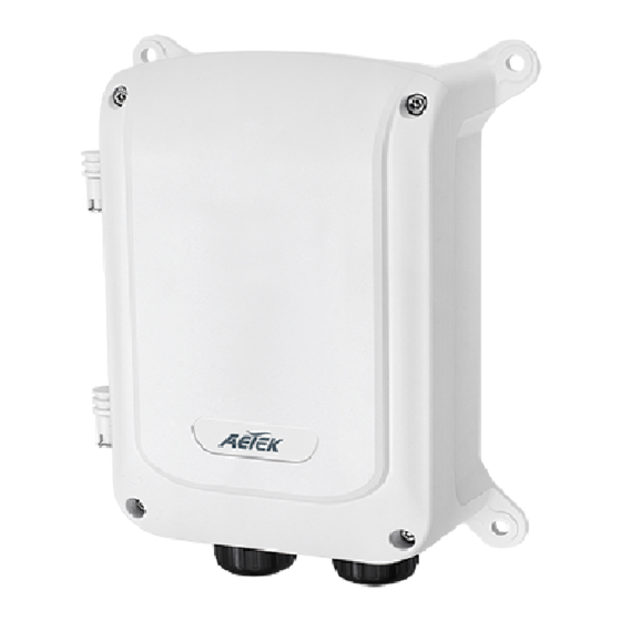
The H21-041-30-075 is a 4 port 10/100BaseT PoE switch capable of feeding 15.4/30W (54V max. per port) power to
Power over Ethernet (PoE) devices. It comes with another 1x FE RJ45 uplink port.
PACKAGE CONTENTS
* 1x PoE switch
* 1x T25 L-wrench
IMPORTANT:
1. Install the PoE switch in a ventilated and dry place that is free of electromagnetic source, vibration, moisture, and dust.
2. Make sure the ventilation openings on the switch are not blocked.
3. Use CAT5 or 5e UTP/STP cables.
4. AC input (100~240V/AC, 50~60Hz)
5. IP67 rated housing
6. Although housing is IP67 rating , this is not suitable for water jets.
CONNECTION
Industrial 4xFE PoE + 1xFE
EXPoE Switch
1
+ -
LINK/ACT
PoE
100-240VAC
VAC 100~240 power input
EX MODE DIP SWITCH
EX ON
Ports 1 & 2 up to 250m PoE distance. When enabled, each port is isolated, but is linked to the uplink ports.
EX OFF
Normal communication for ports 1 ~ 5.
* EX mode in 802.3af (15.4W): camera connection up to 250m@10Mbps via EXPoE ports.
* EX mode in 802.3at (30W): camera connection up to 200m@10Mbps via EXPoE ports.
*Effect factors
1.Must connect af PoE PD.
2.Poor cabling quality with insufficient copper.
3.IP camera's networking design could not support 10Mbps@250m transmission.
**Suggestion
1.Checking the interoperability reaching 10Mbps@250m before physical deployment.
2.Adjust to "EX Mode OFF" reaching 10/100Mbps@100m if "EX Mode ON" is fail.
LED DEFINITIONS
Power
Orange ON
Orange Off
Link/Act
Green ON
Green Off
Green blinking
PoE
Orange ON
Orange Off
Orange blinking
H21-041-30-075
Quick Installation Guide
* 1x Quick Installation Guide
2
3
4
5
EX Mode
OFF
ON
PWR
Power is on and normal.
Power is off.
Ethernet port is connected.
No connection.
Data is being transmitted or received.
Port is linked to a powered device.
No device is connected.
Abnormal power supply is detected.
Outdoor Unmanaged PoE Switch
Port LED1
Port LED2
Advertisement
Table of Contents

Related Manuals for AETEK H21-041-30-075


Summary of Contents for AETEK H21-041-30-075
- Page 1 Outdoor Unmanaged PoE Switch Quick Installation Guide INTRODUCTION The H21-041-30-075 is a 4 port 10/100BaseT PoE switch capable of feeding 15.4/30W (54V max. per port) power to Power over Ethernet (PoE) devices. It comes with another 1x FE RJ45 uplink port. PACKAGE CONTENTS...
- Page 2 2. The cabinet must be grounded using a ground wire between the ground screw and earth ground. All specifications are subject to change without noice. Copyright © 2017 AETEK INC. All rights reserved. AETEK INC. 3F, No.192, Lien-Cheng Rd., Chung-Ho, New Taipei City, 235, Taiwan, R.O.C.
Need help?
Do you have a question about the H21-041-30-075 and is the answer not in the manual?
Questions and answers