
Related Manuals for Vanco Evolution EVWP2006


Summary of Contents for Vanco Evolution EVWP2006
- Page 1 HDMI® E X TE N DER Wall Plate over single Cat5e/Cat6 Cable with POE Vanco Part Number: EVWP2006 HDMI® Wall Plate Extender over Single Category 5e/6 Cable with POE www.vanco1.com • 800.626.6445...
- Page 2 DEAR CUSTOMER Thank you for purchasing this product. For optimum performance and safety, please read these instructions carefully before connecting, operating or adjusting this product. Please keep this manual for future reference. This product is 100% inspected and tested in the United States to verify HDMI performance parameters.
- Page 3 INTRODUCTION The Evolution by Vanco EVWP2006 HDMI Wall Plate Extender over Single Cat5e/6 with Bi-directional IR, auto EDID/EQ, and PoE extends high definition video and audio signals, IR, and power at a distance of up to 164ft/50m over a single Cat5e/6 cable.
-
Page 4: Specifications
SPECIFICATIONS TECHNICAL SPECS Transmitter ............... HDMI input, IR output (3.5mm), IR input (3.5mm),RJ45 Ethernet interface, 12V DC in Receiver ..............HDMI output, IR output (3.5mm), IR input (3.5mm),RJ45 Ethernet interface, 12V DC in Power ............... <3.5W TX or <2.5W RX Dimension .............. -
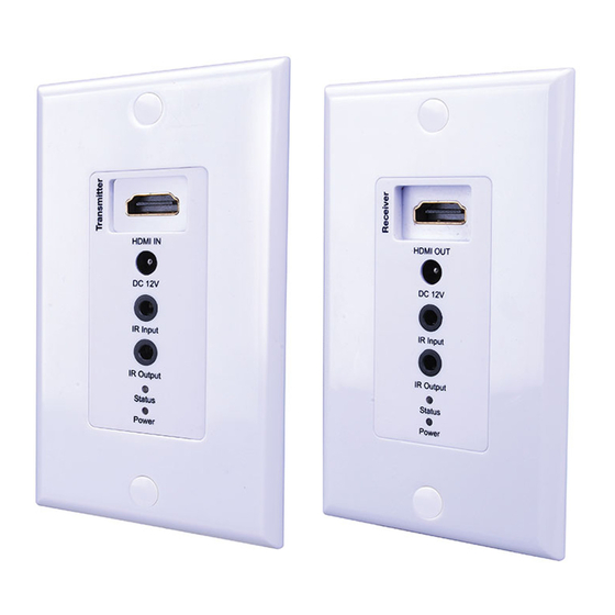
Page 5: Panel Descriptions
PANEL DESCRIPTIONS Back Transmitting Unit Receiving Unit Transmitting Unit Receiving Unit 1. HDMI Input port (source) 1. HDMI Output port (display) 2. DC 12V input 2. DC 12V input 3. IR receiver input 3. IR receiver input 4. IR blaster output 4. -
Page 6: Connection Diagram
CONNECTION DIAGRAM HDTV HDMI BEFORE INSTALLATION: IR RX Prepare place for installing system. The video sources should be close to the transmitter, and the displays should be IR TX close to receiver. It is better to keep the HDMI cables less than 6 meters. Terminate the CAT5e/6 cables for connecting the transmitter and the receiver to the 568B standard. - Page 7 IR PASS-THROUGH The bi-directional IR system allows you to control the source that is connected to the extender unit, from the display; or the display from the source, not simultaneously. There are two important things to note when setting up the IR system: 1.
- Page 8 IR RECEIVER (RX) • To control the source: Plug IR Receiver into IR Input port of receiver unit (EVWP2006-RX); place receiver at or near display. • To control the display: Plug IR Receiver into IR Input port of transmitter unit (EVWP2006-TX); place receiver in position where it is able to receive remote signals.
- Page 9 NOTICE 1. Vanco HDMI and Cat5e/6 cables are strongly recommended for use with this product to ensure best results. 2. Incorrect placement of IR Blaster and Receiver may result in the failure of the IR extenders. Please check carefully before plugging in the IR extender to the respective IR sockets.
-
Page 10: Troubleshooting
4. If you are still encountering issues, attempt the “hot-plug concept. With all of the HDMI cables disconnected, turn on the source and plug in the HDMI cable into it’s output, then power up the Vanco unit and plug the HDMI cable into it’s input, finally turn on the display and plug the HDMI cable from the receiver into it. -
Page 11: Limited Warranty
If repairs are needed during the warranty period the purchaser will be required to provide a sales receipt/sales invoice or other acceptable proof of purchase to the seller of this equipment. The seller will then contact Vanco regarding warranty repair or replacement. - Page 12 ® Vanco International 506 Kingsland Drive Batavia, Illinois 60510 call: 800.626.6445 fax: 630.879.9189 visit: www.vanco1.com...
Need help?
Do you have a question about the Evolution EVWP2006 and is the answer not in the manual?
Questions and answers