
Subscribe to Our Youtube Channel
Related Manuals for GeoVision GV-IP Series


Summary of Contents for GeoVision GV-IP Series
- Page 1 Quick Start Guide GV-IP Thermal Camera Before attempting to connect or operate this product, TMEB-QG-A please read these instructions carefully and save this manual for future use.
- Page 2 GeoVision. Every effort has been made to ensure that the information in this manual is accurate. GeoVision, Inc. makes no expressed or implied warranty of any kind and assumes no responsibility for errors or omissions. No liability is assumed for incidental or consequential damages arising from the use of the information or products contained herein.
- Page 3 Warning and Caution Please read this instruction carefully before operating the unit and keep it for further reference. All the examples and pictures used here are for reference only. The contents of this manual are subject to change without notice. ...
-
Page 4: Table Of Contents
Contents 1. Overview ......................1 2. Installation ......................3 3. Accessing the Network Camera ................6 3.1 Looking Up the Dynamic IP Address ..............6 3.2 Configuring the IP Address ................8 4. The Web Interface ....................9 5. Upgrading System Firmware ................10 6. Restoring to Factory Default................11 ... -
Page 5: Overview
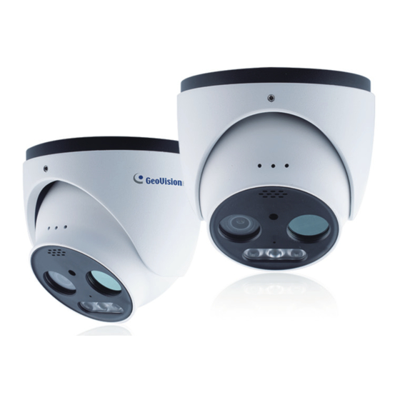
1. Overview Ethernet connector Audio input connector (3.5mm) Alarm input/output Power connector Speaker Thermal lens Light sensor Optical lens Microphone 10. Flashing light 11. IR LED 12. Micro SD card slot 13. Load Default Note: The camera can be powered by DC 12V / PoE power supply. If the PoE switch is used to power the camera, DC12V power supply is not required. -
Page 7: Installation
2. Installation Please make sure that the wall or ceiling is strong enough to withstand 3 times the weight of the camera. And install and use the camera in the dry environment. Loosen the fixed screw to disassemble the camera. 2. - Page 8 Loosen the nut from the main element. Run the network cable (without RJ 45 connector) through the both elements. Then crimp the cable with RJ 45 connector. Connect the cable to the hermetic connector. Then tighten the nut and the main cover. Secure the mounting base to the ceiling or wall with the screws provided.
- Page 9 Fix the camera with the fixed screw.
-
Page 10: Accessing The Network Camera
3. Accessing the Network Camera Looking Up the Dynamic IP Address By default, when the camera is connected to a LAN with the DHCP server, it is automatically assigned with a dynamic IP address. Follow the steps below to look up its IP address. - Page 11 5. Type a new password and click OK. 6. Click on its IP address again and select Webpage to open its Web interface. 7. Type the set password on the login page and click Login. IMPORTANT: 1. The camera has two sets of passwords: one is for Web interface and the other is for the third-party platform connection via ONVIF, e.g.
-
Page 12: Configuring The Ip Address
Configuring the IP Address If the camera is connected to a LAN without the DHCP server, the default IP address will be 192.168.0.10. Follow the steps below to modify the IP address to avoid IP conflict with other GV-IP devices on the same LAN. 1. -
Page 13: The Web Interface
4. The Web Interface Once you log in the Web interface, you will see the live view as shown below. IMPORTANT: It is required to use IE or Edge IE mode to access thermal images. Icon Description Icon Description Visible light image and Fire detection indicator thermal image display Visible light image display... -
Page 14: Upgrading System Firmware
5. Upgrading System Firmware GeoVision periodically releases updated firmware on the company website. To load the new firmware into the camera, follow the instructions below. 1. On the Web interface, click Config > Maintenance > Upgrade. 2. Click the Browse button to locate the firmware file saved at your local computer. -
Page 15: Restoring To Factory Default
6. Restoring to Factory Default If for any reason the camera is not responding correctly, you can restore the camera back to its factory default settings using the Web interface or the Load Default Button. On the Camera 1. Find the Load Default button on the camera (see No. 13, 1. Overview in the Quick Start Guide). -
Page 16: Connecting To Gv-Vms
7. Connecting to GV-VMS To connect GV-TMEB5800 to GV-VMS surveillance system, follow the steps below. Note: The integration with GV-VMS is coming soon. Make sure to use the camera’s ONVIF password to connect to GV-VMS. The camera allows for a maximum of 10 simultaneous connections, including the Web, ONVIF and RTSP.
Need help?
Do you have a question about the GV-IP Series and is the answer not in the manual?
Questions and answers