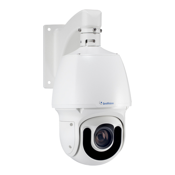
GeoVision GV-SD2322-IR Quick Start Manual
Speed dome
Hide thumbs
Also See for GV-SD2322-IR:
- User manual (108 pages) ,
- Quick start manual (28 pages) ,
- Quick start manual (26 pages)
Table of Contents
Advertisement
Quick Links
Download this manual
See also:
User Manual
Advertisement
Table of Contents

Subscribe to Our Youtube Channel
Related Manuals for GeoVision GV-SD2322-IR


Summary of Contents for GeoVision GV-SD2322-IR
-
Page 1: Quick Start Guide
Quick Start Guide GV-SD2322-IR Speed Dome Before attempting to connect or operate this product, ISD2322IR-QG-A please read these instructions carefully and save this manual for future use. - Page 2 Every effort has been made to ensure that the information in this manual is accurate. GeoVision, Inc. makes no expressed or implied warranty of any kind and assumes no responsibility for errors or omissions. No liability is assumed for incidental or consequential damages arising from the use of the information or products contained herein.
-
Page 3: Table Of Contents
Contents Note for Connecting to GV-VMS / DVR / NVR........ii Note for Recording................iii Note for Installing Camera Outdoor............iv 1. Introduction ..................1 1.1 Packing List ......................1 1.2 Optional Accessories ..................... 2 1.3 Overview........................ 2 2. Installation ..................3 3. Connecting the Camera ..............6 4. -
Page 4: Note For Connecting To Gv-Vms / Dvr / Nvr
Note for Connecting to GV-VMS / DVR / NVR The GV-IP Speed Dome is designed to work with GV-VMS / DVR / NVR, a video management system. Note the following when the camera is connected to GV-VMS / DVR / NVR: 1. -
Page 5: Note For Recording
Note for Recording 1. Mind the following when using a memory card for recording: • Recorded data on the memory card can be damaged or lost if the data are accessed while the camera is under physical shock, power interruption, memory card detachment or when the memory card reaches the end of its lifespan. -
Page 6: Note For Installing Camera Outdoor
Note for Installing Camera Outdoor When installing the camera outdoor, be sure that: The camera is set up above the junction box to prevent water from entering the camera along the cables. Any power, audio and I/O cables are waterproofed using waterproof silicon rubber or the like. -
Page 7: Introduction
Introduction 1. Introduction Welcome to the GV-SD2322-IR Speed Dome Quick Start Guide. In the following sections, you will learn the basic installations and configurations. For a detailed user manual, see the GV-SD2322-IR Speed Dome User’s Manual on the Software DVD. -
Page 8: Optional Accessories
1.2 Optional Accessories Optional devices can expand the capabilities and versatility of your camera. Contact your dealer for more information. Name Details GV-Mount Accessories The GV-Mount Accessories provides a comprehensive lineup of accessories for installation on ceiling, wall and pole. For details, see GV-Mount Accessories Installation Guide on the software DVD. -
Page 9: Installation
Installation 2. Installation You can separately purchase optional mounting accessories to mount GV-SD2322-IR on a wall, ceiling or pole. Make sure the wall has enough strength to support the camera and the mount. For details, see GV-Mount Accessories Installation Guide. - Page 10 Place the pendant tube on the wall, and mark the position of the screw holes. Drill holes on the wall, and secure the pendant tube to the wall with 4 self-prepared screws. Attach the safety lock of the camera to the pendant tube. Thread the data cable through the pendant tube.
- Page 11 Installation Attach the camera to the pendant tube, rotate the camera until it is locked into position, and secure the indicated screws. Insert the pendant mount screws and tighten with the supplied M4 hex key. Thread the Ethernet cable through the waterproof rubber set as shown below. Note: The size of RJ-45 connector must be within 14 mm to go through the waterproof rubber set.
-
Page 12: Connecting The Camera
3. Connecting the Camera The camera comes with a data cable that allows you to connect the camera to the power adapter, microphone, speaker, and I/O devices. Connect the supplied power adapter to the 3-pin terminal block. Either of the red and black cables can be used for anode (+) and the cathode (-). - Page 13 Connecting the Camera Wire Definition No. Wire Definition Brown Audio in Brown / White Green Audio out Green / White Gray Alarm IN 1 Purple Alarm IN 2 Black Orange Alarm In - Orange / White Alarm Out + Yellow RS-485 –...
-
Page 14: Accessing The Camera
4. Accessing the Camera 4.1 Web Browser Once installed, your camera is accessible over the network. Make sure your PC has good network connection, and meet the following requirement. Dual-Core, 2.0 GHz or higher Memory At least 1 GB Graphic Card At least 128 MB display memory Web Browsers Internet Explorer 11.0 or above... -
Page 15: Looking Up The Dynamic Ip Address
Accessing the Camera 4.2 Looking Up the Dynamic IP Address By default, when the camera is connected to LAN with a DHCP server, it is automatically assigned with a dynamic IP address. Follow the steps below to look up its IP address. Note: The computer you use to configure the IP address must be under the same LAN with your camera. - Page 16 4. The login page appears. 5. Type the default ID and password admin and click Apply to log in.
-
Page 17: Configuring The Ip Address
Accessing the Camera 4.3 Configuring the IP Address If the camera is connected to LAN without a DHCP server, the default IP address will be 192.168.0.10. Follow the steps below to modify the IP address to avoid IP conflict with other GV-IP devices on the same LAN. -
Page 18: The Web Interface
5. The Web Interface Once you log in the Web interface, you will see the live view as shown below. No. Name Function Set the display ratio of the image. • Scale: display images by 16:9. Proportional • Stretch: display images by window size. •... - Page 19 The Web Interface Adjust the audio output volume on the PC. Volume Adjust the microphone volume on the PC during audio Microphone communication between the PC and the camera. Snapshot Take a snapshot of the current image displayed on the PC. Local Recording Start or stop...
-
Page 20: Ptz Control Panel
5.1 PTZ Control Panel You can find the PTZ control panel to the right of the live view. No. Item Function 1 Auto Pan Start or stop auto panning of the camera. 2 PTZ Control Panel Control the direction of the camera and release the control. 3 PTZ Speed Adjust the moving speed of the PTZ camera. - Page 21 The Web Interface Adding a Preset Point 1. On the Live View page, click Preset on the control panel. 2. Adjust the camera until it points toward the desired direction. 3. Adjust zoom and focus as needed to obtain the optimal image. 4.
- Page 22 Adding a Patrol Route 1. On the Live View page, click Patrol on the control panel. 2. Click the Add button to add a patrol route. 3. On the Add Patrol page, enter the route ID and name. 4. Click Add to add a patrol action. Use the buttons to adjust the sequence of the actions. Note: Patrol actions include It is recommended that the first action type is Go to Preset.
-
Page 23: Upgrading System Firmware
Upgrading System Firmware 6. Upgrading System Firmware GeoVision periodically releases the updated firmware on the website. To load the new firmware into the camera, follow the instructions below. 1. In the Live View window, click the Show System Menu button and select Remote Config. At the top, click Setup. -
Page 24: Restoring To Factory Default
7. Restoring to Factory Default You can restore the camera to factory default settings using the Web interface or directly on the camera. 7.1 Using the Web Interface To restore to default settings using the Web interface: 1. At the top, click Setup. 2. -
Page 25: Directly On The Camera
Restoring to Factory Default 7.2 Directly on the Camera 1. Unscrew the back cover of the camera. 2. Press and hold the default button for about 30 seconds. 3. When the camera rotates twice, the process of loading default is completed and the camera robots automatically.
Need help?
Do you have a question about the GV-SD2322-IR and is the answer not in the manual?
Questions and answers