Table of Contents
Advertisement
Quick Links
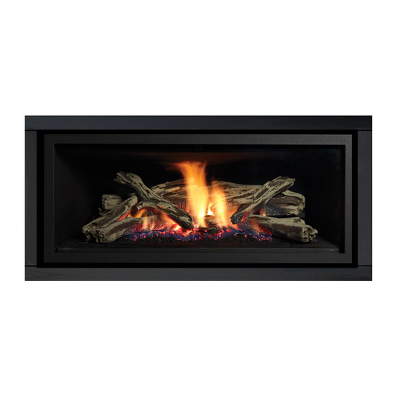
Greenfire
Gas Fireplace
www.regency-fire.com.au
WARNING:
If the information in these instructions are not followed exactly,
a fire or explosion may result causing property damage,
personal injury or loss of life.
FOR YOUR SAFETY
Do not store or use petrol or other flammable vapors and
liquids in the vicinity of this or any other appliance.
Installation and service must be performed by a qualified
installer, service agency or the gas supplier.
919-501f
GF900L
®
Installer: Please complete the details on the back cover
and leave this manual with the homeowner.
Homeowner: Please keep these instructions for future reference.
Owners &
Installation Manual
MODELS: GF900L-NG1
GF900L-LP1
GF900L-ULPG1
GF900L Video
LISTINGS AND CODE APPROVALS
These gas appliances have been tested
in accordance with AS4553 / NZS5262 /
NZS5266 and have been certified by the
Australian Gas Association for installation and
operation as described in these Installation
and Operating Instructions.
Must be installed as per AS/NZS5601-2013
Your unit should be serviced annually by
an authorised service person.
FOR YOUR SAFETY
What to do if you smell gas:
Do not try to light any appliance.
Do not touch any electrical switch.
Do not use any phone in your
building.
Immediately call your gas supplier
from a neighbour's phone. Follow
the gas supplier's instructions.
If you cannot reach your gas
supplier, call the fire department.
21 March 2019
Advertisement
Table of Contents

Subscribe to Our Youtube Channel
Related Manuals for Regency Fireplace Products Greenfire GF900L


Summary of Contents for Regency Fireplace Products Greenfire GF900L
- Page 1 Greenfire GF900L ® Owners & Gas Fireplace Installation Manual MODELS: GF900L-NG1 GF900L-LP1 GF900L-ULPG1 GF900L Video LISTINGS AND CODE APPROVALS These gas appliances have been tested in accordance with AS4553 / NZS5262 / NZS5266 and have been certified by the Australian Gas Association for installation and operation as described in these Installation and Operating Instructions.
-
Page 2: Pairing The Remote Handset And Control Box Id Code
To the New Owner: Congratulations! You are the owner of a state-of-the-art Gas Fireplace by REGENCY . The GF900L has been designed to provide you ® with all the warmth and charm of a wood fireplace at the flick of a switch. The model GF900L has been approved by AGA for both safety and efficiency. -
Page 3: Table Of Contents
table of contents Gas Line Installation ............29 Pairing the Remote Handset and Control Box ID Code .2 Copy of data badge ............4 Pilot Adjustment ............29 Unit Dimensions ............5 Gas Pipe Pressure Testing ..........29 Verona Surround Faceplate Dimensions .......5 Wiring Diagram ............30 Conversion from NG to LP/ULPG ........31 Important Message ............6 General Safety Information ..........6... -
Page 4: Copy Of Data Badge
SAFETY LABEL safety decal This is a copy of the data badge that accompanies each GF900L Direct Vent Gas Fireplace. We have printed a copy of the contents here for your review. NOTE: Regency ® units are constantly being improved. Check the badge on the unit and if there is a difference, the badge on the unit is the correct one. COPY OF DATA BADGE Regency Gas Fireplace Distributed by:... -
Page 5: Unit Dimensions
dimensions DIMENSIONS UNIT DIMENSIONS (76mm) (259mm) (500mm) (560mm) (14mm) (1091mm) (522mm) (995mm) (1082mm) (889mm) (795mm) (536mm) (332mm) (725mm) (160mm) (113mm) (1192mm) (989mm) Verona Surround Faceplate Dimensions Regency GF900L-1 Gas Fireplace... -
Page 6: Important Message
installation IMPORTANT MESSAGE YOUNG CHILDREN SHOULD BE 11) Under no circumstances should this appliance SAVE THESE be modified. Parts that have to be removed CAREFULLY SUPERVISED WHEN for servicing should be replaced prior to THEY ARE IN THE SAME AREA AS INSTRUCTIONS operating this appliance. -
Page 7: Installation Checklist
installation INSTALLATION CHECKLIST This includes: 4) The GF900L Direct Vent Gas Fireplace is approved for alcove installations, see 1) Clocking the appliance to ensure the correct "Clearances" section for details. 1) Locate appliance firing rate (rate noted on label) after burning a) Room location (Refer to "Locating Your appliance for 15 minutes. -
Page 8: Clearances
installation CLEARANCES The clearances listed below are Minimum distances unless otherwise stated: A major cause of chimney related fires is failure to maintain required clearances (air space) to combustible materials. It is of the greatest importance that this fireplace and vent system be installed only in accordance with these instructions. Caution Requirements WARNING Fire hazard is an extreme risk... -
Page 9: Mantel Clearances
installation MANTEL CLEARANCES Due to the extreme heat this fireplace emits, the mantel clearances (305mm) (152mm) are critical. Combustible mantel clearances from top of front facing are shown in the diagram on the right. (660mm) (305mm) Combustible Material Note: Ensure the paint that is used on the mantel and the facing is "high quality"... -
Page 10: Unit Assembly Prior To Installation
installation UNIT ASSEMBLY PRIOR TO INSTALLATION The nailing strips must be correctly positioned and attached before unit is slid into position. NAILING STRIPS The nailing strips come attached to the unit. There is 1 plate on each side, 1 on the top. The top and side nailing strips are secured to the framing. -
Page 11: Framing Dimensions
installation FRAMING DIMENSIONS Framing Description GF900 Dimensions Framing Height 1089mm Framing Width 1127mm Framing Depth 552mm Minimum Height to Combustibles 1151mm Corner Wall Depth 1273mm Corner Facing Wall Width 1800mm Vent Centerline Height 991mm Non-combustible facing height 483mm Gas Connection Opening Height 38mm Gas Connection Height 67mm... -
Page 12: Optional Framing Kit
GF900 installation OPTIONAL FRAMING KIT OPTIONAL FRAMING KIT 1. Construct the timber framing, ensure inside dimensions are 1089mm H x 1127mm W as shown below. 1127mm 1089mm (466-126) Flat side out 5. Secure horizontal steel header stud (466-128) with 2 screws per side as 2. -
Page 13: Non Combustible Facing Installation
7) Paint walls using a high quality paint which will withstand the high Discoloration is not the responsibility of Regency Fireplace Products, temperatures being emitted from this appliance. we believe careful attention to the recommendations provided here will be result in aesthetically pleasing result free of issues outlined above. -
Page 14: Framing & Finishing
installation FRAMING & FINISHING 1) Frame in the enclosure for the unit with framing material. 5) If material such as brick, stone, etc extends past the faceplate depth 38mm, when finishing around the faceplate, the minimum opening dimensions IMPORTANT: The framed opening must be of non-combustible noted below must be adhered to ensuring for the removal of the faceplate material. -
Page 15: Combustible Requirements
installation FRAMING & FINISHING Finished Nailing Strip Material Position 12mm 25mm Nailing Strip 25mm Forward Unit 25mm 12mm Note: Nailing Strip • The siding nailing strips are factory set at 12mm. The 12mm Forward top nailing strip is fixed during transit to the rear of the appliance. -
Page 16: Exterior Flue Termination Locations
installation EXTERIOR FLUE TERMINATION LOCATIONS FIGURE 6.2 (in part): LOCATION OF FLUE TERMINALS OF BALANCED FLUE AS/NZ 5601-2013, ROOM-SEALED, FAN ASSISTED OR OUTDOOR APPLIANCE Regency GF900L-1 Gas Fireplace... -
Page 17: Clearances
installation CLEARANCES Minimum clearances (mm) Ref. Item Natural Draught Assisted Below eaves, balconies and other projections: Appliances up to 50 MJ/h input Appliances up to 50 MJ/h input From the ground, above a balcony or other surface* From a return wall or external corner* From a gas meter (M) (see Note 5) (see Clause 5.11, 5.9 for vent terminal location of regulator) 1000... -
Page 18: Flue Restrictor Position
installation FLUE RESTRICTOR POSITION FLUE RESTRICTOR SETTING Flue restriction is required for certain venting installations, see the diagrams in the "Flueing Arrangements" section to determine if they are required for your installation. The Flue Restrictor plate is located on the inside top of the firebox. Set 3 - 18mm open To set the flue restriction as indicated in the flueing arrangements diagrams, refer to the following instructions;... -
Page 19: Flueing Introduction
installation FLUEING INTRODUCTION The GF900L uses the "balanced flue" technology Co-Axial system. The inner liner vents products of combustion to the outside while the outer liner draws outside combustion air into the combustion chamber thereby eliminating the need to use heated room air for combustion and losing warm room air up the chimney. Note: These flue pipes must not be connected to any other appliance. -
Page 20: Flueing Arrangements
installation FLUEING ARRANGEMENTS HORIZONTAL TERMINATION (FLEX) Regency Direct Vent System ® These flueing systems, in combination with GF900L, have been tested and listed as a Direct Vent system by AGA. The location of the termination cap must conform to the requirements in the Flue Terminal Locations diagram from the "Exterior Flue Termination Locations" section. Regency Direct Vent (Flex) System Termination Kits includes all the parts needed to install the GF900L using a flexible vent. -
Page 21: Horizontal Terminations
installation HORIZONTAL TERMINATIONS " ( RIGID PIPE 4" X 6-5/8 102MM X 175MM) The minimum components required for a basic horizontal termination are: Horizontal Termination Cap Elbow Rigid Pipe Adaptor (510-994) Wall Thimble Length of pipe to suit wall thickness (see chart) Horizontal Termination Cap... -
Page 22: Horizontal Terminations
installation HORIZONTAL TERMINATIONS " ( RIGID PIPE 4" X 6-5/8 102MM X 175MM) The diagrams below shows examples of horizontal termination arrangements using one 90 elbow. 1) A maximum of one 90 or two 45 elbows is permitted. 2) Minimum distance between elbows is 305mm. •... -
Page 23: Vertical Terminations
installation VERTICAL TERMINATIONS " ( RIGID PIPE 4" X 6-5/8 102MM X 175MM) The minimum components required for a basic vertical termination using Simpson Duravent Rigid Flue System are: High wind cap Vertical Termination Cap Rigid Pipe Adaptor (510-994) Flashing Storm Collar Length of pipe to suit height requirement (see chart) -
Page 24: Flueing Arrangement For Vertical Terminations
installation FLUEING ARRANGEMENT FOR VERTICAL TERMINATIONS Vertical Venting with One(1) 90 Elbows (1 - 90 2 - 45 Metres The shaded area in the diagram shows all allowable combinations of straight vertical and offset to vertical terminations, using two elbow, with Rigid Pipe Flueing Systems. •... -
Page 25: Direct Flue Zero Clearance Top Exit Vertical Flue Kit Installation Instructions Gf900
installation DIRECT FLUE ZERO CLEARANCE TOP EXIT VERTICAL FLUE KIT INSTALLATION INSTRUCTIONS GF900 This flue kit has been manufactured for use with GF900L and to be installed in accordance with AS/NZS 5601-2013. To ensure safety and correct unit operation this flue kit must be installed as outlined in these instructions. Heater and flue clearances from combustible materials must be in accordance with these instructions and AS/NZS 5601-2013. -
Page 26: Unit Installation With Horizontal Termination
installation UNIT INSTALLATION WITH 5) Assemble the desired combination of pipe and 7) Ensure that the pipe clearances to combustible elbows to the appliance flue outlets and secure. materials are maintained (Diagram 5). Install HORIZONTAL TERMINATION the termination cap. 102MM X 175MM FLUEING (Rigid Flue Systems) Note: If installing termination on a siding Note: For best results and optimum... -
Page 27: Unit Installation With Horizontal Termination
installation ASTROCAP UNIT INSTALLATION WITH 5) Slip the assembled liner and termination DIMENSIONS (946-523/P) HORIZONTAL TERMINATION assembly through the thimble making sure the 102MM X 175MM FLUEING termination cap faces up (there are markings (Flex Flue Systems) on the cap indicating which way is up). This will position the termination cap with proper down Minimum Flue Clearances slope for draining water. -
Page 28: Unit Installation With Vertical Termination
installation UNIT INSTALLATION WITH 4) Cut a hole in the roof centered on the small drilled hole placed in the roof in Step 2. The hole VERTICAL should be of sufficient size to meet the minimum TERMINATION requirements for clearance to combustibles of Flue Height 38mm. -
Page 29: High Elevation
installation PILOT ADJUSTMENT GF900L-NG SYSTEM DATA NOTE: The outlet pressure must be set to maximum 2.49 kPa for both LP/ULPG and 0.87 kPa for NG. Min. Supply Pressure 1.13 kpa Periodically check the pilot flames. Correct flame Low Setting Man. 0.4kpa Minimum pressure: Remove one of the cables co pattern has two strong blue flames: 1 flowing... -
Page 30: Wiring Diagram
installation WIRING DIAGRAM DISCONNECT POWER SUPPLY TO UNIT PRIOR TO WORKING ON ELECTRICAL COMPONENTS. ORANGE BLUE MODULATING VALVE GREEN ORANGE COIL PRESSURE SWITCH SPARKER BROWN SIGMA 845 (NO) MODULE - SPARK PILOT FLAME MODULE - FLAME SENSOR SIT 201 IGNITION MODULE MODULE - EARTH GREEN BLACK... -
Page 31: Conversion From Ng To Lp/Ulpg
installation GF900 CONVERSION KIT #466-967 FROM NG TO LP/ULPG CONVERSION KIT #466-967 FROM NG TO ULPG FOR GF900L USING SIT 845 NOVA GAS VALVE FOR GF900 USING SIT 845 NOVA GAS VALVE THIS CONVERSION MUST BE DONE BY A QUALIFIED GAS FITTER IF IN DOUBT DO NOT DO THIS CONVERSION !! Each Kit contains one LP / ULPG 4. - Page 32 GF900 installation 8. Remove burner by removing 2 screws at the back of the burner in 12. Reinstall new burner orifi ce LP stamped #53 or ULPG burner locations shown below. orifi ce stamped #53 and tighten. 13. Replace the yellow "NG" label with the red "ULPG" label. 14.
-
Page 33: I.t. Valve Description
GF900 installation 845 S.I.T. VALVE DESCRIPTION 21. Adjusting the Outlet Pressure All the adjustments must be carried out in the following order: 1) On-Off Solenoid Valve EV1 2) On-Off Solenoid Valve EV2 Remove the modulator plastic cap (A) using needle nose pliers. 3) Inlet Pressure Test Point Maximum pressure: Turn the unit ON to its highest input 4) Outlet Pressure Test Point... -
Page 34: Optional Fan Ducting Kit Installation
installation GF900 OPTIONAL FAN DUCTING KIT INSTALLATION OPTIONAL FAN DUCTING KIT INSTALLATION LISTINGS AND CODE GENERAL INFORMATION Maximum Duct Run: 9.0m Kit Contains 4.5m APPROVALS The Fan Kit increases the eff ectiveness of your fi replace by dispersing warm air from the fi replace If you require more than 4.5m please purchase Fan This Fan Kit has been approved for use with GF900. -
Page 35: Optional Fan Kit Installation
installation GF900 OPTIONAL FAN KIT INSTALLATION OPTIONAL FAN KIT INSTALLATION NOTE: Installation of Fan Kit should be done prior Air Duct to installation of the wall. 2. Mount and secure the fan housing assembly to framing members, the front of the fan housing will protrude 12.7mm out of the wall so it may be fi... -
Page 36: Fan Duct Extension Kit Installation
GF900 installation OPTIONAL FAN KIT INSTALLATION FAN DUCT EXTENSION KIT INSTALLATION FAN DUCT EXTENSION KIT In order to use the fan extension duct kit, you must have fan kit. This kit allows you to extend the fan duct to 9m. 1. -
Page 37: Log Set Installation
gF900 installation LOG SET INSTALLATION Log Set InStaLLatIon Read the instructions below carefully and refer to the images. If the logs are broken do not use the unit until they are replaced. Broken logs can interfere with pilot operation. Improper positioning of the logs may create carbon build-up and can alter the unit's performance which is not covered under warranty. - Page 38 GF900 installation 7. Position Log 6 to rest on Log 1 and Log 3 as shown in Diagram 9. 4. Rest Log 4 on Log 1 and Ceramic Log Burner as shown in Diagram 6. Diagram 9 Diagram 6 8. Line up locator on bottom of Log 7 with locator on Ceramic Log Burner as shown in Diagram 10.
-
Page 39: Front Trim Removal / Installation
installation FRONT TRIM REMOVAL / INSTALLATION 1. Remove faceplate, inner door frame, and glass door if already installed - see instructions in this manual. 2. Remove two (2) screws in locations shown below to remove front trim piece. 3. Reverse steps to reinstall. Front Trim Piece Diagram 1 - Front Trim Screw Locations INNER PANEL REMOVAL / INSTALLATION... -
Page 40: Faceplate And Deflector Installation
GF900 installation FACEPLATE AND DEFLECTOR INSTALLATION FACEPLATE AND DEFLECTOR INSTALLATION 4 screws 1. Install the fascia to the unit by hooking the left and right side mounting brackets into the mounting slots at the side ofthe firebox as shown below. Diagram 4 3 Mounting Slots Diagram 1... -
Page 41: Screen & Inner Door Frame Installation
GF900 installation SCREEN & INNER DOOR FRAME INSTALLATION SCREEN & INNER DOOR FRAME INSTALLATION 1. Hang Screen Mesh over Inner Door Frame as shown in Diagram 1. 3. Install Screen and Inner Door Frame to unit over glass door frame as shown in Diagram 3. -
Page 42: Optional Finishing Trim Installation
installation GF900 GLASS SURROUND INSTALLATION Install the fascia to the unit by hooking the left and right side mounting brackets into the mounting slots at the side of the fi rebox as shown below. It is recommended that you use the fi rst mounting slot (the one closest to the door frame overlay) out of the 3 so that the faceplate and door frame overlay are fl... -
Page 43: Operating Instructions
operating instructions FIRST FIRE SUMMARY OF OPERATING CONTROLS INSTRUCTIONS The FIRST FIRE in your heater is part of the paint curing process. To ensure that the paint On/Off Button Before operating this appliance, proceed through is properly cured, it is recommended that you If the unit is switched off, pressing and releasing the following check list. -
Page 44: Copy Of Lighting Plate Instructions
operating instructions COPY OF LIGHTING PLATE INSTRUCTIONS RESETTING THE UNIT NORMAL OPERATING FOR YOUR SAFETY READ BEFORE LIGHTING SOUNDS OF If the appliance goes to 'lockout', the system GAS APPLIANCES This appliance must be installed in accordance will have to be reset by depressing the reset with the current AS/NZS 5601-2013 WARNING: If you do not follow these button - located on the right side of the unit... -
Page 45: Fan Service
maintenance FAN SERVICE PRIOR TO SERVICING THE FAN, ENSURE UNIT HAS COOLED TO 6. Remove access panel by removing eight(8) screws in locations ROOM TEMPERATURE, ALL POWER IS DISCONNECTED AND GAS shown in Diagram 4. SUPPLY IS TURNED OFF. 1. Remove faceplate, inner frame, glass door, front trim piece and inner panels - see instructions in this manual. -
Page 46: Maintenance Instructions
maintenance MAINTENANCE GENERAL FLUE GLASS GASKET INSTRUCTIONS MAINTENANCE If the glass gasket requires replacement use a Conduct an inspection of the venting system 1) Always turn off the gas valve before cleaning. tadpole glass gasket (Part # 936-157). semi-annually. Recommended areas to inspect For relighting, refer to lighting instructions. -
Page 47: Troubleshooting
maintenance TROUBLESHOOTING All maintenance must be carried out by a licensed qualified service person IT IS CRITICAL THAT THIS APPLIANCE IS EARTHED AND THAT THE ACTIVE AND NEUTRAL ARE NOT REVERSED UNIT OPERATION ACTION REQUIRED No gas to the burner The gas valve should open at the same time the ignition commences sparking. -
Page 48: Glass Door Installation
maintenance GLASS DOOR INSTALLATION WARNING: Do not operate the appliance with the glass panels removed, cracked or broken. Replacement of the glass panels should be done by a licensed or qualified service person. Glass should be cool if cleaning is necessary. 1. -
Page 49: Valve Tray Replacement
maintenance VALVE TRAY REPLACEMENT 6. Remove burner by removing 14 screws in locations shown below. PRIOR TO VALVE TRAY REPLACEMENT, ENSURE UNIT HAS COOLED TO ROOM TEMPERATURE, ALL POWER IS DISCONNECTED AND GAS SUPPLY IS TURNED OFF. 1. Remove faceplate, inner frame, glass door, front trim piece and inner panels - see instructions in this manual. -
Page 50: Electronic Components Parts List
parts list PARTS LIST ELECTRONIC COMPONENTS PARTS LIST Note: Depending on the model, the diagram below may not be exactly as shown - for reference purposes only. 910-936 910-082 910-089 910-088 910-912 910-084 910-101 910-526 910-080 911-183 910-514 910-083 910-521, 910-522, 910-523 911-121 FG38 FG39... -
Page 51: Main Assembly
parts list PARTS LIST MAIN ASSEMBLY Part # Description Part # Description 904-644 Orifice - NG #35 396-037 Bottom Door Latch 904-345 Orifice - LP #53 466-576/P GF-900 Valve Assy LP 910-080 Sigma Valve NG 466-574/P GF-900 Valve Assy NG 910-081 Sigma Valve LP 466-044... - Page 52 parts list PARTS LIST MAIN ASSEMBLY Regency GF900L-1 Gas Fireplace...
-
Page 53: Accessories
parts list PARTS LIST ACCESSORIES Part # Description 32 467-922 Inner door frame - Black w/ Screen 467-932 Inner door frame - Stainless w/ Screen 33 467-544 Door Frame Overlay - Black 34 467-938 Fascia and Door Frame Black w/Screen 467-936 Fascia and Door Frame Stainless Steel w/Screen 467-951... -
Page 54: Warranty
WARRANTY warranty Limited Lifetime Warranty FPI Fireplace Products International Ltd. (“the manufacturer”) through its wholly owned subsidiary, Fireplace Products Australia Pty Ltd (for Australia and New Zealand customers) and sold under the Regency® brand of fireplace products (collectively referred to herein as “FPI”), extends this Limited Lifetime Warranty to the original purchaser of this appliance provided the product remains in the original place of installation. - Page 55 WARRANTY warranty part is returned to the distributor, dealer or agent for inspection if requested by FPI. Alternatively, FPI may at its own discretion fully discharge all of its obligations under the warranty by refunding the verified purchase price of the product to the original purchaser.
- Page 56 WARRANTY warranty FPI has no obligation to enhance or modify any unit once manufactured (i.e. as products evolve, field modifications or upgrades will not be performed on existing appliances). Any unit showing signs of neglect or misuse will not be covered under the terms of this warranty policy and may void this warranty.
- Page 57 WARRANTY warranty Limitations of Liability: 1. Exclusion of implied terms The customer may have the benefit of consumer guarantees under the Australian Consumer Law. To the maximum extent permitted by law, all terms, conditions or warranties that would be implied into this Warranty or in connection with the supply of any goods or services by the supplier under law or statute or custom or international conventions are excluded.
- Page 58 WARRANTY warranty How to Obtain Warranty Service: Customers should contact the authorised selling dealer to obtain warranty service. In the event the authorised selling dealer is unable to provide warranty service, please contact FPI by mail at the address listed below. Please include your name, address, purchase date, selling dealer, serial #, type of unit, a brief description of the problem, email and telephone contact information, and a copy of your original tax invoice.
- Page 59 WARRANTY warranty Product Registration and Customer Support: Thank you for choosing a Regency Fireplace. Regency strives to be a world leader in the design, manufacture, and marketing of hearth products. To provide the best support for your product, we request that you complete a product registration form found on our Web Site under Customer Care within ninety (90) days of purchase.
- Page 60 Regency GF900L-1 Gas Fireplace...
- Page 61 NOTES notes Regency GF900L-1 Gas Fireplace...
- Page 62 notes NOTES Regency GF900L-1 Gas Fireplace...
- Page 63 Regency GF900L-1 Gas Fireplace...
- Page 64 Installer: Please complete the following information Dealer Name & Address: ______________________________________________ ___________________________________________________________________ Installer: ___________________________________________________________ Phone #: ___________________________________________________________ Date Installed: ______________________________________________________ Serial No.: __________________________________________________________ Regency and Greenfire are registered trademarks of FPI Fireplace Products International Ltd. GF900L Video © Copyright 2019, FPI Fireplace Products International Ltd. All rights reserved.
Need help?
Do you have a question about the Greenfire GF900L and is the answer not in the manual?
Questions and answers