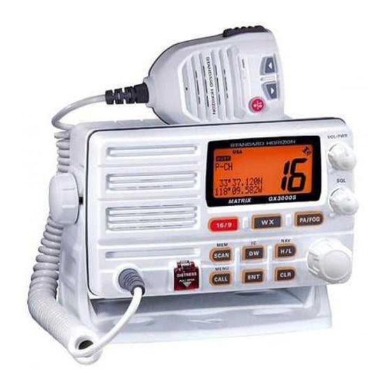
Standard Horizon MATRIX GX3000S Service Manual
25 watt vhf/fm marine transceiver
Hide thumbs
Also See for MATRIX GX3000S:
- Owner's manual (100 pages) ,
- Service manual (66 pages) ,
- Owner's manual (100 pages)
Table of Contents
Advertisement
Quick Links
Advertisement
Table of Contents

Related Manuals for Standard Horizon MATRIX GX3000S


Summary of Contents for Standard Horizon MATRIX GX3000S
- Page 1 25 Watt VHF/FM Marine Transceiver MATRIX GX3000S SERVICE MANUAL EM014N90A...
-
Page 2: Specifications
Specifications GENERAL Channels: All USA, International, and Canadian Input Voltage: 13.8 VDC ±20% Current Drain: Standby 0.5 A Receive 1.5 A Transmit 5.5 A (Hi); 1.5 A (Lo) Dimensions (H x W x D): 4.3” x 7.1” x 4.5” (110 x 180 x 115 mm) Flush-Mount Dimensions (H x W x D): 3.6”... - Page 3 Exploded View & Miscellaneous Parts RA0772900 (WHITE) RA0773000 (BLACK) SLEEVE RA0747100 (WHITE) RA0765100 (BLACK) T9207287 HOOK WIRE ASSY RA0745700 (WHITE) RA0751700 RA0745800 (BLACK) RUBBER PACKING (REAR) REAR CASE RF UNIT RA0494000 RA0746800 RUBBER CAP RUBBER PACKING RA0434100 RA0746100 P1091172 SHEET HOLDER (PTT) CONNECTOR RA0746000...
- Page 4 Exploded View & Miscellaneous Parts...
- Page 5 Connection Diagram...
- Page 6 Block Diagram...
-
Page 7: Circuit Description
Circuit Description Reception and transmission are switched by 16-bit MPU After passing through a limiter amplifier, the signal is IC Q3004 (M30626FHPGP) on the CNTL Unit. The re- demodulated by the FM detector. Demodulated receive ceiver uses double-conversion superheterodyne circuit- audio from the FM IF subsystem IC is delivered to the AF ry, with a 30.4 MHz 1st IF and 450 kHz 2nd IF. - Page 8 Circuit Description varactor diode D1013 (1SV325). The TX & SUB VCO out- DSC Encoder/ Decoder put passes through buffer amplifier Q1028 (2SC5006) to Encoder obtain stable output. The TX & SUB VCO output is passed The DSC (Digital Selective Calling) encode signal which through another buffer amplifier Q1024 (2SC3356-R25) D / A c o n v e r t e d i n t h e 1 6 - b i t M P U I C Q 3 0 0 4 and diode switch D1007 (DAN235U) to the sub 1st mixer...
- Page 9 Circuit Description swallow counter, programmable counter, a serial data in- LB (Listen Back) Circuit put port to set these counters based on the external data, a The listen back audio from the PA speaker is delivered to phase comparator, and a charge pump. the AF Unit.
- Page 10 Circuit Description Note...
- Page 11 Correct alignment requires that the ambient temperature covered by the warranty policy. Also, Standard Horizon, be the same as that of the transceiver and test equipment, a division of Vertex Standard must reserve the right to and that this temperature be held constant between 68 °F...
- Page 12 Alignment Reference Frequency Adjustment Transmitter VCV Adjustment Setup the test equipment as shown below. Setup the test equipment as shown below. Sampling 50-ohm Coupler GX3000S DC Voltmeter 50-ohm Dummy Load TP1008 GX3000S Dummy Load Set the channel to CH16. With the PTT switch pressed, adjust TC1002 so that Frequency the DC voltmeter reading is 3.0 V ±...
- Page 13 Alignment TX Deviation Adjustment Receiver Front-end Adjustment Setup the test equipment as shown below. Setup the test equipment as shown below. Sampling Coupler Tracking Spectrum GX3000S 50-ohm AF Signal GX3000S Generator TP1004 Analizer J2006 Dummy Load Generator Pin 2 Set the spectrum analyzer as shown below: CENTER: 159.000 MHz Deviation SPAN: 20.000 MHz...
- Page 14 Alignment Software Alignment/Confirmation Mode TARTING OFTWARE ONFIRMATION Confirm that the transceiver’s power is turned off. The “Software Alignment/Confirmation Mode” has been Short the TEST points (JP1001). build in the microprocessor in order to adjust and con- Press and hold the VOL/PWR knob until the radio firm the performance of transceiver.
- Page 15 Alignment Confirmation of receive/transmit NMEA data Confirmation of PA Circuit Input the NMEA format data output from the GPS receiver Setup the test equipment as shown below. to NMEA Input terminal (Blue wire of the ACC Cable) of RED (PA +) ACC Cable transceiver and display it to the LCD of the transceiver.
- Page 16 Alignment Note...
- Page 17 RF Unit Circuit Diagram RX: 6.53 V RX: 6.98 V RX: 5.16 V RX: 1.83 V RX: 1.85 V RX: –6.3 dBµ RX: 5.39 V RX: 1.90 V RX: 0.7 dBµ RX: 2.61 V RX: 2.62 V RX: 1.85 V RX: 1.83 V RX: 0.18 V RX: 0.93 V...
- Page 18 RF Unit Note...
- Page 19 RF Unit Parts Layout (Side A) RA35H1516M NJM7808DL1A (Q1001) (Q1004) NJM78M05DL1A (Q1005) LM2904PWR TA31136FN (Q1002) (Q1049, 1050) TB31202FNG (Q1034) 2SK520 (K41) 3SK294 (UV) (Q1023, 1027, (Q1015, 1018) 1030, 1031, 1032, 1036) 2SC3356 (R24) DTA144EE (16) (Q1020) (Q1011) 2SC4154 (LE) (Q1040, 1041, 1046) 2SC5006 (24) (Q1021, 1028) RT1N441U (N3)
- Page 20 RF Unit Parts Layout (Side B) NJM2211M 2SK520 (K41) (Q1048) (Q1026, 1029, 1033, 1037) 2SB1301 (ZQ) 2SC3356 (R24) (Q1009) (Q1016, 1024) 2SC4154 (LE) (Q1013, 1022, 1045) 2SC4400 (RT4) (Q1039, 1042, 1043, 1044, 1047, 1051) DTA144EE (16) DTB123EK (F12) (Q1025) (Q1003, 1006) RT1N441U (N3) (Q1007, 1008, 1010, 1035)
-
Page 21: Parts List
RF Unit Parts List DESCRIPTION VALUE TOL. MFR'S DESIG VXSTD P/N VERS. LOT SIDE LAY ADR PCB with Components CB3018001 Printed Circuit Board AM014N000 FR013970C C 1003 CHIP CAP. 0.001uF GRM188B11H102KA01D K22174821 C 1005 CHIP CAP. 47pF GRM1882C1H470JA01D K22174227 C 1007 CHIP CAP. - Page 22 RF Unit Parts List DESCRIPTION VALUE TOL. MFR'S DESIG VXSTD P/N VERS. LOT SIDE LAY ADR C 1102 CHIP CAP. 0.001uF GRM188B11H102KA01D K22174821 C 1105 CHIP CAP. 0.001uF GRM188B11H102KA01D K22174821 C 1110 CHIP CAP. 0.001uF GRM188B11H102KA01D K22174821 C 1111 CHIP CAP. 0.001uF GRM188B11H102KA01D K22174821...
- Page 23 RF Unit Parts List DESCRIPTION VALUE TOL. MFR'S DESIG VXSTD P/N VERS. LOT SIDE LAY ADR C 1191 CHIP CAP. GRM1884C1H2R0CZ01D K22174203 C 1192 CHIP CAP. 0.001uF GRM188B11H102KA01D K22174821 C 1193 CHIP CAP. GRM1884C1H1R0CZ01D K22174202 C 1194 CHIP CAP. 0.1uF GRM188B11C104KA01D K22124805 C 1198...
- Page 24 RF Unit Parts List DESCRIPTION VALUE TOL. MFR'S DESIG VXSTD P/N VERS. LOT SIDE LAY ADR C 1287 CHIP CAP. 6.3V GRM188B10J105KA01D K22084801 C 1288 CHIP CAP. 0.001uF GRM188B11H102KA01D K22174821 C 1290 CHIP CAP. 0.1uF GRM188B11C104KA01D K22124805 C 1291 CHIP CAP. 330pF GRM188B11H331KD01D K22174803...
- Page 25 RF Unit Parts List DESCRIPTION VALUE TOL. MFR'S DESIG VXSTD P/N VERS. LOT SIDE LAY ADR D 1016 DIODE 1SV286(TPL3) G2070610 D 1017 DIODE 1SV286(TPL3) G2070610 D 1018 DIODE HVU359TRF G2070452 D 1019 DIODE UDZS TE-17 5.6B G2070910 D 1020 DIODE UDZS TE-17 5.6B G2070910...
- Page 26 RF Unit Parts List DESCRIPTION VALUE TOL. MFR'S DESIG VXSTD P/N VERS. LOT SIDE LAY ADR Q 1013 TRANSISTOR 2SC4154-T11-1E G3341548E Q 1014 TRANSISTOR RT1N441U-T11-1 G3070247 Q 1015 3SK294(TE85L) G4802948 Q 1016 TRANSISTOR 2SC3356-T2B R25 G3333567E Q 1017 TRANSISTOR RT1N441U-T11-1 G3070247 Q 1018 3SK294(TE85L)
- Page 27 RF Unit Parts List DESCRIPTION VALUE TOL. MFR'S DESIG VXSTD P/N VERS. LOT SIDE LAY ADR R 1036 CHIP RES. 1/16W RMC1/16 390JATP J24185390 R 1037 CHIP RES. 1/16W RMC1/16 470JATP J24185470 R 1038 CHIP RES. 470k 1/16W RMC1/16 474JATP J24185474 R 1039 CHIP RES.
- Page 28 RF Unit Parts List DESCRIPTION VALUE TOL. MFR'S DESIG VXSTD P/N VERS. LOT SIDE LAY ADR R 1121 CHIP RES. 1/16W RMC1/16 101JATP J24185101 R 1122 CHIP RES. 4.7k 1/16W RMC1/16 472JATP J24185472 R 1123 CHIP RES. 100k 1/16W RMC1/16 104JATP J24185104 R 1124 CHIP RES.
- Page 29 RF Unit Parts List DESCRIPTION VALUE TOL. MFR'S DESIG VXSTD P/N VERS. LOT SIDE LAY ADR R 1197 CHIP RES. 120k 1/16W RMC1/16 124JATP J24185124 R 1198 CHIP RES. 1/16W RMC1/16 151JATP J24185151 T 1001 BALUN TRANSFOMERS #617DB-1714=PH3 L0190271 T 1002 BALUN TRANSFOMERS #617DB-1714=PH3 L0190271...
- Page 30 RF Unit Note...
- Page 31 AF Unit Circuit Diagram 410 mVp-p @RX STD.DEV. 410 mVp-p @RX STD.DEV. Q2013 Pin 1 2.40 V Pin 9 2.40 V POWER ON: 13.80 V Pin 2 2.40 V Pin 10 2.40 V POWER OFF: 0 V 1.90 V 1.90 V 6.80 V 12.40 V 12.40 V Pin 3 2.40 V Pin 11 2.40 V...
- Page 32 AF Unit Note...
- Page 33 AF Unit Parts Layout (Side A) TA8225H LA4425A (Q2014) (Q20191) CD4053BPWR (Q2013) M62421FP (Q2017) CD4066BPWR 2SC4154 (LE) (Q2011, 2012) (Q2007, 2009, 2010) LM2902PWR (Q2018, 2020, 2023) NJM2211M (Q2008)
- Page 34 AF Unit Parts Layout (Side B) 2SB1301 (ZQ) (Q2001, 2003) RT1N441U (N3) (Q2002, 2004, 2015, 2016) RT1P441U (P3) (Q2024)
- Page 35 AF Unit Parts List DESCRIPTION VALUE TOL. MFR'S DESIG VXSTD P/N VERS. LOT SIDE LAY ADR PCB with Components CB3019001 Printed Circuit Board AM014N000 FR013980C C 2004 AL.ELECTRO.CAP. 2200uF RE3-25V222MI6# K40149055 C 2020 CHIP CAP. 0.001uF GRM188B11H102KA01D K22174821 C 2021 CHIP CAP.
- Page 36 AF Unit Parts List DESCRIPTION VALUE TOL. MFR'S DESIG VXSTD P/N VERS. LOT SIDE LAY ADR C 2143 CHIP TA.CAP. 10uF TEMSVA1A106M-8R K78100028 C 2144 CHIP CAP. 0.1uF GRM188B11C104KA01D K22124805 C 2145 CHIP TA.CAP. 10uF TEMSVA1A106M-8R K78100028 C 2146 CHIP CAP. 0.001uF GRM188B11H102KA01D K22174821...
- Page 37 AF Unit Parts List DESCRIPTION VALUE TOL. MFR'S DESIG VXSTD P/N VERS. LOT SIDE LAY ADR Q 2008 NJM2211M-TE1 G1092943 EUROPE Q 2009 TRANSISTOR 2SC4154-T11-1E G3341548E Q 2010 TRANSISTOR 2SC4154-T11-1E G3341548E Q 2011 CD4066BPWR G1093865 Q 2012 CD4066BPWR G1093865 Q 2013 CD4053BPWR G1093864 Q 2014...
- Page 38 AF Unit Parts List DESCRIPTION VALUE TOL. MFR'S DESIG VXSTD P/N VERS. LOT SIDE LAY ADR R 2065 CHIP RES. 100k 1/16W RMC1/16 104JATP J24185104 R 2066 CHIP RES. 150k 1/16W RMC1/16 154JATP J24185154 R 2067 CHIP RES. 1/16W RMC1/16 183JATP J24185183 R 2068 CHIP RES.
- Page 39 AF Unit Parts List DESCRIPTION VALUE TOL. MFR'S DESIG VXSTD P/N VERS. LOT SIDE LAY ADR R 2142 CHIP RES. 3.3k 1/10W RMC1/10T 332J J24205332 R 2143 CHIP RES. 3.3k 1/10W RMC1/10T 332J J24205332 R 2144 CHIP RES. 100k 1/16W RMC1/16 104JATP J24185104 R 2145...
- Page 40 AF Unit Note...
- Page 41 CNTL Unit Circuit Diagram MIC DWN: 3.40 V MIC UP: 2.00 V CONTRAST 13.80 V 4.93 V Min.: 1.32 V CONTRAST Max.: 3.65 V Min.: 0.73 V Max.: 3.04 V CPU5V RESET 90 msec PTT ON: 0 V 13.76 V 5.05 V 2.45 V 2.87 V...
- Page 42 CNTL Unit Note...
-
Page 43: Cntl Unit
CNTL Unit Parts Layout (Side A) HD66712SA (Q3012) SN74LVC3G14DCTR SN74HC14APW (Q3007) (Q3009) 2SA1602A (MF) 2SC4154 (LE) (Q3013) (Q3011, 3014) SEGMENT COMMON LCD (DS3001) - Page 44 CNTL Unit Parts Layout (Side B) M30626FHPGP AT24C128N (Q3004) (Q3006) 2SA1602A (MF) 2SB1132 (BA) (Q3015, 3017) (Q3015, 3017) 2SC4154 (LE) PST597CNR (7C) (Q3008, 3016, (Q3003) 3018) DTA144EE (16) DTC144EE (26) (Q3005) (Q3001) UA78L05ACPK HZM27WA (27A) (Q3002) (D3012, 3013, 3014, 3015) MC2846 (A4) (D300)
- Page 45 CNTL Unit Parts List DESCRIPTION VALUE TOL. MFR'S DESIG VXSTD P/N VERS. LOT SIDE LAY ADR PCB with Components CS1871001 Printed Circuit Board AM014N000 FR012480C C 3001 CHIP CAP. 0.0047uF GRM188B11H472KA01D K22174833 C 3040 CHIP CAP. 0.01uF GRM188B11H103KA01D K22174823 C 3041 CHIP CAP.
- Page 46 CNTL Unit Parts List DESCRIPTION VALUE TOL. MFR'S DESIG VXSTD P/N VERS. LOT SIDE LAY ADR J 3003 CONNECTOR 52435-2872 P1091276 J 3004 CONNECTOR B9B-ZR-SM3-TF P0091185 J 3005 CONNECTOR B3B-PH-SM3-TB P0091336 J 3006 CONNECTOR 12FLT-SM1-TB P1091198 J 3007 CONNECTOR B7B-ZR P0090649 L 3001 M.RFC...
- Page 47 CNTL Unit Parts List DESCRIPTION VALUE TOL. MFR'S DESIG VXSTD P/N VERS. LOT SIDE LAY ADR R 3041 CHIP RES. 2.2k 1/16W RMC1/16 222JATP J24185222 R 3042 CHIP RES. 1/16W RMC1/16 471JATP J24185471 R 3043 CHIP RES. 1/16W RMC1/16 101JATP J24185101 R 3044 CHIP RES.
- Page 48 CNTL Unit Parts List DESCRIPTION VALUE TOL. MFR'S DESIG VXSTD P/N VERS. LOT SIDE LAY ADR R 3115 CHIP RES. 8.2k 1/16W RMC1/16 822JATP J24185822 R 3116 CHIP RES. 3.3k 1/16W RMC1/16 332JATP J24185332 R 3117 CHIP RES. 3.3k 1/16W RMC1/16 332JATP J24185332 R 3118...
- Page 49 CONT-1 Unit Circuit Diagram...
- Page 50 CONT-1 Unit Parts Layout (Side A) (Side B) Parts List DESCRIPTION VALUE TOL. MFR'S DESIG VXSTD P/N VERS. LOT SIDE LAY ADR PCB with Components CB3021001 Printed Circuit Board AM014N000 FR014000B J 4001 CONNECTOR LTWBD-08PMMP-LC P0091397 J 4002 CONNECTOR LTWBD-08PMMP-LC P0091397 J 4004 CONNECTOR...
-
Page 51: Mic Unit
MIC Unit Circuit Diagram... - Page 52 MIC Unit Parts Layout (Side A) (Side B) Parts List DESCRIPTION VALUE TOL. MFR'S DESIG VXSTD P/N VERS. LOT SIDE LAY ADR PCB with Components CB3022001 Printed Circuit Board AM014N000 FR014120C C 5003 CHIP CAP. 0.001uF GRM188B11H102KA01D K22174809 MC5001 MIC. ELEMENT EM-100PT M3290029 R 5001...
- Page 53 SQL Unit Circuit Diagram SQL Unit Parts Layout (Side A) (Side B) SQL Unit Parts List DESCRIPTION VALUE TOL. MFR'S DESIG VXSTD P/N VERS. LOT SIDE LAY ADR PCB with Components CB3481001 Printed Circuit Board AM014N000 FR014540B VR6001 POT. RK0971110 20KB J60800261 VR Unit Circuit Diagram VR Unit Parts Layout...
- Page 54 Copyright 2006 VERTEX STANDARD CO., LTD. All rights reserved No portion of this manual may be reproduced without the permission of VERTEX STANDARD CO., LTD.
Need help?
Do you have a question about the MATRIX GX3000S and is the answer not in the manual?
Questions and answers