Table of Contents
Advertisement
Quick Links
Advertisement
Table of Contents

Related Manuals for Kongsberg Simrad ES80


Summary of Contents for Kongsberg Simrad ES80
- Page 1 INSTALLATION MANUAL Simrad ES80 kongsberg.com/simrad...
- Page 3 Wideband fish finding echo sounder Installation Manual This manual provides you with the basic information required to install the Simrad ES80 Wideband fish finding echo sounder. The manual is intended for technical personnel; such as skilled shipyard workers, electricians, qualified engineers and naval architects.
- Page 4 The information contained in this document remains the sole property of Kongsberg Maritime AS. No part of this document may be copied or reproduced in any form or by any means, and the information contained within it is not to be communicated to a third party, without the prior written consent of Kongsberg Maritime AS. Warning The equipment to which this manual applies must only be used for the purpose for which it was designed.
-
Page 5: Table Of Contents
Installation Manual Table of contents ABOUT THIS MANUAL ..............9 SIMRAD ES80 ................11 Important..........................12 System description ........................ 13 System diagram........................16 Main system units ......................... 17 Display description...................... 17 Processor Unit description................... 18 Ethernet switch description ..................19 Wideband Transceiver (WBT) description.............. - Page 6 Simrad ES80 Mount the transducer at forward part of hull to minimize the effects from the flow boundary water layer ....................48 Keep the transducer far away from the propellers ............49 Mount the transducer at a safe distance from bow thruster(s) ........49 Summary and general recommendations ..............
- Page 7 Installation Manual Wideband Transceiver (WBT) connectors ..............99 Using a steel conduit to protect the transducer cable ..........100 Splicing the transducer cable..................102 Setting up the ES80 in a synchronized system ..............105 About synchronization ....................105 Synchronization modes ..................... 106 Synchronization sequences..................
- Page 8 Simrad ES80 Cable glands and termination procedures ..............147 SETTING TO WORK ..............153 Setting to work summary ....................154 Making sure that the ES80 is ready for operational use ............. 156 Making sure that the AC mains supply voltage is correct......... 156 Making sure that all ES80 cables are properly connected.........
- Page 9 Installation Manual Setting up the input from a motion reference unit (MRU)........206 Setting up depth output to an external system............208 Exporting sensor data to a peripheral system .............211 Setting up data export to Olex ................... 213 Synchronizing the ES80 by means of a serial port............ 215 Synchronizing the ES80 by means of the Auxiliary port ..........
- Page 10 447219 CEHW03 Processor Unit dimensions..............274 201575 Transducer connector assembly and wiring............276 EQUIPMENT HANDLING............278 Transporting Kongsberg Maritime equipment..............279 Lifting units and transportation boxes ................280 Inspection of units and transportation boxes after arrival........... 281 Specifications for storage prior to installation or use............282 Unpacking instructions .......................
-
Page 11: About This Manual
Note Kongsberg Maritime AS will accept no responsibility for any damage or injury to the system, vessel or personnel caused by equipment that has been incorrectly installed or maintained, or by drawings, instructions or procedures that have not been prepared by us. - Page 12 The source drawings (normally in AutoCad format) can be downloaded from our website. • https://www.kongsberg.com/es80 Online information All end-user manuals provided for operation and installation of your Simrad ES80 can be downloaded from our website. • https://www.kongsberg.com/es80 Our website also provides information about other Simrad products.
-
Page 13: Simrad Es80
Simrad ES80 Simrad ES80 Topics Important, page 12 System description, page 13 System diagram, page 16 Main system units, page 17 Scope of supply, page 21 General safety rules, page 32 Installation requirements, page 33 Network security, page 37 Support information, page 38... -
Page 14: Important
Simrad ES80 Installation Manual Important The ES80 is an advanced product. It is used with other advanced products. There is important information that you need to know. Note The ES80 software supports several different transceiver units. This publication is mainly intended for vessel installations of ES80 using the Wideband Transceiver (WBT). -
Page 15: System Description
Support information, page 38 System description The Simrad ES80 is the most modern “high end” split beam echo sounder in the professional fishery market. Based on more than 60 years of research and development in close collaboration with fishermen and leading marine scientists this wide band echo sounder system has succeeded the famous ES60 and ES70 systems. - Page 16 (TS) curve. This function makes it easier to determine which species you are looking at. This screen capture shows the Simrad ES80 set up for a close inspection of fish close to the bottom. A small school is placed in the zoom window. The capture is kindly provided by Aegean Electronics, Greece.
- Page 17 The ES80 can work with the General Purpose Transceiver (GPT), the Wide Band Transceiver (WBT) and the EK15 Transceiver. The ES80 can work with several transceivers. Related topics Simrad ES80, page 11 Main system units, page 17 Scope of supply, page 21 416739/A...
-
Page 18: System Diagram
The system diagram identifies the main components of a basic ES80 system. Only the main connections between the units are shown. Detailed interface capabilities and power cables are not shown. The basic Simrad ES80 Wideband fish finding echo sounderconsists of one transducer, one Wideband Transceiver (WBT) and one Processor Unit. -
Page 19: Main System Units
The chosen display must be designed for maritime use, and it must meet the minimum performance specifications. You must also make sure that the chosen display supports the video formats provided by the Processor Unit. Kongsberg Maritime may provide a suitable display. -
Page 20: Processor Unit Description
The computer is based on a commercial design, but the software and hardware have been specified by Kongsberg Maritime to suit the ES80 requirements. It is set up with all necessary software.Consult your local dealer or agent for more information. -
Page 21: Ethernet Switch Description
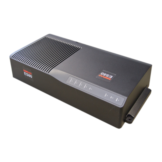
Processor Unit. Related topics Main system units, page 17 Simrad ES80, page 11 Wideband Transceiver (WBT) description The ES80 Wideband Transceiver (WBT) is provided to transmit acoustic energy through water. This transmission and reception are commonly referred to as a ping. After each transmission, the transceiver receives the echoes from the targets in the water and/or the seabed. -
Page 22: Transducers
Transducers The ES80 Wideband fish finding echo sounder can be used with all our single-beam and split-beam transducers. Kongsberg Maritime can provide a wide range of efficient and accurate Simrad transducers for the ES80 Wideband fish finding echo sounder. A large number of operational frequencies is available. -
Page 23: Scope Of Supply
To assemble a complete ES80 system, you will need a set of system units. The main units required are provided with the standard delivery. Other required units may be purchased from Kongsberg Maritime or obtained locally. Some units are optional. When you unpack the parts provided with the ES80 delivery, make sure that the following items are included. - Page 24 Operational software Operational software is provided on a suitable media. If the Processor Unit is purchased from Kongsberg Maritime, the operational software is installed on the Processor Unit, and ready for use. End-user documentation End-user documentation is provided on paper and/or digital formats.
- Page 25 Simrad ES80 Related topics Scope of supply, page 21 Simrad ES80, page 11 416739/A...
-
Page 26: Additional Required Items
ES80 for full operational functionality. The additional items can be provided by Kongsberg Maritime. You can order them with the other basic ES80 items. You can also purchase these items from your dealer, agent or local supplier. - Page 27 The computer is not a standard part of the ES80 delivery. This is a commercial item that can be purchased locally. The Simrad ES80 system is designed to be controlled by a maritime computer. The computer must be designed for rugged use, and the construction must be able to withstand the vibrations and movements of a vessel.
- Page 28 The ES80 Wideband fish finding echo sounder must be connected to one or more transducers. Kongsberg Maritime can provide a wide range of efficient and accurate Simrad transducers for the ES80 Wideband fish finding echo sounder. A large number of operational frequencies is available.
-
Page 29: Additional Optional Items
If the distance between the Processor Unit and your second display is considerable, we suggest that you use KVM (Keyboard Video Mouse) technology to preserve the video quality. Kongsberg Maritime may provide a suitable display. Consult your local dealer or agent for more information. - Page 30 Simrad ES80 Installation Manual Global positioning system (GPS) A global positioning system (GPS) must be connected to the ES80. When a global positioning system (GPS) connected to the ES80, the vessel’s current geographical position can be presented in the user interface. It will also provide latitude and longitude information for the cursor and marker(s).
- Page 31 • EM Attitude 3000 The Kongsberg EM Attitude 3000 is a proprietary datagram format created by Kongsberg Maritime for use with digital motion sensors. It holds roll, pitch, heave and heading information. The datagram contains a 10-byte message.
- Page 32 Simrad ES80 Installation Manual In the box Motion Reference Unit (MRU) Order number – Seatex MRU-D Motion Reference Unit (MRU) Documentation An order number is the unique identifier used when a unit or an item is ordered. The number identifies a complete unit and relevant accessories packed in its shipping container.
- Page 33 Output voltage • : The output power must exceed the requirements of the ES80. Output power • : The output AC voltage must be a sine wave. Output form Related topics Scope of supply, page 21 Simrad ES80, page 11 416739/A...
-
Page 34: General Safety Rules
Simrad ES80 Installation Manual General safety rules The following safety precautions must be followed at all times during installation and maintenance work: WARNING This equipment operates on 230 VAC at 50/60 Hz. This voltage is lethal! You must never work alone on high-voltage equipment! •... -
Page 35: Installation Requirements
-15% to +20% of the nominal voltage (except under fault conditions). Related topics Installation requirements, page 33 Simrad ES80, page 11 Uninterruptible power supply (UPS) requirements We recommend that the ES80 system is powered using an Uninterruptible Power Supply (UPS) with sine wave output. -
Page 36: Cables And Wiring Requirements
Simrad ES80 Installation Manual Cables and wiring requirements Correct wiring is crucial for the operational performance of the ES80. All cables running between system cabinets located in different rooms and/or on different decks must be supported and protected along their entire lengths using conduits and/or cable trays. -
Page 37: Noise Sources
Note Ensure maximum physical distance between the Wideband Transceiver (WBT) and the Power Supply Unit. This is important to reduce noise. Related topics Installation requirements, page 33 Simrad ES80, page 11 416739/A... -
Page 38: Dry Docking Requirements
Simrad ES80 Installation Manual Dry docking requirements Whenever one or more transducers are mounted under the vessel’s hull, special considerations must be made prior to dry docking. Make sure that ample clearance is provided under the transducers when you are placing the vessel in dry dock. -
Page 39: Network Security
The customer/end user of the ES80 system will always be in charge of defining and implementing a security policy, and providing the relevant network security applications. Note Kongsberg Maritime will not accept any responsibility for errors and/or damages caused by unauthorized use of or access to the ES80. Related topics... -
Page 40: Support Information
Simrad ES80 Installation Manual Support information If you need technical support for your Simrad ES80 you must contact your local dealer, or one of our support departments. A list of all our offices and dealers is provided on our website. You can also contact our main support office in Norway. - Page 41 Simrad ES80 • : Kongsberg Underwater Technology Inc / Simrad Fisheries Company name • : 19210 33rd Ave W, Suite A, Lynnwood, WA 98036, USA Address • : +1 425 712 1136 Telephone • : +1 425 712 1193 Telefax •...
- Page 42 Simrad ES80 Installation Manual China • : Kongsberg Maritime China Ltd Company name • : 555 Chuanqiao Road, China (Shanghai) Pilot Free Trade Zone, 201206, China Address • : +86 21 3127 9888 Telephone • : +86 21 3127 9555 Telefax •...
-
Page 43: Preparations
Preparations Preparations Topics Installation summary, page 42 About installation drawings, page 44 Tools, equipment and consumables required for ES80 installation, page 44 Personnel qualifications, page 45 Where to install the transducer, page 46 Acoustic noise, page 53 Vessel coordinate system, page 61 416739/A... -
Page 44: Installation Summary
Simrad ES80 Installation Manual Installation summary Installation of the ES80 is a demanding task that requires careful preparations, a number of specific procedures, wiring and required system settings. Context An overall installation procedure is provided. This procedure does not describe any detailed tasks. - Page 45 Preparations Note The installation shipyard must provide all necessary design and installation drawings, as well as the relevant work standards and mounting procedures. If required, all documents provided by the shipyard for the physical installation of the ES80 must be approved by the vessel’s national registry and corresponding maritime authority and/or classification society.
-
Page 46: About Installation Drawings
The shipowner and shipyard doing the installation are responsible for obtaining and paying for such approval. Kongsberg Maritime offers free advice for installation planning. Proposed arrangements may be sent for commentary or suggestions. The following drawings should be submitted should assistance be requested: •... -
Page 47: Personnel Qualifications
Preparations spanners, a cable stripper, a soldering iron, etc. Each tool must be provided in various sizes. We recommend that all tools are demagnetized to protect your equipment. However, you must make sure that the following specialized tools are available. •... -
Page 48: Where To Install The Transducer
Simrad ES80 Installation Manual Where to install the transducer A single answer to the question "where to install the transducer" cannot be given. The physical location of the transducer depends on the vessel's design and construction, how the hull is shaped, and how the water runs along the hull. There are however a number of important guidelines, and some of these are even conflicting. -
Page 49: Avoid Protruding Objects Near The Transducer
The effect of slamming can be reduced by mounting the transducer as deep as possible on the hull. Note Kongsberg Maritime AS takes no responsibility for any damages to the transducer, the cable or the mounting arrangement, caused by slamming. Related topics... -
Page 50: Mount The Transducer At Forward Part Of Hull To Minimize The Effects From The Flow Boundary Water Layer
Simrad ES80 Installation Manual be extruding from the transducer, the installation hardware or the hull plating. If necessary, grind and polish all surfaces. Related topics Where to install the transducer, page 46 Preparations, page 41 Mount the transducer at forward part of hull to minimize the... -
Page 51: Keep The Transducer Far Away From The Propellers
Preparations It is our experience that a wide and flat bottom, with a rising angle less than around 13 degrees, is prone to giving air problems for the transducer. In any case a transducer location in the forward part of the hull is preferred in order to minimise the influence of the boundary layer. - Page 52 Simrad ES80 Installation Manual Related topics Where to install the transducer, page 46 Preparations, page 41 416739/A...
-
Page 53: Summary And General Recommendations
Preparations Summary and general recommendations Some of the installation guidelines provided for transducer location may be conflicting. For this reason, each vessel must be treated individually in order to find the best compromise. In general, the most important factor is to avoid air bubbles in front of the transducer face. For this reason, the recommended transducer location is normally in the fore part of the hull, well ahead of the noise created by the bow wave. - Page 54 Simrad ES80 Installation Manual If the vessel hull has a bulbous bow, this may well be a good transducer location, but also in this case the flow pattern of the aerated water must be taken into consideration. The foremost part of the bulb is often a good location.
-
Page 55: Acoustic Noise
Preparations Acoustic noise As with any other hydroacoustic systems, the quality of the ES80 echo data and presentations are subject to unwanted acoustic noise. The echoes from any large and small target must be detected inside the noise. It is important that we keep the noise level as low as possible. This is necessary to obtain long range and dependable interpretations of the echoes. - Page 56 Simrad ES80 Installation Manual Signal-to-noise ratio (often abbreviated SNR or S/N) is a measure used in science and engineering that compares the level of a desired signal to the level of background noise. It is defined as the ratio of signal power to the noise power, often expressed in decibels.
-
Page 57: Self Noise
Preparations The preamplifiers are very sensitive, and they can easily pick up electrical noise from internal and external power supplies. The preamplifiers are also vulnerable to analogue noise created by their own electronic circuitry. Digital noise created by the converter and processing circuitry can also create problems. - Page 58 Simrad ES80 Installation Manual Propeller noise is usually water-borne. In some cases, however, shaft vibrations or vibrations in the hull near the propeller may be structure-borne to the transducer. If a propeller blade is damaged, this may increase the noise considerably.
- Page 59 Preparations Turbulent flow Laminar flow Air bubbles Air bubbles absorb and reflect the sound energy, and they may in worst cases block the sound transmission altogether. The boundary layer increases in thickness when it becomes turbulent. The boundary layer is thin in the forward part of the vessel hull, and increases as it moves aft. The thickness depends on ships speed and on the roughness of the hull.
-
Page 60: Ambient Noise
Simrad ES80 Installation Manual Related topics Acoustic noise, page 53 Preparations, page 41 Ambient noise Ambient noise is usually not a limiting factor to the performance of sonars and echo sounders. The ambient noise may be split up as follows: •... -
Page 61: Electrical Self Noise
Preparations Electrical self noise Electrical or electronic self noise is picked up or generated in any other part of the equipment than the transducer. The most common source of electrical self noise is hum. The hum is normally generated by a power supply. It is then picked up by the transducer cables and/or sensitive electronic circuitry. - Page 62 Simrad ES80 Installation Manual Reducing flow noise • The shape of the transducer (or dome around it) must be as streamlined as possible. • The hull plating in front of the transducer must be as smooth as possible. Important Be especially aware of bilge keels and zinc alloy anodes.
-
Page 63: Vessel Coordinate System
Preparations Reducing interference Interference from the transmission pulses from other hydroacoustic instruments on board the vessel is difficult to avoid. The problem may be reduced by choosing the working frequencies carefully and to some extent by separating the different transducers. On vessels with a large number of separate hydroacoustic systems installed and in simultaneous use, a separate synchronizing system (for example the K-Sync) should be considered. - Page 64 Simrad ES80 Installation Manual positioned far away from the transducer on a depth sensor, which may be located closer to the bow. Very often, the information from one sensor depends on data from an other. It is then important that the relevant measurements are compensated for these relative distances.
- Page 65 Preparations • The physical location of the motion reference unit (MRU) Coordinate system alternative origins If necessary, other origin locations may be defined for specific products or purposes. One example is the Navigation Reference Point that is frequently used. Whenever a vessel is surveyed to establish accurate offset information, the surveyor may also establish an alternative origin location.
-
Page 66: Installing The Es80 Hardware Units
Simrad ES80 Installation Manual Installing the ES80 hardware units Topics Installing the Wideband Transceiver (WBT) using the integrated brackets, page 65 Installing the Wideband Transceiver (WBT) in a 19" rack, page 67 Installing the WBT Power Supply, page 69 Installing the display, page 71... -
Page 67: Installing The Wideband Transceiver (Wbt) Using The Integrated Brackets
Installing the ES80 hardware units Installing the Wideband Transceiver (WBT) using the integrated brackets The ES80 Wideband Transceiver (WBT) is normally positioned in a dedicated room in the vicinity of the transducer. The physical length of the cables limit the distance between each transducer and the Wideband Transceiver (WBT). - Page 68 Simrad ES80 Installation Manual Procedure Prepare the location and the necessary tools. Observe the installation requirements. Depending on the local requirements and preferences, the Wide Band Transceiver (WBT) can be installed on the bulkhead, inside a console, in a cabinet or 19”...
-
Page 69: Installing The Wideband Transceiver (Wbt) In A 19" Rack
Installing the ES80 hardware units Installing the Wideband Transceiver (WBT) in a 19" rack The Wideband Transceiver (WBT) can be installed in a 19-inch rack by means of an optional drawer. You will need one drawer for each Wideband Transceiver (WBT) unit. Prerequisites It is assumed that a suitable 19–inch rack has already been installed. - Page 70 Simrad ES80 Installation Manual Depending on the local requirements and preferences, the Wide Band Transceiver (WBT) can be installed on the bulkhead, inside a console, in a cabinet or 19” rack, or on a desk. The position must be chosen to fit the available cable lengths between the Wideband Transceiver (WBT) and the other units it connects to.
-
Page 71: Installing The Wbt Power Supply
Installing the ES80 hardware units Installing the WBT Power Supply The power supply provided with the Wide Band Transceiver (WBT)is a commercial type custom made for the ES80. A dedicated installation procedure is provided. Prerequisites A suitable location for the power supply must be defined prior to installation. If you place the unit on the bridge, observe the compass safe distance. - Page 72 Simrad ES80 Installation Manual The chosen position must fit the available cable lengths between the power supply, the transceiver and the AC mains power outlet. If you place the unit on the bridge, observe the compass safe distance. Make sure that enough space is made available for maintenance purposes.
-
Page 73: Installing The Display
Installing the ES80 hardware units Installing the display A display is a required part of the ES80 Wideband fish finding echo sounder. For best readability, the display must be protected from glare and have the correct height and angle. The display is normally not included with the ES80 delivery. A generic procedure is provided. -
Page 74: Installing The Cehw Processor Unit
Simrad ES80 Installation Manual Connect the cables. Note When you connect the cables, make sure that they are all properly secured, and able to withstand the vibration and movements of the vessel. Related topics Installing the ES80 hardware units, page 64... - Page 75 Installing the ES80 hardware units Make sure that the installation method allows for the physical vibration, movements and forces normally experienced on a vessel. Note In order to allow for future maintenance, we recommend to mount the unit with its cables and connectors available for easy access.
-
Page 76: Installing A Commercial Computer
Simrad ES80 Installation Manual Installing a commercial computer The Processor Unit can be installed inside a console, inside a suitable cabinet, in a 19" rack or on a desk. Make sure that adequate ventilation is available to avoid overheating. Prerequisites You must be equipped with a standard set of tools. - Page 77 Installing the ES80 hardware units Make sure that the installation method allows for the physical vibration, movements and forces normally experienced on a vessel. Note In order to allow for future maintenance, we recommend to mount the unit with its cables and connectors available for easy access.
-
Page 78: Installing The Ethernet Switch
Simrad ES80 Installation Manual Installing the Ethernet switch If you use more than one Wideband Transceiver (WBT), a high capacity Ethernet switch is required. The Ethernet switch is used to connect each Wideband Transceiver (WBT) to the Processor Unit. Prerequisites You must be equipped with a standard set of tools. -
Page 79: Installing The Transducer(S)
End user manuals and source drawings (normally in AutoCad format) can be downloaded from our website. • https://www.kongsberg.com/td Procedure Determine the physical location of the transducer. The decision must be based on: • The vessel drawings •... - Page 80 Simrad ES80 Installation Manual Pull the transducer cable up through the steel conduit. Tighten the packing nipple on the cable gland properly to avoid leaks. Mount the transducer. 10 Seal the top of the steel conduit to prevent water leaks.
-
Page 81: Cable Layout And Interconnections
Cable layout and interconnections Cable layout and interconnections Topics Read this first, page 80 Reducing electrical noise, page 80 Cable plans, page 82 List of ES80 cables, page 87 Installing the ES80 cables, page 89 Setting up the ES80 in a synchronized system, page 105 Cable drawings and specifications, page 116 Basic cable requirements, page 143 416739/A... -
Page 82: Read This First
Read this first Detailed information about cable specifications, termination and connectors is provided. Unless otherwise specified, all cables are supplied by Kongsberg Maritime as a part of the ES80 delivery. Detailed drawings are provided for relevant cables. Each drawing provides additional information, and may, when applicable, include minimum specifications, connector terminations and the required number of cores. - Page 83 Cable layout and interconnections • Place the transducer cables in a metal conduit all the way from the transducer to the transceiver. Terminate the conduit as close to the transducer and transceiver as possible. • Make sure that the transducer cables are completely separated from other cables, boxes, other potential noise sources.
-
Page 84: Cable Plans
• Standard transceiver setup with one Wideband Transceiver (WBT) unit. • Standard transceiver setup with two Wideband Transceiver (WBT) units. The Wideband Transceiver (WBT) used by the Simrad ES80 can be set up to work with maximum four -4- operational frequencies. This means that you can use four single frequency/single beam transducers, two dual frequency transducers, or one split beam transducer. -
Page 85: Topside Cable Plan
Cable layout and interconnections Topside cable plan The topside/bridge cables include those used to connect the ES80 Processor Unit and the display to each other, to AC mains power, and to external devices. One high capacity Ethernet cable connects the Processor Unit to the Wideband Transceiver (WBT). Display (You can use more than one display on your ES80 Processor Unit depending on personal and/or operational preferences.) Processor Unit (A computer keyboard is optional.) - Page 86 Simrad ES80 Installation Manual Related topics Cable plans, page 82 Cable layout and interconnections, page 79 416739/A...
-
Page 87: Sonar Room Cable Plan With One Transceiver
Cable layout and interconnections Sonar room cable plan with one transceiver The Wideband Transceiver (WBT) cables include those used to connect the ES80 transceiver(s) to AC mains power, and to the transducer(s). Wideband Transceiver (WBT) Power Supply Unit Depending on the operational requirements, one or more Wideband Transceiver (WBT) units may be used in the complete ES80 system. -
Page 88: Sonar Room Cable Plan With Two Transceivers
Simrad ES80 Installation Manual Sonar room cable plan with two transceivers The Wideband Transceiver (WBT) cables include those used to connect the ES80 transceiver(s) to AC mains power, and to the transducer(s). Wideband Transceiver (WBT) Power Supply Unit Ethernet switch Depending on the operational requirements, one or more Wideband Transceiver (WBT) units may be used in the complete ES80 system. -
Page 89: List Of Es80 Cables
Cable layout and interconnections List of ES80 cables A set of cables is required to connect the ES80 units to each other, and to the relevant power source(s). Additional cables are required to connect the ES80 to peripheral devices. Cables identified with an asterisk (*) are system or commercial cables. These cables are provided with the ES80 delivery or the relevant item. - Page 90 Simrad ES80 Installation Manual Cable Type From/To Minimum requirements Synchronization From Wideband Transceiver (WBT) 4 x 0.5 mm² Auxiliary socket to external cable synchronisation system. If you use more than one Wideband Transceiver (WBT) in your ES80 system, all synchronization input signals to the Auxiliary ports must be provided by the same source.
-
Page 91: Installing The Es80 Cables
Cable layout and interconnections Installing the ES80 cables Topics Prerequisites for cable installation, page 89 Installing the ES80 topside cables, page 90 Installing the Wideband Transceiver (WBT) cables, page 92 Connectors on the Nexcom Processor Unit, page 94 Connectors on the CEHW Processor Unit, page 96 Wideband Transceiver (WBT) connectors, page 99 Using a steel conduit to protect the transducer cable, page 100 Splicing the transducer cable, page 102... -
Page 92: Installing The Es80 Topside Cables
Only skilled and authorized personnel can install the ES80 cables. Kongsberg Maritime will not accept any responsibility for errors, malfunctions or damage to system or personnel caused by improper wiring. Related topics... - Page 93 Cable layout and interconnections Connect the video cable from the Processor Unit to the display. (C5) The display cable is often physically attached to the display, and terminated in the “computer end” with a male connector. If the cable is not attached, it is normally provided with the display.
-
Page 94: Installing The Wideband Transceiver (Wbt) Cables
Simrad ES80 Installation Manual Connect the serial cables from the Processor Unit to the relevant external devices. (C10) For more information, see the cable details: • Cable drawings and specifications, page 116 If applicable, connect the signal cable from the Processor Unit to the synchronization system. - Page 95 Cable layout and interconnections This cable must be provided by the installation shipyard. For more information, see the cable details: • Ground cable, page 119 If you wish to use the synchronization method offered by the Auxiliary socket on the Wideband Transceiver (WBT), make the necessary connection.
-
Page 96: Connectors On The Nexcom Processor Unit
Simrad ES80 Installation Manual Connectors on the Nexcom Processor Unit The rear panel of the Nexcom NISE 3600 Processor Unit holds all the connectors used by the computer to communicate with external devices. One slot is empty for future expansions. - Page 97 Cable layout and interconnections capacity you will reduce the ES80 performance. Do not connect the Processor Unit to the Wideband Transceiver (WBT) using an existing local area network (LAN). USB (Universal Serial Bus) sockets (USB 3.0) USB (Universal Serial Bus) sockets (USB 2.0) From Processor Unit to keyboard (C6) From Processor Unit to mouse (or another similar device) (C7) Graphic adapter (Output format SVGA) (C5)
-
Page 98: Connectors On The Cehw Processor Unit
Simrad ES80 Installation Manual Connectors on the CEHW Processor Unit Connections are made to both sides of the computer. By default, the COM ports are set up as follows: • COM1 is set up for RS-232 serial interface. • COM2 and COM3 are set up for RS-232 serial interface. - Page 99 Cable layout and interconnections Serial cables: From Processor Unit to external device(s) (C10) COM2 and COM3 are set up for RS-232 serial interface. COM4 and COM5 are set up for RS-422 serial interface. Video cable: From Processor Unit to display (C5) Ethernet cable: From Processor Unit to Wideband Transceiver (WBT) (C8) Note Use only the left socket (ETH1) to communicate with the transceiver.
- Page 100 Simrad ES80 Installation Manual Related topics Installing the ES80 cables, page 89 Cable layout and interconnections, page 79 Cable drawings and specifications, page 116 Basic cable requirements, page 143 416739/A...
-
Page 101: Wideband Transceiver (Wbt) Connectors
Cable layout and interconnections Wideband Transceiver (WBT) connectors All sockets for the system cables are located on the Wideband Transceiver (WBT) side panel. Ground cable: From Wideband Transceiver (WBT) to vessel ground (C15) Transducer cable: From Wideband Transceiver (WBT) to transducer (C20) Ethernet cable: From Wideband Transceiver (WBT) to Processor Unit (C8) DC power cable: From Wideband Transceiver (WBT) to Power Supply Unit (C16) Auxiliary connector for synchronization (Optional) -
Page 102: Using A Steel Conduit To Protect The Transducer Cable
Simrad ES80 Installation Manual Using a steel conduit to protect the transducer cable A steel conduit must be used to protect the transducer cable. The steel conduit must preferably be straight. Start the conduit immediately above the transducer, and terminate it well above the water line. - Page 103 Cable layout and interconnections Steel conduit minimum dimensions The dimensions of the steel conduit must be specified and/or verified by the relevant maritime authority and/or classification society. The minimum dimensions are: • : 35 mm Inside diameter • Wall thickness –...
-
Page 104: Splicing The Transducer Cable
• The necessary length of transducer cable. The cable between the junction box and the transceiver must be supplied by Kongsberg Maritime, and this must be the same type as used on the transducer. - Page 105 Cable layout and interconnections The junction box is isolated from vessel ground. Cable gland Terminal block Cable Cable screen (Do not connect the cable screen to vessel ground.) Procedure Mount the junction box in a suitable location. Terminate the steel conduits containing the transducer cable as close to the junction box as possible.
- Page 106 Simrad ES80 Installation Manual Junction box Cable gland Terminal block Cable Cable screen (Do not connect the cable screen to vessel ground.) The junction box may be connected to vessel ground. Procedure Mount the junction box in a suitable location.
-
Page 107: Setting Up The Es80 In A Synchronized System
— April 2016 The Simrad ES80 may be set up to be synchronized with other hydroacoustic instruments. Synchronization is necessary to prevent several hydroacoustic systems from transmitting simultaneously. Individual transmission is often a necessity to prevent interference. -
Page 108: Synchronization Modes
Simrad ES80 Installation Manual Synchronization modes The purpose of the synchronization modes are to set up the ES80 to operate alone, or as a "master" or "slave" in a synchronized system. Whenever more than one hydroacoustic system is installed on a vessel, interference may occur. -
Page 109: Synchronization Sequences
Cable layout and interconnections Synchronization sequences In many applications, the synchronisation interface is based on an RS-232 serial port. When you connect two systems for synchronisation using Clear to Send (CTS) and Request to Send (RTS), one system must set up as a "Master" and the other as a "Slave". When the ES80 is "Master"... -
Page 110: Synchronization Using Clear To Send (Cts) And Request To Send (Rts) Signals
Simrad ES80 Installation Manual Related topics Setting up the ES80 in a synchronized system, page 105 Cable layout and interconnections, page 79 Synchronization using Clear To Send (CTS) and Request To Send (RTS) signals In many applications, the synchronisation interface is based on an RS-232 serial port. Only the Clear to Send (CTS) and Request to Send (RTS) connections of the RS-232 interface are then used. -
Page 111: Synchronization Using The Auxiliary Socket On The Transceiver
The socket fits a Conxall 7-pin Mini-Con-X ® shielded plug. The connections are made on pins 2, 3 and 5. The plug can be ordered from the manufacturer or purchased from Kongsberg Maritime. Use part number 387563. • : Switchcraft Conxall Manufacturer •... -
Page 112: Synchronizing The Es80 By Means Of A Serial Port
Simrad ES80 Installation Manual Related topics Setting up the ES80 in a synchronized system, page 105 Cable layout and interconnections, page 79 Synchronizing the ES80 by means of a serial port If you want to use the ES80 as a master or slave in a synchronized system, you must set it up for such operation. - Page 113 Cable layout and interconnections Procedure Connect the synchronization cable from the remote system to an available communication port on your Processor Unit. This is described in the Cable layout and interconnections chapter. Observe the applicable requirements related to cabling. Make sure that the total length of the serial line cable does not exceed approximately 50 meters.
- Page 114 Simrad ES80 Installation Manual Master mode is used if the ES80 is going to act as the controlling unit in a synchronized system. The peripheral hydroacoustic system(s) are only permitted to transmit when enabled by the ES80. When Master mode is selected, the ES80 will run using its internal ping interval parameters and send trigger signals to the peripheral system(s).
-
Page 115: Synchronizing The Es80 By Means Of The Auxiliary Port
The socket fits a Conxall 7-pin Mini-Con-X shielded plug. The connections are made on pins 2, 3 and 5. The plug can be ordered from the manufacturer or purchased from Kongsberg Maritime. Use part number 387563. • : Switchcraft Conxall Manufacturer •... - Page 116 Simrad ES80 Installation Manual The parameters on the page allow you to choose which communication port Synchronization to use for the physical connection to the external system, and which synchronization mode to use. The page is located in the dialog box on the menu.
- Page 117 Cable layout and interconnections Related topics Setting up the ES80 in a synchronized system, page 105 Cable layout and interconnections, page 79 Interfacing peripheral equipment, page 192 Setting to work, page 153 416739/A...
-
Page 118: Cable Drawings And Specifications
Simrad ES80 Installation Manual Cable drawings and specifications Topics AC power cable using IEC C13 inline socket, page 117 Ground cable, page 119 RS-232 serial line connection using three wires, page 120 RS-232 serial line connection using five wires, page 121... -
Page 119: Ac Power Cable Using Iec C13 Inline Socket
Cable layout and interconnections AC power cable using IEC C13 inline socket This cable is used to connect any unit or device to AC mains supply. It is commercial, and normally used for 115 and 230 VAC. The inline socket and plug comply to the IEC60320 standard. - Page 120 Simrad ES80 Installation Manual Note There are substantial differences between American and British nomenclature related to power plugs and sockets. Observe local standards and regulations. Minimum cable requirements • : 2 x 1.5 mm + 1.5 mm Ground Conductors •...
-
Page 121: Ground Cable
Cable layout and interconnections Ground cable Correct grounding is essential for safe operation and maximum performance. Ground tag on unit Vessel ground The ground connection is made using a thick stranded (or yellow/green) cable making a solid connection between the cabinet and the bulkhead. -
Page 122: Rs-232 Serial Line Connection Using Three Wires
Simrad ES80 Installation Manual RS-232 serial line connection using three wires An RS-232 serial line connection using three (3) wires and NMEA datagrams is a common way to connect the ES80 to external devices. Local connection Connection on remote device... -
Page 123: Rs-232 Serial Line Connection Using Five Wires
Cable layout and interconnections RS-232 serial line connection using five wires An RS-232 serial line connection using five (5) wires and NMEA datagrams is a common way to connect the ES80 to external devices. Local connection Connection on remote device Female 9-pin D-Subminiature connector Male 9-pin D-Subminiature connector Unless otherwise specified, this cable must be provided... -
Page 124: Cehw03 Rs-232 Serial Line Connection Using Three Wires
Simrad ES80 Installation Manual CEHW03 RS-232 serial line connection using three wires An RS-232 serial line connection using three (3) wires and NMEA datagrams is a common way to connect the ES80 to external devices. COM1, COM2 and COM3 are set up for RS-232 serial interface. -
Page 125: Cehw03 Rs-422 Serial Line Connection Using Five Wires
Cable layout and interconnections CEHW03 RS-422 serial line connection using five wires An RS-422 serial line connection can transmit data at rates as high as 10 million bits per second, and may be sent on cables as long as 1500 meters. COM4 and COM5 are set up for RS-422 serial interface. -
Page 126: Used As Synchronization Trigger (Input Or Output)
Simrad ES80 Installation Manual RS-232 used as synchronization trigger (input or output) An RS-232 serial line connection using the Request To Send (RTS) and Clear To Send (CTS) signals is common way to connect the ES80 to external devices for synchronization purposes. -
Page 127: Rj45 High Speed Ethernet Cable (1000Base-T)
Cable layout and interconnections RJ45 High speed Ethernet cable (1000Base-t) Most high speed data connections between the ES80 system units are made using Ethernet cables. These cables may also be used between the ES80 and peripheral equipment. Local Ethernet connection Connection on external network device Ethernet cables are available... -
Page 128: Battery Power Cable
ES80 delivery. You can use this plug if you wish to operate the transceiver from a battery. The plug can be ordered from the manufacturer or purchased from Kongsberg Maritime. Use part number 390616. • : Switchcraft Conxall Manufacturer •... -
Page 129: K-Sync Interface To Generic Rs-232 Synchronization Input
Cable layout and interconnections K-Sync interface to generic RS-232 synchronization input For transmission synchronization purposes, the K-Sync will interface a generic RS-232 serial line communication port using the CTS (Clear To Send) and RTS (Request To Send) signals. The synchronized product is connected to the IO Module inside the K-Sync Synchronizing Unit. - Page 130 Simrad ES80 Installation Manual Connectors 1 through 6 as indicated by the arrows. Note that each of the two connector elements can be pulled out of the IO Module for easy access. Configuration board Unless otherwise specified, this cable must be provided by the installation shipyard.
-
Page 131: Simrad Tu40 Interface To Generic Rs-232 Synchronization Input
Cable layout and interconnections Simrad TU40 interface to generic RS-232 synchronization input For transmission synchronization purposes, the Simrad TU40 will interface a generic RS-232 serial line communication port using the CTS (Clear To Send) and RTS (Request To Send) signals. The NotUsed provides one output and one input for each hydroacoustic system that needs to be synchronized. - Page 132 Simrad ES80 Installation Manual Screen (Cable screen) (Green) Input (Ready to Transmit (RTT)) Ground (Signal ground) Output (Trigger Out) Make the connections here. Channels (From left) Minimum cable requirements Unless otherwise specified, this cable must be provided by the installation shipyard. If you need to install a very long cable, increase the cross section.
-
Page 133: Auxiliary Connector For Synchronization
The socket fits a Conxall 7-pin Mini-Con-X ® shielded plug. The connections are made on pins 2, 3 and 5. The plug can be ordered from the manufacturer or purchased from Kongsberg Maritime. Use part number 387563. • : Switchcraft Conxall Manufacturer •... -
Page 134: Single Beam Low Power Transducer Connection To A Circular Transducer Socket
Simrad ES80 Installation Manual Single beam low power transducer connection to a circular transducer socket Maximum four single beam low power transducers can be connected to terminals A through J on the circular 12-pin Amphenol transducer socket (Type 97-12-19S). This socket is used on the General Purpose Transceiver (GPT), and on several versions of the Wide Band Transceiver (WBT). -
Page 135: Split Beam Transducer Connection To An Amphenol Socket
License 1 License 2 License 3 License 4 Minimum cable requirements Not applicable. If you need an extension cable, contact your dealer (or Kongsberg Maritime) for support. Related topics Cable drawings and specifications, page 116 Cable layout and interconnections, page 79... - Page 136 Simrad ES80 Installation Manual Note We strongly recommend that you install the transducer cable in a steel conduit. Depending on production date, the transducer can be delivered with two different cable types. On older transducers the cable contains black and white conductors. On new transducers the cable contains colour coded conductors.
- Page 137 Cable layout and interconnections sectors as seen in the illustration and table. The different numbers are quite small and you may need a magnifying glass to see them. Note Since the white conductors are not numbered, it is very important to find the pairs that are twisted together.
- Page 138 • Splicing using a junction box that is isolated from vessel’s ground Refer to the dedicated procedures. Minimum cable requirements Not applicable. If you need an extension cable, contact your dealer (or Kongsberg Maritime) for support. Note The software license controls how the transducer is connected to the Wideband Transceiver (WBT).
-
Page 139: Split Beam Transducer Connection For Single Beam Use On An Amphenol Socket
Cable layout and interconnections Split beam transducer connection for single beam use on an Amphenol socket A split beam transducer can be connected to sockets A and D on a circular 12-pin Amphenol transducer socket (Type 97-12-19S). This allows you to use the transducer as a single beam unit. - Page 140 Simrad ES80 Installation Manual Cable with colour coded conductors Cable with colour coded conductors Sector Cable colours Terminal on socket Transceiver channel White Black Green Black Yellow Black Blue Black Digital output Digital ground Black Cable screen Screen Do not connect Digital output and Digital ground to the transceiver socket.
- Page 141 • Splicing using a junction box that is isolated from vessel’s ground Refer to the dedicated procedures. Minimum cable requirements Not applicable. If you need an extension cable, contact your dealer (or Kongsberg Maritime) for support. Related topics Cable drawings and specifications, page 116...
-
Page 142: About Serial Lines
Simrad ES80 Installation Manual About serial lines A preferred method to establish communication between the ES80 and peripheral devices, is by means of serial lines. Several serial line standards are available, each with different qualities. Unless otherwise specified, these cables must be provided by the installation shipyard. - Page 143 Cable layout and interconnections specified for multi-drop applications. This means that one transmitter can send data to up to 10 receivers. Note There are no common standard for RS-422 pin configuration. Any manufacturer may choose their own connector pins for the various signals used. In order to make the RS-422 connection to your peripheral device work properly, you must always consult the relevant instructions provided by the device manufacturer.
- Page 144 Simrad ES80 Installation Manual Related topics Cable drawings and specifications, page 116 RS-232 serial line connection using three wires, page 120 RS-232 serial line connection using five wires, page 121 CEHW03 RS-232 serial line connection using three wires, page 122...
-
Page 145: Basic Cable Requirements
Cable layout and interconnections Basic cable requirements It is very important that all systems cables are installed correctly. All cables must be properly supported and protected, and all relevant precautions must be made to prevent unwanted noise. Topics Cable trays, page 143 Radio frequency interference, page 144 Physical protection of cables, page 145 Grounding of system cables, page 145... -
Page 146: Radio Frequency Interference
Simrad ES80 Installation Manual Cables containing insulation materials with different maximum-rated conductor temperatures should not be bunched together (that is, in a common clip, gland, conduit or duct). When this is impractical, the cables must be carefully arranged such that the maximum temperature expected in any cable in the group is within the specifications of the lowest-rated cable. -
Page 147: Physical Protection Of Cables
Cable layout and interconnections Physical protection of cables Cables exposed to the risk of physical damage must be enclosed in a steel conduit or protected by a metal casing unless the cable's covering (for example armour or sheath) is sufficient to protect it from the damage risk. Cables exposed to an exceptional risk of mechanical damage (for example in holds, storage-spaces and cargo-spaces) must be protected by a suitable casing or conduit, even when armoured, if the cable covering does not guarantee sufficient protection for the cables. -
Page 148: Cable Connections And Terminations
Simrad ES80 Installation Manual Cable connections and terminations All cable connections are shown on the applicable cable plan and/or interconnection diagrams. Where the cable plan shows cable connections outside an equipment box outline, the connections are to be made to a plug or socket which matches the plug or socket on that particular item of equipment. -
Page 149: Cable Glands And Termination Procedures
There are many different types of cable gland on the market. The cable glands are not supplied with the system. Note Even though the cabinets from Kongsberg Maritime may be prepared for specific types of cable glands, the installation shipyard will be responsible for selecting cable gland types and installing them. - Page 150 There are many different types of cable gland on the market. This procedure describes the types used (now and previously) as standard in the units manufactured by Kongsberg Maritime. Even though the cabinets from Kongsberg Maritime may be prepared for specific types, the installation shipyard will be responsible for selecting cable gland types and installing them.
- Page 151 Cable layout and interconnections If the cable has not been installed in conduits: Measure the maximum length of wire required to reach from the cable gland to the terminal block(s) inside the cabinet. Add 20 cm, and mark the cable. Note The outer insulation on the cable will extend into the cable gland to a point approximately 5 mm outside the outer surface of the cabinet wall.
- Page 152 Simrad ES80 Installation Manual Take the appropriate safety measures, then replace the fuses and apply power to the system. Perform a relevant system test to ensure the installation has been made successfully. Related topics Basic cable requirements, page 143 Cable glands and termination procedures, page 147...
- Page 153 Cable layout and interconnections The illustrations and examples here are provided by the following manufacturer: Roxtec International AB Box 540 S-371 23 Karlskrona, SWEDEN • http://www.roxtec.com Illustration: Roxtec steps (Image from Roxtec website) The Roxtec system is available with a large number of various modules and compression units.
- Page 154 Simrad ES80 Installation Manual Further requirements For a complete installation procedure, refer to the relevant documentation provided by the manufacturer. Related topics Basic cable requirements, page 143 Cable glands and termination procedures, page 147 Cable layout and interconnections, page 79...
-
Page 155: Setting To Work
Setting to work Setting to work Topics Setting to work summary, page 154 Making sure that the ES80 is ready for operational use, page 156 Turning on the ES80 for the first time, page 164 Configuring the ES80 for normal operation, page 180 Placing each sensor in the vessel coordinate system, page 184 Interfacing peripheral equipment, page 192 Test procedures, page 221... -
Page 156: Setting To Work Summary
Simrad ES80 Installation Manual Setting to work summary Once all the hardware units have been installed, and all the cables have been connected, the ES80 can be turned on for the first time, and set to work. Prerequisites Before you can set the ES80 to work, the following work must be finalized. - Page 157 Setting to work • Configuring the ES80 for normal operation, page 180 Set up the interfaces with the external devices (navigation sensors and other peripherals). To provide correct information, the ES80 needs to communicate with external devices. All these interfaces must be set up in the ES80 user interface. •...
-
Page 158: Making Sure That The Es80 Is Ready For Operational Use
Simrad ES80 Installation Manual Making sure that the ES80 is ready for operational use Topics Making sure that the AC mains supply voltage is correct, page 156 Making sure that all ES80 cables are properly connected, page 157 Visual inspection of the display, page 158... -
Page 159: Making Sure That All Es80 Cables Are Properly Connected
Setting to work Related topics Making sure that the ES80 is ready for operational use, page 156 Setting to work, page 153 Making sure that all ES80 cables are properly connected The ES80 relies on communication between each system unit, and between the ES80 and external devices. -
Page 160: Visual Inspection Of The Display
You need the following equipment: • Multimeter Context This test procedure is only applicable when the display is provided by Kongsberg Maritime as a part of the ES80 delivery. Procedure Make sure that the display is installed in the correct location, and that it is suitably orientated with respect to ambient light conditions and reflections. - Page 161 Setting to work Make sure that the bolts, screws or studs that have been used are all of the correct size. Make sure that the correct flat and shake-proof washers have been used. Make sure that all the nuts have been tightened properly. Make sure that all welds and brackets have been painted with the correct preservation medium to prevent corrosion.
-
Page 162: Visual Inspection Of The Processor Unit
You need the following equipment: • Multimeter Context This test procedure is only applicable when the Processor Unit is provided by Kongsberg Maritime as a part of the ES80 delivery. Procedure Make sure that the computer is installed in the correct location, and that it is suitably oriented for replacement and cabling. - Page 163 Setting to work Make sure that the unit is not physically damaged, and that the surfaces and paint-work are clean without dents or scratches. The physical handling during the installation may have caused some minor scratches to the surfaces or paint-work. This can be accepted. However, if rough handling has caused serious damage, this must be recorded with a written statement and necessary photos, so that corrective actions can be made.
-
Page 164: Visual Inspection Of The Wideband Transceiver (Wbt)
Simrad ES80 Installation Manual Visual inspection of the Wideband Transceiver (WBT) A visual inspection of the Wideband Transceiver (WBT) is required to verify that the unit has not been physically damaged during the installation. If more than one Wideband Transceiver (WBT) is used, each must be inspected separately. - Page 165 Setting to work Make sure that the unit is not physically damaged, and that the surfaces and paint-work are clean without dents or scratches. The physical handling during the installation may have caused some minor scratches to the surfaces or paint-work. This can be accepted. However, if rough handling has caused serious damage, this must be recorded with a written statement and necessary photos, so that corrective actions can be made.
-
Page 166: Turning On The Es80 For The First Time
Simrad ES80 Installation Manual Turning on the ES80 for the first time Topics Setting up summary, page 164 Installing the ES80 operational software, page 166 Turning on the ES80 to Passive mode, page 167 Obtaining and installing the software license, page 168... - Page 167 Setting to work Turn on the Processor Unit. Make sure that you have administrative rights. Switch off any firewall applications. Open the operating systems’s Network and Sharing Center, and set the IP address for the network adapter used to communicate with the transceiver. •...
-
Page 168: Installing The Es80 Operational Software
Simrad ES80 Installation Manual Related topics Turning on the ES80 for the first time, page 164 Setting to work, page 153 Installing the ES80 operational software If your ES80 Wideband fish finding echo sounder is provided with a Processor Unit, the ES80 software has already been installed. -
Page 169: Turning On The Es80 To Passive Mode
Setting to work Depending on your operating system parameters, certain dialog boxes may open. The Windows ® Firewall may open a dialog box requesting information about the network. Select , and then select Public Allow access The operating system may also open other dialog boxes to verify that the ES80 software can run on the computer. -
Page 170: Obtaining And Installing The Software License
Simrad ES80 Installation Manual Turn on the display. If required, refer to the instructions provided by the display manufacturer. Turn on the Processor Unit. Wait while the operating system loads. On the Processor Unit desktop, double-click the ES80 icon to start the program. - Page 171 Setting to work Note Once you receive your software license string(s), do not lose them. We suggest that you copy the information into a text file (for example Notepad), and add relevant information. Place the text file on the Processor Unit desktop, and make sure that backup copies are made. In order to obtain a software license you must contact a Simrad dealer or distributor.
-
Page 172: Defining The Ip Address On The Processor Unit Network Adapter For Communication With The Wideband Transceiver (Wbt)
Simrad ES80 Installation Manual on an electronic format (e-mail or text file), you can copy the string from the source document and paste it into the dialog box. Type License String Select to save the license string and close the dialog box. -
Page 173: Installing One Or More Transducers
Setting to work On the list of connections, select , and then Internet Protocol 4 (TCP/IPv4) Properties Select , and type the IP address and network mask. Use the following IP address • : 157.237.15.12 IP Address Any address can be used, but 157.237.15.12 is recommended for legacy reasons. This is particularly important if your system contains old GPT transceivers. - Page 174 This allows each transceiver to optimise its performance for the individual transducer models. If you cannot find your transducer in the list, contact you dealer, agent or Kongsberg Maritime to upgrade the relevant software component in the ES80. Note Just making changes and selecting at the bottom of the page will not install anything.
- Page 175 Setting to work echo data that you export. If you do not have a computer keyboard connected to your ES80 system, select the button to open an on-screen keyboard. Keyboard Select mounting method. Specify the orientation of the transducer beam. •...
-
Page 176: Installing Transceiver Channels
Simrad ES80 Installation Manual identification and the serial number. The custom name is used several places in the user interface, and it can be changed. functionality on the page makes it possible to delete the Remove Transducer Installation information you have provided for the transducer. There is no "undo" functionality. - Page 177 Setting to work Note When you work in the dialog box, you must always select to save the Installation Apply changes made on a page. You must do this before you continue working on a different page. Procedure On the menu, select Setup Installation...
- Page 178 Simrad ES80 Installation Manual If you are using an Ethernet switch, make sure that it works. If you have changed the network settings, turn each transceiver off and on. The ES80 automatically assigns an IP address to each transceiver when they are turned off and on.
-
Page 179: Adjusting The Screen Resolution
Setting to work Adjusting the screen resolution Some computers have graphic adapters that are not able to detect the resolution of the current display. This limitation can also be caused by the display cable, or by imperfections in a display matrix system. In such cases, you must use the functionality of the operating system to adjust the screen resolution. -
Page 180: Restoring Correct Scaling Of The Es80 Presentation
Simrad ES80 Installation Manual If you are satisfied with the new resolution, select in the Keep changes acknowledge dialog box. Click the [X] in the top right corner to close the Control Panel. This procedure is made for the Microsoft ®... - Page 181 Setting to work Procedure On the Processor Unit, close the ES80 program. ® ® This procedure is made for the Microsoft Windows 7 operating system. In the bottom-left corner of your desktop, select the Windows ® button. Start On the right-hand side of the menu, select Start Control Panel...
-
Page 182: Configuring The Es80 For Normal Operation
Simrad ES80 Installation Manual Configuring the ES80 for normal operation Topics Selecting menu language, page 180 Selecting measurement units, page 181 Defining the file and folder settings for data recording, page 182 Selecting menu language You may prefer to use the ES80 with a user interface in your own language. -
Page 183: Selecting Measurement Units
Setting to work Selecting measurement units The ES80 is prepared to work with several international standards for units of measurements. From the page you control which units of measurements that are used. Units Context The ES80 user interface presents many measurements. These measurements are for example related to depth, range and distance. -
Page 184: Defining The File And Folder Settings For Data Recording
Simrad ES80 Installation Manual Defining the file and folder settings for data recording A useful function of the ES80 is it ability to record echo data. You can save the data to the Processor Unit hard disk, or onto an external storage device. To retrieve the data files you need to know where they are, and which file names that have been used. - Page 185 Setting to work On the page, define the recording parameters. File Setup Define the output directory for the recorded files. In order to change the output directory, the recording must be Off. Define a file name prefix. By adding a prefix to the file names you can identify the files you have recorded during a specific trip.
-
Page 186: Placing Each Sensor In The Vessel Coordinate System
Simrad ES80 Installation Manual Placing each sensor in the vessel coordinate system Topics Dimensional surveying, page 184 Surveying the transducer and the navigation sensors, page 185 Example procedure, page 186 Vessel coordinate system, page 189 Dimensional surveying Several sensors are connected to the ES80 to make its operation as accurate as possible. -
Page 187: Surveying The Transducer And The Navigation Sensors
Setting to work • Define a vessel coordinate system, and place all the sensors in it. Dimensional surveying The dimensional surveying tasks recommended for ES80 include: • Define the vessel coordinate system. The vessel coordinate system is established to define the relative physical locations of systems and sensors. -
Page 188: Example Procedure
Determining the relative positions of the sensors and each transducer is important. Sufficient time and satisfactory work conditions must be given to the survey work. The installation engineers from Kongsberg Maritime and from our authorized dealers are neither equipped nor trained to do dimensional surveying. - Page 189 Setting to work Procedure Define the location of the origin in the coordinate system. The origin is the common reference point where all three axis in the vessel coordinate system meet. All physical locations of the vessel’s sensors (radar and positioning system antennas, echo sounder and sonar transducers, motion reference units, etc.) are referenced to the origin.
- Page 190 Simrad ES80 Installation Manual This is the X value. The value is positive because the sensor is located in front of the origin. Measure the horizontal distance in parallel with the Y axis from the origin to the centre line.
-
Page 191: Vessel Coordinate System
Setting to work Type the values you have found for X, Y and Z into the page Sensor Installation when you install the sensor in the ES80 user interface. Measure the physical location of the motion reference unit (MRU). The motion reference unit is located next to the sonar hull unit. Both are placed on the vessel’s centre line and close to the bow. - Page 192 Simrad ES80 Installation Manual Example If you wish to measure the actual water depth, you will need to know the vertical distance from the echo sounder transducer to the water line. Since the vessel’s displacement changes with the amount of cargo, fuel etc, the physical location of the water line on the hull must either be measured at a regular basis, or measured with a second sensor.
- Page 193 Setting to work Coordinate system alternative origins If necessary, other origin locations may be defined for specific products or purposes. One example is the Navigation Reference Point that is frequently used. Whenever a vessel is surveyed to establish accurate offset information, the surveyor may also establish an alternative origin location.
-
Page 194: Interfacing Peripheral Equipment
Simrad ES80 Installation Manual Interfacing peripheral equipment Topics Installing navigation sensors and other sensors, page 192 Defining the serial and Ethernet (LAN) port parameters, page 194 Setting up the input from a navigation system (GPS), page 195 Configuring the sensor interface, page 198... - Page 195 Setting to work relevant communication parameters. Once the communication has been established and the sensor is connected, you must define the datagram priority and finalize the configuration. Note Just making changes and selecting at the bottom of the page will not install anything. Select what to install, define the relevant parameters, and then select Procedure Open the...
-
Page 196: Defining The Serial And Ethernet (Lan) Port Parameters
Simrad ES80 Installation Manual Defining the serial and Ethernet (LAN) port parameters For any sensor interface to work, the communication parameters must be set up correctly. The ES80 software automatically scans the Processor Unit to locate and identify the available communication ports. Once the software has established a list of valid interfaces, you can set up and control the communication parameters. -
Page 197: Setting Up The Input From A Navigation System (Gps)
Setting to work Select the interface port you wish to set up. Select below the list to open the dialog Setup Serial Port Setup LAN Port Setup box. Set up the relevant serial or Ethernet (LAN) communication parameters. The communication parameters defined for NMEA 0183 are: •... - Page 198 Simrad ES80 Installation Manual • The ES80 system is turned on and operates normally. • The new sensor is physically connected to the ES80 using a serial or network cable. The sensor is turned on and in normal operation. Neither tools nor instruments are required.
- Page 199 Setting to work If you want to check the communication parameters, select Inspect Port Note You cannot make any changes here. To change the communication parameters, use page. I/O Setup If you want to check that the peripheral system is transmitting data to the ES80, select Monitor dialog box provides one text box for incoming messages ( Port Monitor...
-
Page 200: Configuring The Sensor Interface
Simrad ES80 Installation Manual Further requirements On the left side of the dialog box, select . Define the priority Installation Sensor Configuration of the datagrams, and set up relevant configuration parameters. Related topics Interfacing peripheral equipment, page 192 Setting to work, page 153... - Page 201 Setting to work Note When you work in the dialog box, you must always select to save the Installation Apply changes made on a page. You must do this before you continue working on a different page. Procedure Open the menu.
-
Page 202: Setting Up A Serial Or Lan (Ethernet) Port For Annotation Input
Simrad ES80 Installation Manual Setting up a serial or LAN (Ethernet) port for annotation input Several different annotation types may be added to the echograms or other views. They are displayed on the views if this annotation feature is enabled. You can add annotations manually, or import information as datagrams using a serial or LAN (Ethernet) communication port. - Page 203 Setting to work On the menu, select Setup Installation Observe that the dialog box opens. This dialog box contains a number of Installation pages selected from the menu on the left side. On the left side of the dialog box, select Installation Sensor Installation Select Annotations to import information from the peripheral system.
-
Page 204: Connecting A Catch Monitoring System To A Serial Or Lan (Ethernet) Port
Simrad ES80 Installation Manual Connecting a catch monitoring system to a serial or LAN (Ethernet) port A catch monitoring system can be connected to the ES80. The connection is made using a serial or LAN (Ethernet) port on the Processor Unit. For any sensor interface to work, the communication parameters must be set up correctly. - Page 205 Setting to work If the Processor Unit is not fitted with a suitable serial line connector, use a USB-to-serial converter. Several types are commercially available. Note that most USB-to-serial converters will introduce some latency. They may also introduce be jitter in the communication.
-
Page 206: Connecting A Trawl System To A Serial Or Lan (Ethernet) Port
Simrad ES80 Installation Manual 13 Select and then to save all the parameters and close the dialog Apply Close Installation box. Related topics Interfacing peripheral equipment, page 192 Setting to work, page 153 Connecting a trawl system to a serial or LAN (Ethernet) port A trawl system can be connected to the ES80. - Page 207 Setting to work Procedure Connect the peripheral trawl system to an available communication port on your Processor Unit. This is described in the Cable layout and interconnections chapter. Observe the applicable requirements related to cabling. Make sure that the total length of the serial line cable does not exceed approximately 50 meters.
-
Page 208: Setting Up The Input From A Motion Reference Unit (Mru)
Simrad ES80 Installation Manual 10 Select which datagram(s) you want to import from the peripheral device. When you select sensor type ITI-FS, only one datagram can be selected; ITI-FS Datagrams. This is a group of datagrams that allows the ES80 to import information from trawl systems. - Page 209 Setting to work Procedure Connect the motion sensor system to an available communication port on your Processor Unit. This is described in the Cable layout and interconnections chapter. Observe the applicable requirements related to cabling. Make sure that the total length of the serial line cable does not exceed approximately 50 meters.
-
Page 210: Setting Up Depth Output To An External System
Simrad ES80 Installation Manual 12 Provide the accurate physical location of the sensor (or its antenna) with reference to the vessel’s coordinate system. The position of certain sensors must be defined as an offset to the Ship Origin in the coordinate system to maximize performance. - Page 211 Setting to work Context The ES80 can export the depth information on several datagram formats. You can export several depth formats simultaneously, as each of them is handled independently. Procedure Connect the peripheral system to an available communication port on your Processor Unit.
- Page 212 Simrad ES80 Installation Manual Select to start export of the chosen data format. Once an output type has been defined, it is listed in the box on Installed Outputs the left side of the page. Select the communication port you want to use.
-
Page 213: Exporting Sensor Data To A Peripheral System
Setting to work Exporting sensor data to a peripheral system The information provided to the ES80 from various sensors can also be useful for other systems on board. The ES80 allows you to export the same sensor data that was originally imported. - Page 214 Simrad ES80 Installation Manual Select Output Observe that the dialog box opens. This dialog box contains a number of pages Output selected from the menu on the left side. On the left side of the dialog box, select Outputs I/O Setup Observe that the page opens.
-
Page 215: Setting Up Data Export To Olex
Setting to work 10 Make sure that there is data traffic on the output port (shown in the box). Tx Data In order to see this data traffic, your ES80 must be active and transmitting information to the peripheral system. dialog box provides one text box for incoming messages ( Port Monitor Rx Data... - Page 216 Simrad ES80 Installation Manual Set up the relevant communication parameters. • Name: Olex • Local IP Address: 157.237.14 20 • Local Port: 2020 • Remote IP Address: 157.237.14.13 • Remote Port: 2020 Select Apply Select to save the selected settings and close the dialog box.
-
Page 217: Synchronizing The Es80 By Means Of A Serial Port
Setting to work Synchronizing the ES80 by means of a serial port If you want to use the ES80 as a master or slave in a synchronized system, you must set it up for such operation. To do this, you must select which communication port to use for the synchronization interface, and you must select the requested synchronization mode. - Page 218 Simrad ES80 Installation Manual This is described in the Cable layout and interconnections chapter. Observe the applicable requirements related to cabling. Make sure that the total length of the serial line cable does not exceed approximately 50 meters. If a longer cable is required, you may need to use buffer amplifiers.
- Page 219 Setting to work will run using its internal ping interval parameters and send trigger signals to the peripheral system(s). This mode is unavailable if you set to Transceiver Auxiliary Synchronization Port Port. • Slave Slave mode is used if the ES80 is going to transmit only when permitted by a peripheral system.
-
Page 220: Synchronizing The Es80 By Means Of The Auxiliary Port
The socket fits a Conxall 7-pin Mini-Con-X shielded plug. The connections are made on pins 2, 3 and 5. The plug can be ordered from the manufacturer or purchased from Kongsberg Maritime. Use part number 387563. • : Switchcraft Conxall Manufacturer •... - Page 221 Setting to work The parameters on the page allow you to choose which communication port Synchronization to use for the physical connection to the external system, and which synchronization mode to use. The page is located in the dialog box on the menu.
- Page 222 Simrad ES80 Installation Manual Related topics Setting up the ES80 in a synchronized system, page 105 Cable layout and interconnections, page 79 Interfacing peripheral equipment, page 192 Setting to work, page 153 416739/A...
-
Page 223: Test Procedures
Setting to work Test procedures Topics Functional test of the ES80 Wideband fish finding echo sounder, page 222 Measuring noise in passive operating mode, page 224 Reading the transceiver hardware and software versions, page 227 Verifying the communication with the course gyro, page 228 Verifying the communication with a navigation system (GPS), page 230 Verifying the communication with speed log, page 233 Verifying the communication with the motion reference unit (MRU), page 235... -
Page 224: Functional Test Of The Es80 Wideband Fish Finding Echo Sounder
Simrad ES80 Installation Manual Functional test of the ES80 Wideband fish finding echo sounder A brief functional test is used to verify that the ES80 is operational. Prerequisites The ES80 hardware units are installed as specified in this manual. • The ES80 is turned off. - Page 225 Setting to work Note Certain software upgrades for the ES80 also include an upgrade for the transceiver. To ensure maximum operational performance, you must upgrade all transceivers with the software/firmware provided with the ES80 installation files. Make sure that each transducer has been installed with all settings defined. On the menu, select Setup...
-
Page 226: Measuring Noise In Passive Operating Mode
Simrad ES80 Installation Manual 13 For each channel: Start raw data recording. Allow the data recording to run approximately five minutes. Stop raw data recording. Use a file manager, and verify that the recorded file(s) have been saved on the chosen disk. - Page 227 Setting to work • All the relevant transceivers have been set up, and they are operational with their respective transducers. • All relevant channels (transceiver/transducer combinations) are installed in the user interface. • All relevant external sensors are connected to the ES80. The sensors are turned on and operate normally.
- Page 228 Simrad ES80 Installation Manual Select to save the selected setting and close the dialog box. Note If you set to Passive, your ES80 will no longer provide any information in the Mode echogram(s). Enable the tooltip. Noise Open the menu.
-
Page 229: Reading The Transceiver Hardware And Software Versions
Setting to work Reading the transceiver hardware and software versions The firmware and software versions in use by each transceiver are required for a unique identification of the ES80 system at the time of the test. The page Transceiver Installation in the ES80 user interface contains all relevant information related to the hardware and software versions in the transceiver. -
Page 230: Verifying The Communication With The Course Gyro
Simrad ES80 Installation Manual • Identity • TX Firmware version • RX Firmware version • Software version Fill in the result table. Close the dialog box. Installation Result Fill in the software and firmware versions for each Transceiver Unit. Serial number... - Page 231 Setting to work • You know how to set up the parameters for serial and local area network (LAN) communication. • All relevant vessel drawings, installation reports and/or measurement results are available. • The ES80 system is turned on and operates normally. •...
-
Page 232: Verifying The Communication With A Navigation System (Gps)
Simrad ES80 Installation Manual Observe the top bar. Make sure that the information from the sensor is displayed. If necessary, enable the read-out in the dialog box. Display Options If possible, use another instrument to verify that the information provided by the ES80 is correct. - Page 233 Setting to work • You know how to set up the parameters for serial and local area network (LAN) communication. • All relevant vessel drawings, installation reports and/or measurement results are available. • The ES80 system is turned on and operates normally. •...
- Page 234 Simrad ES80 Installation Manual On the left side of the dialog box, select Installation Sensor Configuration Select the relevant sensor in the list. Sensor Make sure that the correct parameters are used for sensor configuration. Close the dialog box without making any changes.
-
Page 235: Verifying The Communication With Speed Log
Setting to work Verifying the communication with speed log Without the input from a speed log, the ES80 will not be able to present correct navigational information. The vessel speed is shown on the top bar if you have enabled this in the Display dialog box. - Page 236 Simrad ES80 Installation Manual Observe that the dialog box opens. This dialog box contains a number of Installation pages selected from the menu on the left side. On the left side of the dialog box, select Installation Sensor Installation Select the relevant sensor in the list.
-
Page 237: Verifying The Communication With The Motion Reference Unit (Mru)
Setting to work Verifying the communication with the motion reference unit (MRU) The information from a motion reference unit (MRU) (normally heave, roll and pitch information) is imported into the ES80 to increase the accuracy of the echo data. The communication with the sensor is tested. - Page 238 Simrad ES80 Installation Manual If you use an external motion reference unit (MRU), make sure that a COM port is selected, and that the correct parameters are provided. On the left side of the dialog box, select to open Installation Installation Parameters the page.
-
Page 239: Verifying The Communication With A Synchronization System
Setting to work Results Requirements Motion compensation is operational. The compensated values are shown. Date and signature: Related topics Test procedures, page 221 Setting to work, page 153 Verifying the communication with a synchronization system Whenever more than one hydroacoustic system is installed on a vessel, interference may occur. - Page 240 Simrad ES80 Installation Manual Procedure Test the synchronization when ES80 operates in Master mode. On the menu, select Setup Installation Select Synchronization Record the communication parameters in the result table. Select synchronization mode. Select the synchronization delay. Make sure that relevant hydroacoustic systems connected to the ES80 are synchronized.
-
Page 241: Making A Noise/Speed Curve To Determine Vessel Noise
Setting to work Related topics Test procedures, page 221 Setting to work, page 153 Making a noise/speed curve to determine vessel noise The performance of the ES80 will always be limited by different noise sources. During the Installation Manual, accurate noise measurements are done for different vessel speeds. The weather and sea conditions for the noise measurements will be those at the time of the test. - Page 242 Simrad ES80 Installation Manual Note If you set to Passive, your ES80 will no longer provide any information in the Mode echogram(s). Enable the tooltip. Noise Open the menu. Display Select to open the dialog box. Display Options Select to open the page.
- Page 243 Setting to work Wait until maximum speed has been obtained. Ask the bridge to abruptly turn off all engine power and - if possible - change the pitch of the propellers to zero. Read the vessel speed on the top bar. Place the cursor in the approximate centre of the echogram, and observe the tooltip information.
- Page 244 Simrad ES80 Installation Manual Speed/Noise Speed Average Channel: Sea state: Use this table to record the values. Alternatively, you can type the values straight into a spreadsheet. Make the necessary copies so that you have one table for each channel.
-
Page 245: Turning Off The Es80
Setting to work Turning off the ES80 You must never turn off the ES80 by means of the on/off switch on the Processor Unit. You can close the ES80 program by selecting on the top bar. Exit Context When you do not use the ES80, turn off the display and the Processor Unit. If you are not using the ES80 for a long period of time, we recommend that you turn off the Wideband Transceiver (WBT). -
Page 246: Installation Remarks
Simrad ES80 Installation Manual Installation remarks Use this page to write down comments and remarks related to the ES80 installation. When the installation has been fully completed, and all functional tests have been made to full satisfaction, representatives from each party must sign. -
Page 247: Technical Specifications
Technical specifications Technical specifications Topics Introduction to technical specifications, page 246 Interface specifications, page 247 Weights and outline dimensions, page 256 Power requirements, page 259 Environmental requirements, page 262 Compass safe distance, page 265 Minimum computer requirements, page 267 Minimum display requirements, page 268 416739/A... -
Page 248: Introduction To Technical Specifications
ES80 Wideband fish finding echo sounder. They also provide information related to power requirements, physical properties and environmental conditions. Note At Kongsberg Maritime, we are continuously working to improve the quality and performance of our products. The technical specifications may be changed without prior notice. -
Page 249: Interface Specifications
LAN (Ethernet) communication port. The ES80 supports the following datagram format for annotations. • ATS Annotation ATS Annotation is a proprietary datagram format created by Kongsberg Maritime. It allows you to import text annotations from external devices. Related topics Interface specifications, page 247... -
Page 250: Supported Datagram Formats For Distance Information
Simrad ES80 Installation Manual Supported datagram formats for distance information In this maritime context, distance refers to the physical travelled distance the vessel has made since the sensor was last reset. A suitable external sensor must be provided. A global positioning system (GPS) with a compatible output format can also be used. When enabled, the navigational information on the top bar includes a read-out of the vessel’s... -
Page 251: Supported Datagram Formats For Position Information
Technical specifications Supported datagram formats for position information Accurate and reliable information from navigation systems are useful for the ES80 operation. When enabled, the vessel's current geographical position is shown on the top bar. The ES80 supports the following datagram formats for position information. -
Page 252: Supported Datagram Formats For Heading And Gyro Information
The data communication from an external trawl system is based on proprietary data formats. The ES80 supports the following datagram formats from a trawl system: • Simrad DBS Simrad DBS is a proprietary datagram format created by Kongsberg Maritime to provide the current depth of the trawl sensor. • Simrad HFB Simrad HFB is a proprietary datagram format created by Kongsberg Maritime. -
Page 253: Supported Datagram Formats For Motion Information
• Simrad TDS Simrad TDS is a proprietary datagram format created by Kongsberg Maritime to provide the door spread. That is the distance between the two trawl doors. In a dual trawl system, the distance between the second door set is provided in the Simrad TS2 datagram. -
Page 254: Supported Datagram Formats For Palette Control
• Simrad PSIMP D Simrad PSIMP D is a proprietary datagram format created by Kongsberg Maritime to provide the type and configuration of PS and PI sensors used by a Simrad catch monitoring system. This datagram format is obsolete, and it is no longer in use on new designs. -
Page 255: Supported Datagram Formats For Speed Log Information
• Simrad PSIMP D1 Simrad PSIMP D1 is a proprietary datagram format created by Kongsberg Maritime to provide the type and configuration of PS, PI and PX sensors used by a Simrad catch monitoring system. This datagram format replaces the PSIMP D format. -
Page 256: Supported Datagram Formats For Temperature Information
Simrad ES80 Installation Manual Supported datagram formats for temperature information The navigational information on the top bar may include a read-out of the current water temperature. If a suitable sensor is connected to the ES80 Processor Unit, the top bar may show you the current temperature. -
Page 257: Supported Datagram Formats For Depth Information
• Simrad PSIMDHB The proprietary Simrad PSIMDHB datagram format is created by Kongsberg Maritime to contain the calculated bottom hardness and biomass information. The bottom depth is given as DBS (depth below surface). It is assumed that correct transducer draft has been provided. -
Page 258: Weights And Outline Dimensions
: 3 kg (Approximately) Weight The technical specifications are those valid for the computer that provided by Kongsberg Maritime as a part of the ES80 delivery. For specifications related to a locally purchased computer, refer to the documentation provided with the unit. -
Page 259: Wide Band Transceiver (Wbt) Weight And Outline Dimensions
The technical specifications are those valid for the Ethernet switch that was delivered from Kongsberg Maritime as a part of the ES80 delivery. For specifications related to a locally purchased Ethernet switch, refer to the documentation provided with the unit. - Page 260 Simrad ES80 Installation Manual Note This information was copied from the manufacturer’s documentation. To ensure that your information is correct, always consult the manufacturer’s own documents. Related topics Weights and outline dimensions, page 256 Technical specifications, page 245 416739/A...
-
Page 261: Power Requirements
: 20-35 W @ 230 VAC (Approximately) Power consumption The technical specifications are those valid for the computer that provided by Kongsberg Maritime as a part of the ES80 delivery. For specifications related to a locally purchased computer, refer to the documentation provided with the unit. -
Page 262: Wide Band Transceiver (Wbt) Power Requirements
Simrad ES80 Installation Manual Related topics Power requirements, page 259 Technical specifications, page 245 Wide Band Transceiver (WBT) power requirements • : Simrad Wide Band Transceiver (WBT) Make and model • : 12 – 15 VDC, 5A Voltage requirement A suitable power supply is provided with the delivery. -
Page 263: Lbg408A-R2 Ethernet Switch Power Requirements
The technical specifications are those valid for the Ethernet switch that was delivered from Kongsberg Maritime as a part of the ES80 delivery. For specifications related to a locally purchased Ethernet switch, refer to the documentation provided with the unit. -
Page 264: Environmental Requirements
LBG408A-R2 Ethernet switch environmental requirements, page 263 Display environmental requirements Not applicable. The display is not a part of the ES80 scope of supply. It is not manufactured by Kongsberg Maritime. For more information, refer to the end-user documentation provided by the manufacturer. Related topics... -
Page 265: Wide Band Transceiver (Wbt) Environmental Requirements
The technical specifications are those valid for the Ethernet switch that was delivered from Kongsberg Maritime as a part of the ES80 delivery. For specifications related to a locally purchased Ethernet switch, refer to the documentation provided with the unit. - Page 266 Simrad ES80 Installation Manual Note This information was copied from the manufacturer’s documentation. To ensure that your information is correct, always consult the manufacturer’s own documents. Related topics Environmental requirements, page 262 Technical specifications, page 245 416739/A...
-
Page 267: Compass Safe Distance
: 90 cm Other compass The technical specifications are those valid for the computer that provided by Kongsberg Maritime as a part of the ES80 delivery. For specifications related to a locally purchased computer, refer to the documentation provided with the unit. -
Page 268: Wide Band Transceiver (Wbt) Compass Safe Distance
The technical specifications are those valid for the Ethernet switch that was delivered from Kongsberg Maritime as a part of the ES80 delivery. For specifications related to a locally purchased Ethernet switch, refer to the documentation provided with the unit. -
Page 269: Minimum Computer Requirements
Technical specifications, page 245 Minimum computer requirements Unless specifically ordered from Kongsberg Maritime, the ES80 is not provided with a computer. This item must be purchased locally. If you purchase a computer locally, make sure that the chosen model meets the functional and technical requirements. -
Page 270: Minimum Display Requirements
Simrad ES80 Installation Manual • Ethernet adapter – Type: Intel 82571 (or better) – Minimum bandwidth: 1 Gbit/s To communicate with the Wideband Transceiver (WBT), a high quality Ethernet adapter is required. Two adapters are required if the Processor Unit shall also be connected to a local area network (LAN). - Page 271 Technical specifications • Resolution – : 1280 x 1024 pixels Minimum – : 1920 x 1200 pixels (or better) Recommended • : The video interface must match the output format(s) provided by the Video interface Processor Unit. The Processor Unit may offer video output on several formats. Investigate your options before you purchase a display.
-
Page 272: Drawing File
Simrad ES80 Installation Manual Drawing file Topics About the drawings in the drawing file, page 271 388697 Wideband Transceiver (WBT) outline dimensions, page 272 447219 CEHW03 Processor Unit dimensions, page 274 201575 Transducer connector assembly and wiring, page 276 416739/A... -
Page 273: About The Drawings In The Drawing File
Such approval must be obtained before the installation can begin. The shipowner and shipyard doing the installation are responsible for obtaining and paying for such approval. Related topics Drawing file, page 270 Simrad ES80, page 11 Installing the ES80 hardware units, page 64 Technical specifications, page 245 416739/A... -
Page 274: 388697 Wideband Transceiver (Wbt) Outline Dimensions
Simrad ES80 Installation Manual 388697 Wideband Transceiver (WBT) outline dimensions Download the source drawing from the ES80 pages on https://www.kongsberg.com/simrad. 416739/A... - Page 275 Drawing file Related topics Drawing file, page 270 Simrad ES80, page 11 Installing the ES80 hardware units, page 64 Technical specifications, page 245 416739/A...
-
Page 276: 447219 Cehw03 Processor Unit Dimensions
Simrad ES80 Installation Manual 447219 CEHW03 Processor Unit dimensions Download the source drawing from the ES80 pages on https://www.kongsberg.com/simrad. 416739/A... - Page 277 Drawing file Related topics Drawing file, page 270 Simrad ES80, page 11 Installing the ES80 hardware units, page 64 Technical specifications, page 245 416739/A...
-
Page 278: 201575 Transducer Connector Assembly And Wiring
Simrad ES80 Installation Manual 201575 Transducer connector assembly and wiring 416739/A... - Page 279 Drawing file Related topics Drawing file, page 270 Simrad ES80, page 11 Installing the ES80 hardware units, page 64 Technical specifications, page 245 416739/A...
-
Page 280: Equipment Handling
The phrase box is used to describe all kinds of cases, wooden or cardboard boxes etc used to hold the unit. Topics Transporting Kongsberg Maritime equipment, page 279 Lifting units and transportation boxes, page 280 Inspection of units and transportation boxes after arrival, page 281... -
Page 281: Transporting Kongsberg Maritime Equipment
Equipment handling Transporting Kongsberg Maritime equipment Unless otherwise stated in the accompanying documentation, electronic, electromechanical and mechanical units supplied by Kongsberg Maritime can be only transported using methods approved for delicate and fragile equipment. Prerequisites Transportation methods approved for delicate equipment includes transportation by road, rail, air or sea. -
Page 282: Lifting Units And Transportation Boxes
Simrad ES80 Installation Manual Note Due to the nature of Kongsberg Maritime’s products, and the extensive use of delicate electronic parts, all units and boxes must be regarded and handled as fragile equipment. Lifting units and transportation boxes Some of the boxes used to hold equipment units may be heavy. Use caution when lifting. -
Page 283: Inspection Of Units And Transportation Boxes After Arrival
Handle all units and boxes with care. Note Due to the nature of Kongsberg Maritime’s products, and the extensive use of delicate electronic parts, all units and boxes must be regarded and handled as fragile equipment. Inspection of units and transportation boxes... -
Page 284: Specifications For Storage Prior To Installation Or Use
Simrad ES80 Installation Manual Specifications for storage prior to installation or use When a system, a unit or a spare part has been delivered to the customer, it may be subject to long time storage prior to installation and use. -
Page 285: Unpacking Instructions
Equipment handling 13 If the unit contained in a box holds normal batteries, these may have been disconnected/isolated before the unit was packed. These must only be reconnected before the installation starts. Units containing batteries are marked. Caution Units containing lithium or alkaline batteries must be handled separately and with care. Such units are marked accordingly. -
Page 286: Unpacking Standard Parts And Units
Describe the damage, and collect photographic evidence if possible. Return the inspection report to Kongsberg Maritime as soon as possible. Place the box on a stable work bench or on the floor with the top of the box facing upwards. -
Page 287: Unpacking Mechanical Units
Equipment handling In the absence of other instructions, always open the top of the carton first. The contents of the box will normally have been lowered into the carton from above, so this will usually be the easiest route to follow. Be careful when you open the box, and make sure that the contents are not damaged. -
Page 288: Unpacking Electronic And Electromechanical Units
Simrad ES80 Installation Manual • Do not use high-pressure water, sandblasting, metal tools or strong solvents to clean the transducer face. Procedure Obtain the necessary lifting equipment, and make sure that the equipment is certified for the weight. Lift the unit out of the transportation box. -
Page 289: Unpacking Transducers
Describe the damage, and collect photographic evidence if possible. Return the inspection report to Kongsberg Maritime as soon as possible. Assuming all is well, open the bag and remove the unit. Take out and keep the documentation. -
Page 290: Specifications For Storage After Unpacking
Do not break the seal to open a circuit board package before the board is to be used. If the board package is returned to Kongsberg Maritime with the seal broken, we will assumed that the unit has been used, and then you will be billed accordingly. - Page 291 Equipment handling Each unit must be installed in its intended operating position as soon as possible after unpacking. If the unit contains normal batteries, these may have been disconnected/isolated before the unit was packed. These must then be reconnected during the installation procedure.
- Page 292 Simrad ES80 Installation Manual Index 1000Base-T rattle noise ..........57 Ethernet cable ..........125 self noise ............ 55 sources............53 additional optional items not provided with the delivery ......27 additional required items about not provided with the delivery ......24 acoustic noise..........
- Page 293 Index grounding requirements........145 identification requirements ......146 cable installation requirements........34 connecting the transducer cable to the list of system interconnection cables ....87 transceiver ........132–133, 137 preparing for termination ........ 148 splicing the transducer cable ......102 procedures for cable glands ......
- Page 294 Simrad ES80 Installation Manual heading information ........250 connection motion information ........251 Ethernet cable ..........125 palette control ..........252 RS-232 serial cable ......... 120–122 position information ........249 RS-422 serial cable ........123 speed information......... 253 serial line used for synchronisation..... 124 temperature information .........
- Page 295 Index data defining the file and folder settings for data datagram format........250, 255 recording..........182 datagram format datagram format........... 255 annotation ..........247 dc power Atlas Depth (depth information)......255 cable ............126 ATS ............247 CUR (multi-layer water current data) ....253 datagram format...........
- Page 296 Simrad ES80 Installation Manual installation ..........71, 76 electronic unit introduction ..........17 unpacking ..........286 minimum requirements ........268 EM Attitude 3000 outline dimensions........256 datagram format........... 251 overview ............ 17 environmental power requirements........259 requirements ..........262 purpose ............17 environmental requirements required item ..........
- Page 297 Index defining the file and folder settings for data recording..........182 handling fishing gear noise transducers ..........13 acoustic noise..........58 flow noise datagram format........... 250 acoustic noise........... 46, 56 protruding objects.......... 47 datagram format........... 250 folder locations defining the file and folder settings for data datagram format...........
- Page 298 Simrad ES80 Installation Manual install the Wide Band Transceiver importing annotations on a communication (WBT) ..........65, 67 port ............200 install transceiver channels ......174 identification lift units and transportation boxes ...... 280 cable requirements........146 make a noise/speed curve to determine vessel noise............
- Page 299 (MRU) setup ....206 KM Binary setting up depth output ........208 datagram format........... 251 setting up GPS interface ......... 196 Kongsberg EM Attitude 3000 setting up navigation sensor interface....196 datagram format........... 251 setting up the catch sensor interface....202 Kongsberg Maritime setting up the motion reference unit (MRU) support ............
- Page 300 Simrad ES80 Installation Manual main items exporting motion data on a communication provided with the delivery........ 21 port ............211 mains power mounting procedures cable ............117 creating ..........9, 44, 271 requirements ..........259 responsibility ........9, 44, 271 tolerances ...........
- Page 301 Index datagram format........... 255 important reminders ........12 NMEA DBT support if something breaks down....... 12 datagram format........... 255 when the system not in use ....... 12 NMEA DDC when you are docking your vessel....... 12 datagram format........... 252 when you wish to switch off ......12 NMEA DPT datagram format...........
- Page 302 Simrad ES80 Installation Manual setting up depth output ........208 verifying that operational power is correct .... 156 overview power up computer ............ 18 important reminder ........12 display ............17 prerequisites Ethernet switch..........19 cable installation ........... 89 installation tasks ........... 42 presentation Processor Unit..........
- Page 303 145 splicing the transducer cable ......102 transducer cables in steel conduit....... 100 synchronisation using Auxiliary port .... 113, 218 protruding objects transporting Kongsberg Maritime equipment ..279 avoid ............47 turning off..........243 PSIMDHB turning on ..........167 datagram format...........
- Page 304 Simrad ES80 Installation Manual required item RS-422 computer ............ 25 serial line cable..........123 display ............24 RS-422e Ethernet switch..........26 about ............140 Processor Unit..........25 RS-485 transducer ........... 26 about ............140 required items not provided with the delivery ......24...
- Page 305 Index cable specifications serial line used for synchronization mode ........106 synchronization .......... 124 sockets RS-232 cable specifications ....... 120–122 computer ............ 96 RS-422 cable specifications ......123 Processor Unit..........94 serial line splitter transceiver ..........99 optional item..........30 Wide Band Transceiver (WBT) ......
- Page 306 Simrad ES80 Installation Manual requirements ..........259 computer ........... 267 tolerances ........... 33 display ............268 supply voltage mains power ..........259 CEHW03........... 259 power ............259 computer ........... 259 supply power ..........259 display ............259 uninterruptible power supply......31 Ethernet switch..........
- Page 307 Index description ..........19 recommended item ........30 environmental requirements......263 scope of supply..........30 installation ..........65, 67 units introduction ..........19 selecting measurement units......181 overview ............ 19 unpacking power requirements........260 a hydrophone ..........287 purpose ............19 a mechanical unit .........
- Page 308 Simrad ES80 Installation Manual environmental requirements......263 installation ..........65, 67 introduction ..........19 datagram format........... 249 outline dimensions........257, 272 overview ............ 19 power requirements........260 power supply installation ......... 69 purpose ............19 synchronisation using Auxiliary port .... 113, 218 weight ............
- Page 310 ©2020 Kongsberg Maritime ISBN 978–82–8066–187–6...
Need help?
Do you have a question about the Simrad ES80 and is the answer not in the manual?
Questions and answers