Kongsberg EM 2040 Installation Manual
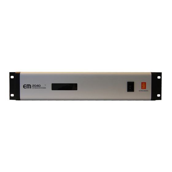
Processing unit
Hide thumbs
Also See for EM 2040:
- Installation manual (66 pages) ,
- Instruction manual (128 pages) ,
- Instruction manual (20 pages)

Related Manuals for Kongsberg EM 2040


Summary of Contents for Kongsberg EM 2040
- Page 1 KONGSBERG EM 2040 Processing Unit Installation 391932/D November 2020 © Kongsberg Maritime AS...
- Page 2 Kongsberg Maritime AS. The document, or any part of it, may not be translated to any other language without the written approval from Kongsberg Maritime AS.
-
Page 3: Table Of Contents
Clock synchronisation (1PPS) using a coax cable ..........36 Remote control .......................37 Remote Control using K-Rem ................38 Dummy plug for not using remote control .............39 K-Sync interface to EM 2040 Processing Unit ............40 Interface to Remote Control Unit for external synchronisation ......42 391932/D... - Page 4 KONGSBERG EM 2040 K-Sync interface to Remote Control Unit ..............43 Transmit transducer cable..................45 Receive transducer cable ..................47 TX to RX transducer cable ..................49 TX to dual RX transducer cable ................51 Handling of underwater connectors .................53 DRAWING FILE..............54 385422 Processing Unit dimensions................55 378828 Hydrographic Work Station dimensions .............56...
-
Page 5: About This Manual
Target audience This manual is intended for all users of the EM 2040. Due to the nature of the descriptions and the level of detail provided by this manual, it is well suited for those who are - or wish to be - expert users. -
Page 6: Kongsberg Em 2040
KONGSBERG EM 2040 Installation KONGSBERG EM 2040 Topics System description, page 7 System diagram, single system, page 8 System diagram, dual RX, page 9 System diagram, dual TX, page 10 Main system units, page 12 391932/D... -
Page 7: System Description
KONGSBERG EM 2040 System description The EM 2040 is a true wide band high resolution shallow water multibeam echo sounder. It is an ideal tool for any high resolution mapping and inspection application. Key features • Frequency range from 200 to 400 kHz •... -
Page 8: System Diagram, Single System
KONGSBERG EM 2040 Installation System diagram, single system The system diagram identifies the main components of a basic EM 2040 system. Only the main connections between the units are shown. Detailed interface capabilities and power cables are not shown. Hydrographic Work... -
Page 9: System Diagram, Dual Rx
KONGSBERG EM 2040 System diagram, dual RX The system diagram identifies the main components of a dual RX EM 2040 system. Only the main connections between the units are shown. Detailed interface capabilities and power cables are not shown. Hydrographic Work... -
Page 10: System Diagram, Dual Tx
KONGSBERG EM 2040 Installation System diagram, dual TX The system diagram identifies the main components of a dual TX EM 2040 system. Only the main connections between the units are shown. Detailed interface capabilities and power cables are not shown. - Page 11 KONGSBERG EM 2040 Hydrographic Work Station Interfaces: • Sound speed sensor • Tide • Centre depth output Processing Unit Interfaces: • Positioning systems • Attitude (roll, pitch and heave) • Sound speed sensor • Velocity • Heading • Clock • Trigger input/output •...
-
Page 12: Main System Units
Transducer description A transducer is a device that converts one form of energy to another. In an echo sounder system the transducer converts between electric energy and sound. The EM 2040 uses separate transducer arrays for transmitting and receiving sound pulses. -
Page 13: Processing Unit Description
One or two Processing Units may be required, depending on the system configuration. Portable Processing Unit description The EM 2040 Processing Unit is available in a portable splash proof IP67 rated version. The portable version has the same functionality as... -
Page 14: Portable Hydrographic Work Station Description
If you use more than one Processing Unit, a high capacity Ethernet switch is required. The Ethernet switch is used to connect each Processing Unit to the Hydrographic Work Station. A high capacity Ethernet switch is included in the EM 2040 delivery. Note It is very important that a high-quality Ethernet cable is used. - Page 15 KONGSBERG EM 2040 • One Sub-bottom profiler (SBP 27 or SBP 29) • Two EM multibeam echo sounders • One EA single beam echo sounder The Remote Control Unit is designed to be mounted in a 19 inch rack, but it is also possible to mount it on a flat surface or in a bulkhead.
-
Page 16: Cable Layout And Interconnections
Cable layout and interconnections Topics Read this first, page 17 Cable plans, page 18 List of EM 2040 cables, page 27 Installing the EM 2040 cables, page 29 Cable drawings and specifications, page 32 Handling of underwater connectors, page 53 391932/D... -
Page 17: Read This First
Kongsberg Maritime accepts no responsibility for damage to the system, or reduced operational performance, when this is caused by improper wiring. Before you install or maintain the EM 2040 cables, make sure that the AC mains circuit breaker for the system is switched off. -
Page 18: Cable Plans
KONGSBERG EM 2040 Installation Cable plans Topics Processing Unit, single system, cable plan, page 19 Processing Unit, dual RX - single swath, cable plan, page 20 Processing Unit, dual TX- single swath, cable plan, page 21 Processing Unit, dual swath, cable plan, page 23... -
Page 19: Processing Unit, Single System, Cable Plan
Cable layout and interconnections Processing Unit, single system, cable plan The Processing Unit cables include those used to connect the EM 2040 Processing Unit to AC mains power, and to the transducer. One Ethernet cable is used to connect the Processing Unit to the Hydrographic Work Station. -
Page 20: Processing Unit, Dual Rx - Single Swath, Cable Plan
KONGSBERG EM 2040 Installation Processing Unit, dual RX - single swath, cable plan The Processing Unit cables include those used to connect the EM 2040 Processing Unit to AC mains power, and to the transducer. One Ethernet cable is used to connect the Processing Unit to the Hydrographic Work Station. -
Page 21: Processing Unit, Dual Tx- Single Swath, Cable Plan
Cable layout and interconnections Processing Unit, dual TX- single swath, cable plan The Processing Unit cables include those used to connect the EM 2040 Processing Unit to AC mains power, and to the transducer. One Ethernet cable is used to connect the Processing Unit to the Hydrographic Work Station. - Page 22 KONGSBERG EM 2040 Installation Related topics List of EM 2040 cables, page 27 391932/D...
-
Page 23: Processing Unit, Dual Swath, Cable Plan
Cable layout and interconnections Processing Unit, dual swath, cable plan The Processing Unit cables include those used to connect the EM 2040 Processing Unit to AC mains power, and to the transducer. One Ethernet cable is used to connect the Processing Unit to the Hydrographic Work Station. -
Page 24: Processing Unit, Dual Rx - Dual Swath, Cable Plan
KONGSBERG EM 2040 Installation Processing Unit, dual RX - dual swath, cable plan The Processing Unit cables include those used to connect the EM 2040 Processing Units to AC mains power, and to the transducer. Ethernet cables are used to connect the Processing Units to the Hydrographic Work Station. - Page 25 Processing Unit (PU), slave Transmit Transducer (TX) Receive Transducer (RX) Ethernet switch Cables identified with an asterisk (*) are system cables. These cables are supplied with the EM 2040 delivery. Related topics List of EM 2040 cables, page 27 391932/D...
-
Page 26: Cable Plan, Hydrographic Work Station
KONGSBERG EM 2040 Installation Cable plan, Hydrographic Work Station The topside/bridge cables include those used to connect the EM 2040 Hydrographic Work Station and the display to each other, to AC mains power, and to external devices. Hydrographic Work Station Display The Hydrographic Work Station supports up to three displays. -
Page 27: List Of Em 2040 Cables
Cable layout and interconnections List of EM 2040 cables A set of cables is required to connect the EM 2040 units to each other, and to the relevant power source(s). Cable Signal From/To Minimum requirements Video cable From Hydrographic Work Station to display This is a commercial cable. - Page 28 STP (Shielded Twisted Pair) quality or better. If you use cables with lower bandwidth capacity you will reduce the EM 2040 performance. The EM 2040 is often a part of a project delivery. For such deliveries, specific project cable drawings are established to show all the main cables, and how the various products are connected.
-
Page 29: Installing The Em 2040 Cables
The connector is RJ45 type. Local connection The connector is RJ45 type. Note Pin 3 and 6 is used by Kongsberg Maritime only. Connection on remote device Unless otherwise specified, this cable must be provided by the installation shipyard. -
Page 30: Hydrographic Work Station Rear Connectors
It is very important that high-quality Ethernet cables are used. You must use CAT-5E STP (Shielded Twisted Pair) quality or better. If you use cables with lower bandwidth capacity you will reduce the EM 2040 performance. Display port Display cable: From Hydrographic Work Station to display (C1) This is a commercial cable. - Page 31 Cable layout and interconnections Computer cable: From Hydrographic Work Station to keyboard (C3) The cable is often physically attached to the keyboard, and terminated in the “computer end” with a male PS/2 or USB connector. Depending on the type of connector you must connect the keyboard to the PS/2 connector or an USB connector on the computer.
-
Page 32: Cable Drawings And Specifications
Remote Control using K-Rem, page 38 Dummy plug for not using remote control, page 39 K-Sync interface to EM 2040 Processing Unit, page 40 Interface to Remote Control Unit for external synchronisation, page 42 K-Sync interface to Remote Control Unit, page 43... -
Page 33: Rs-232 Serial Line Using Three Wires And Rj45 Connector
Cable layout and interconnections RS-232 serial line using three wires and RJ45 connector An RS-232 serial line connection using three (3) wires is a common way to connect the EM 2040 to external devices. Local connection RJ45 connector Connection on remote device... -
Page 34: Rs-422 Serial Line Using Five Wires And Rj45 Connector
RS-422 serial line using five wires and RJ45 connector An RS-422 serial line connection is a common way to connect the EM 2040 to external devices. An RS-422 serial line connection can transmit data at rates as high as 10 million bits per second, and may be sent on cables as long as 1500 meters. -
Page 35: Adapter For D-Connector To Rj45 Connector For Rs-422
Cable layout and interconnections Adapter for D-connector to RJ45 connector for RS-422 You can use an adapter if you need to connect a serial cable with a D-connector to the Processing Unit. The Processing Unit has four serial ports with RJ45 connectors. The ports can be configured to be RS-232 or RS-422. -
Page 36: Clock Synchronisation (1Pps) Using A Coax Cable
KONGSBERG EM 2040 Installation Clock synchronisation (1PPS) using a coax cable The Processing Unit is equipped with a 1PPS signal input for clock synchronisation. Male BNC connector Ground 1PPS signal This cable must be provided by the installation shipyard. The 1PPS (one pulse per second) signal is normally provided by a positioning system. -
Page 37: Remote Control
Cable layout and interconnections Remote control The Processing Unit can be switched on/off with a remote switch. This switch is connected to a 9–pin D-connector on the Processing Unit. Local connection, male 9–pin D-connector Connection to remote lamp and on/off switch Female 9–pin D-connector Male 9–pin D-connector Minimum cable requirements... -
Page 38: Remote Control Using K-Rem
KONGSBERG EM 2040 Installation Remote Control using K-Rem The Processing Unit can be switched on/off with a remote switch. This switch is connected to a 9–pin D-connector on the Processing Unit. A dedicated junction box with on/off switches and light indication has been designed for this purpose (K-Rem). -
Page 39: Dummy Plug For Not Using Remote Control
Cable layout and interconnections Dummy plug for not using remote control The Processing Unit can be switched on/off with a remote switch. If remote control is not used, the enclosed remote control dummy plug has to be inserted in the Remote Control connector in the Processing Unit. -
Page 40: K-Sync Interface To Em 2040 Processing Unit
The connector is RJ45 type. This cable must be provided by the installation shipyard. Connections on the EM 2040 Processing Unit. RJ45 connector Note Pin 3 and 6 is used by Kongsberg Maritime only. - Page 41 Cable layout and interconnections Each IO Module in the K-Sync Synchronizing Unit provides six connectors and a configuration board for physical adjustments of the communication parameters. Connectors 1 through 6 as indicated by the arrows. Note that each of the two connector elements can be pulled out of the IO Module for easy access.
-
Page 42: Interface To Remote Control Unit For External Synchronisation
Pin 3 and 6 is used by Kongsberg Maritime only. Connections in the Remote Control Unit (K-Rem) Unless otherwise specified, this cable must be provided by the installation shipyard. The Remote Control Unit is not a standard part of the EM 2040 delivery. Minimum cable requirements •... -
Page 43: K-Sync Interface To Remote Control Unit
The Remote Control Unit is called K-Rem. It is prepared for remote control and interface to an external synchronization system for four KONGSBERG echo sounders. Connections in the Remote Control Unit (K-Rem) - Page 44 IO Module for easy access. Configuration board Unless otherwise specified, this cable must be provided by the installation shipyard. The Remote Control Unit is not a standard part of the EM 2040 delivery. Minimum cable requirements • : 2 x 5 x 0.5 mm Conductors •...
-
Page 45: Transmit Transducer Cable
Cable layout and interconnections Transmit transducer cable The TX transducer must be connected to the Processing Unit. 391932/D... - Page 46 Sacrificial anodes must be mounted near the transducer to protect the connectors. Inspect the anodes regularly, and replace them if needed. Correct handling of the underwater connectors is very important to avoid any leakage and corrosion problems to the EM 2040 transducers. Related topics Handling of underwater connectors, page 53...
-
Page 47: Receive Transducer Cable
The RX transducer must be connected to the Processing Unit. Note A change in the cable wiring was effectuated without KONGSBERG being made aware. As a consequence there are currently two versions of the cable delivered that have the same part number. This change was introduced to the cable in Q2 2011. Please make sure to check the connections in your RJ45 connector against the drawings below before replacing it. - Page 48 Sacrificial anodes must be mounted near the transducer to protect the connectors. Inspect the anodes regularly, and replace them if needed. Correct handling of the underwater connectors is very important to avoid any leakage and corrosion problems to the EM 2040 transducers. Related topics Handling of underwater connectors, page 53...
-
Page 49: Tx To Rx Transducer Cable
Cable layout and interconnections TX to RX transducer cable The transmit transducer must be connected to the receive transducer for synchronization and power. Connector in TX end. Face view. Connector in RX end. Face view. 391932/D... - Page 50 Sacrificial anodes must be mounted near the transducer to protect the connectors. Inspect the anodes regularly, and replace them if needed. Correct handling of the underwater connectors is very important to avoid any leakage and corrosion problems to the EM 2040 transducers. Related topics Handling of underwater connectors, page 53...
-
Page 51: Tx To Dual Rx Transducer Cable
Cable layout and interconnections TX to dual RX transducer cable In a dual RX system, the transmit transducer must be connected to both receive transducers. This connection is for synchronization and power. 391932/D... - Page 52 Sacrificial anodes must be mounted near the transducer to protect the connectors. Inspect the anodes regularly, and replace them if needed. Correct handling of the underwater connectors is very important to avoid any leakage and corrosion problems to the EM 2040 transducers. Related topics Handling of underwater connectors, page 53...
-
Page 53: Handling Of Underwater Connectors
Cable layout and interconnections Handling of underwater connectors Correct handling of the underwater connectors is very important to avoid any leakage and corrosion problems to the EM 2040 transducers. Important You must follow these instructions carefully to ensure correct use of your SubConn ®... -
Page 54: Drawing File
KONGSBERG EM 2040 Installation Drawing file Topics 385422 Processing Unit dimensions, page 55 378828 Hydrographic Work Station dimensions, page 56 370275 Remote Control Unit (K-REM) dimensions, page 58 373962 Remote Control Unit (K-REM) wiring diagram, page 60 391932/D... -
Page 55: 385422 Processing Unit Dimensions
Drawing file 385422 Processing Unit dimensions 391932/D... -
Page 56: 378828 Hydrographic Work Station Dimensions
KONGSBERG EM 2040 Installation 378828 Hydrographic Work Station dimensions 391932/D... - Page 57 Drawing file 391932/D...
-
Page 58: 370275 Remote Control Unit (K-Rem) Dimensions
KONGSBERG EM 2040 Installation 370275 Remote Control Unit (K-REM) dimensions 391932/D... - Page 59 Drawing file 391932/D...
-
Page 60: 373962 Remote Control Unit (K-Rem) Wiring Diagram
KONGSBERG EM 2040 Installation 373962 Remote Control Unit (K-REM) wiring diagram 391932/D... -
Page 61: Technical Specifications
Technical specifications Technical specifications Topics Performance specifications, page 62 Interface specifications, page 65 Weight and outline dimensions, page 73 Power requirements, page 76 Environmental requirements, page 79 Alignment specifications, page 81 391932/D... -
Page 62: Performance Specifications
KONGSBERG EM 2040 Installation Performance specifications These performance specifications summarize the main functional and operational characteristics of the EM 2040 system. • : 200 to 400 kHz Frequency range • Selectable frequencies – : 200, 300 and 400 kHz operating mode Single system and dual RX –... - Page 63 Depth and coverage (Maximum) Cold ocean water, bottom type rock (BS = - 10 dB), NL = 45 dB, FM mode Operating mode Max depth Max coverage across EM 2040-04 Single RX Dual RX 200 kHz 635 m 920 m...
- Page 64 KONGSBERG EM 2040 Installation • Pulse length, CW – : Hanning Pulse shading – : 37 to 865 μs Total pulse length – : 25 to 600 μs Nominal pulse length – : 14 to 324 μs (BS footprint) Effective pulse length •...
-
Page 65: Interface Specifications
• Any future EM multibeams The KM multibeam output datagram format is described in a Doxygen document, a documentation generator writing software reference documentation, and can be downloaded from the Kongsberg websites. See this page to download the Doxygen document: https://www.kongsberg.com/mar- itime/support/document-and-downloads/software-downloads/. -
Page 66: Interface Specifications - Processing Unit - All Format
• EM 2040 Series multibeams • EM 712 For these KONGSBERG will continue to do maintenance and bug fixing for all and SIS4. Any new feature development will only be available for KMall and SIS5. Upgrading to the new format, K-Controller and SIS5 is free, but new features might be licensed. - Page 67 The NMEA ZDA datagram contains the universal time code (UTC), day, month, year and local time zone. Supported datagram formats for heading information The EM 2040 supports the following datagram formats for vessel heading and/or gyro information. These datagram formats are received using a serial communication line.
- Page 68 KONGSBERG EM 2040 Installation Supported datagram formats for motion information The EM 2040 system supports the following datagram format from a motion sensor: These datagram formats are received using a serial communication line. • Kongsberg EM Attitude 3000 The Kongsberg EM Attitude 3000 is a proprietary datagram format created by Kongsberg Maritime for use with digital motion sensors.
-
Page 69: Interface Specifications - Processing Unit - Kmall Format
Technical specifications Interface specifications - Processing Unit - KMall format The EM 2040 system will interface with peripheral systems and sensors using standard and/or proprietary datagram formats. This is a description of available datagram formats for EM multibeams using the KMall format. - Page 70 Sound speed probe can be interfaced directly to the Processing Unit and configured in K-Controller or interfaced to the Hydrograpic Work Station and configured in SIS 5. The EM 2040 supports the following datagram format from a sound speed probe. •...
-
Page 71: External Sensors Requirements
In the FM mode, the Doppler shift made by the movements of the survey vessel relative to the bottom, causes a range error. This error must be corrected. KONGSBERG supports a large range of sensor suppliers in addition to our own Kongsberg Seatex systems. -
Page 72: Interface Specifications - Hydrographic Work Station - All Format
Interface specifications - Hydrographic Work Station - all format The EM 2040 system will interface with peripheral systems and sensors using standard and/or proprietary datagram formats. This is a description of available datagram formats for EM multibeams using the all format. -
Page 73: Weight And Outline Dimensions
Technical specifications Weight and outline dimensions These weights and outline dimension characteristics summarize the physical properties of the EM 2040 system. Transmit transducer - 0.4 degrees • Outline dimensions – : 725 mm Length – : 200 mm Width –... - Page 74 KONGSBERG EM 2040 Installation Transducer mounting plate, 0.4 degrees • Outline dimensions – : 615 mm Length – : 725 mm Width – : 139 mm including support pillars Height • : 23 kg Weight Transducer mounting plate, 0.7 degrees •...
- Page 75 Technical specifications Hydrographic Work Station The standard commercial computer has been configured to fit the operational requirements of the EM 2040. • : HP MP5810 Make and model • Outline dimensions – : 379 mm Depth – : 338 mm Width –...
-
Page 76: Power Requirements
KONGSBERG EM 2040 Installation Power requirements These power characteristics summarize the supply power requirements for the EM 2040 system. Transducer The power is normally supplied by the Processing Unit. • : 48 VDC Voltage requirement • : 10 % Maximum voltage deviation •... - Page 77 • Dual RX Head Dual Swath systems require two processing units with two CBMF cards in each processing unit Dual Head Dual Swath systems are not available for the Portable Processing Unit. System calculation examples EM 2040 0.7x0.7 degrees Dual RX - Single Swath System Maximum power consumption Component Processing unit with 2xCBMF EM 2040 0.7 degrees Receiver...
- Page 78 KONGSBERG EM 2040 Installation EM 2040 0.4x0.7 degrees Dual RX - Dual Swath System Maximum power consumption Component Processing unit with 2xCBMF Processing unit with 2xCBMF EM 2040 0.7 degrees Receiver EM 2040 0.7 degrees Receiver EM 2040 0.4 degrees Transmitter...
-
Page 79: Environmental Requirements
Optional • : 40 W Maximum power consumption Environmental requirements These specifications summarize the temperature requirements and other environmental standards for the EM 2040 system. Transducer • : -5 to +40 °C Operating temperature • : -20 to +60 °C Storage temperature •... - Page 80 Designed to meet – IEC 60945:2002 and CORRIGENDUM 1:2008 – IACS E10:2006 Hydrographic Work Station The standard commercial computer has been configured to fit the operational requirements of the EM 2040. • : HP MP5810 Make and model • : 0 to +50 °C Operating temperature •...
-
Page 81: Alignment Specifications
– IEC 60945 – IACS E10 Alignment specifications These alignment specifications summarize the alignment accuracy requirements of the EM 2040 system. Note The following accuracy requirements are minimum requirements. Higher accuracy will provide better results and should therefore always be aimed at. - Page 82 KONGSBERG EM 2040 Installation Note : 90 degrees ± 1 degrees Mounting angle between RX and TX transducer Motion sensor alignment accuracy • : ± 0.05 m Position (x) • : ± 0.05 m Position (y) • : ± 0.05 m Position (z) •...
- Page 83 Index Index 1PPS cable specifications clock synchronisation ........36 RS-232 ............ 33 connection ..........36 RS-422 ............ 34 cables list of system interconnection cables ....27 read this first ..........17 RX transducer ..........47 about TX to dual RX transducer ......51 document downloads ........
- Page 84 KONGSBERG EM 2040 Installation Portable Hydrographic Work Station ....14 system ............7 GPS information dimensions datagram formats ........66, 69 computer outline dimensions drawing ....56 gyro information display ............. 75 datagram formats ........67 Hydrographic Work Station ......75 Hydrographic Work Station outline dimensions drawing ..........
- Page 85 Index outline dimensions........75 Ethernet switch........... 14 power requirements........79 Hydrographic Work Station ......13 weight ............. 75 Portable Hydrographic Work Station ....14 list system interconnection cables......27 performance specifications ..........62 mains power peripheral systems requirements ..........76 interface specifications ......
- Page 86 KONGSBERG EM 2040 Installation power requirements........76 display ............. 75 weight ............. 74 Hydrographic Work Station ......75 publication Hydrographic Work Station outline purpose ............. 5 dimensions ..........56 target audience ..........5 Portable Processing Unit........ 74 purpose Processing Unit .......... 74 computer ..........
- Page 87 Index interface specifications ......66, 69 wiring outline dimensions........73 list of system interconnection cables ....27 RX transducer cable ........47 wiring diagram TX to dual RX transducer cable ....... 51 Hydrographic Work Station ......26 TX to RX transducer cable ......49 processing unit ......
- Page 88 ©2020 Kongsberg Maritime...
Need help?
Do you have a question about the EM 2040 and is the answer not in the manual?
Questions and answers