Table of Contents
Advertisement
Quick Links
Advertisement
Table of Contents

Related Manuals for Gefen EXT-DVIK-MV-41


Summary of Contents for Gefen EXT-DVIK-MV-41
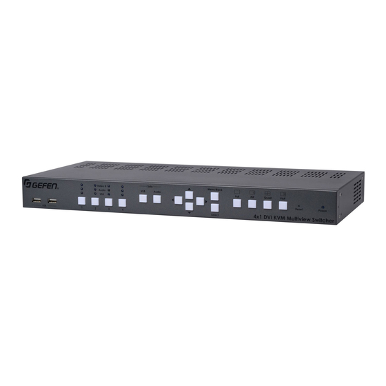
- Page 1 *Preferred 4x1 DVI KVM Multiview Switcher EXT-DVIK-MV-441 User Manual Release A3...
- Page 2 Important Safety Instructions Read these instructions. Keep these instructions. Heed all warnings. Follow all instructions. Do not use this unit near water. Clean only with a dry cloth. Do not block any ventilation openings. Install in accordance with the manufacturer’s instructions.
- Page 3 Gefen warrants the equipment it manufactures to be free from defects in material and workmanship. If equipment fails because of such defects and Gefen is notified within two (2) years from the date of shipment, Gefen will, at its option, repair or replace the equipment, provided that the equipment has not been subjected to mechanical, electrical, or other abuse or modifications.
- Page 4 Technical Support (818) 772-9100 (800) 545-6900 8:00 AM to 5:00 PM Monday - Friday, Pacific Time (818) 772-9120 Email support@gefen.com http://www.gefen.com Mailing Address Gefen, LLC c/o Customer Service 20600 Nordhoff St. Chatsworth, CA 91311 Product Registration Register your product here: http://www.gefen.com/kvm/Registry/Registration.jsp...
- Page 5 4x1 DVI KVM Multiview Switcher is a trademark of Gefen, LLC. © 2015 Gefen, LLC. All Rights Reserved. All trademarks are the property of their respective owners. Gefen, LLC reserves the right to make changes in the hardware, packaging, and any accompanying documentation without prior written notice.
- Page 6 Packing List The 4x1 DVI KVM Multiview Switcher ships with the items listed below. If any of these items are not present in the box when you first open it, immediately contact your dealer or Gefen. • 1 x 4x1 DVI KVM Multiview Switcher •...
- Page 7 This page left intentionally blank.
-
Page 8: Table Of Contents
Table of Contents Getting Started Introduction......................2 Front Panel ....................2 Back Panel ....................4 Installation ......................7 Connection Instructions ................. 7 Sample Wiring Diagram ................9 Basic Operation Powering the Switcher..................12 Display Nomenclature ..................14 Main and Auxiliary Displays ................ 14 Using the Auxiliary Display ................ - Page 9 Table of Contents Read Monitor EDID ..................68 Upgrade Firmware ..................70 Changing the Source Name ................ 71 Cascading ......................73 Advanced Operation RS-232 Interface ....................80 RS-232 Interface ..................80 RS-232 Settings ..................80 Commands ......................81 Appendix Default Settings ....................114 OSD ......................
- Page 10 This page left intentionally blank.
-
Page 11: Getting Started
4x1 DVI KVM Multiview Switcher Getting Started... -
Page 12: Introduction
Introduction Page Title page | 2... - Page 13 Introduction Page Title Name Description Connect a USB device to each of these USB ports. Source selection (1 - 4) Press these buttons to select the video / audio / USB source. Switching Sources (page 19) more information. Solo (USB, Audio) These buttons allow separate (unlinked) selection of USB an audio sources.
-
Page 14: Back Panel
Introduction page | 4... - Page 15 Introduction Name Description Grounding terminal Connect a grounding wire from this terminal to an approved Earth ground. Main Press this switch to power-on or power- off the unit. 12V DC Connect the included power supply from this power receptacle to an available electrical outlet.
- Page 16 Introduction Name Description USB Host Use USB cables to connect up to four (Source 1 - Source 4) computers to these USB ports. DVI-D In Connect up to four computer sources to (Source 1 - Source 4) these ports using DVI cables. page | 6...
-
Page 17: Installation
Installation Menu/Back Full Quad Connection Instructions Reset Power Video Source ► 4x1 DVI KVM Multiview Switcher Select Use DVI cables to connect a DVI source (e.g. computer) to each one of the DVI-D In ports (Source 1 - Source 4) on the rear panel. Note that only DVI-D (digital) sources are supported. - Page 18 10. Connect the included power supply to the 12V DC power receptacle on the 4x1 DVI KVM Multiview Switcher. 11. Connect the included AC cable from the power receptacle to an available electrical outlet. EXT-DVIK-MV-41 EXT-DVIK-MV-41 Keyboar Video A D...
-
Page 19: Sample Wiring Diagram
Installation Sample Wiring Diagram RS-232 CABLE USB CABLE 3.5mm MINI-STEREO CABLE Daisy-Chain MIC CABLE to a second DVI CABLE EXT-DVIK-MV-41’s RS-232 In RS-232 Automation Control Device Multimedia PC/Servers RS-232 RS-232 Powered Speakers DVI Display EXT-DVIK-MV-41 DVI KVM Multiview Switcher Mouse... - Page 20 This page left intentionally blank.
-
Page 21: Basic Operation
4x1 DVI KVM Multiview Switcher Basic Operation... -
Page 22: Powering The Switcher
Installation (page Video B ® Audio DVI Displays Computer Sources EXT-DVIK-MV-41 Keyboard / Mouse DVI KVM Multiview Switcher Press the Main (power) button on the back panel so that the top-portion, marked with an “I”, is flush with the back panel... - Page 23 (Source 1, by default) will be shown on the display connected to Video B. DVI Displays Computer Sources Keyboard / Mouse EXT-DVIK-MV-41 DVI KVM Multiview Switcher The window layout for Quad mode, on Video A, is arranged as follows: Solo...
-
Page 24: Display Nomenclature
Solo Menu/Back Audio Display Nomenclature Full Quad 4x1 DVI Main and Auxiliary Displays Select The 4x1 DVI KVM Multiview Switcher uses has two output ports on the rear panel: Video A and Video B. The Video A port is used to display the video modes (Full, PIP, Quad, and PAP) and is referred to as the main display. -
Page 25: Using The Auxiliary Display
PIP mode and the Source 1 button is currently selected. Source 1 is displayed on the auxiliary display (Video B). DVI Displays Computer Sources EXT-DVIK-MV-41 DVI KVM Multiview Switcher Now, we’ll switch to Source 2. As expected, Source 2 is now displayed on the auxiliary display (Video B). -
Page 26: Windows
Audio ® Audio Full Quad Reset Power 4x1 DVI KVM Multiview Switcher Select EXT-DVIK-MV-41 Keyboard Mouse Mic L/R Out L/R In USB Host L/R In USB Host L/R In USB Host L/R In USB Host Video A DVI-D Video B DVI-D... -
Page 27: Display Modes
Display Modes The Video A port on the 4x1 DVI KVM Multiview Switcher provides the ability to display up to four DVI sources, simultaneously. The 4x1 DVI KVM Multiview Switcher comes with 4 display modes: Full, PIP (Picture-In-Picture), Quad, and PAP (Picture-And-Picture). Full Displays a full-screen image of the selected source (1 - 4). -
Page 28: Selecting The Display Mode
Display Modes Selecting the Display Mode The 4x1 DVI KVM Multiview Switcher comes with 4 display modes. Of these 4 display modes, both PIP and PAP display modes allow you to switch the main window to a subordinate window. In the case of PIP mode, the subordinate window can be repositioned to any location on the display and can be re-sized, if desired. -
Page 29: Switching Sources
Switching Sources Switching sources can be accomplished by using the Source buttons on the front panel, the mouse, function keys, or using predefined hot-key bindings. Hotkey assignments can be user-defined as needed. In order to operate the Switcher using a mouse, a 3-button mouse is required. - Page 30 Switching Sources The currently selected source will be indicated by a “dash”, as shown: Current source Left click the desired input (1 - 4) from the drop-down menu. The selected source will be shown on both Video A and Video B. Click the middle mouse button / wheel to dismiss the Display Mode menu.
- Page 31 Switching Sources ► Press the following keys, in sequence, on the computer keyboard. The default hotkey is the Scroll Lock key. To reassign the hotkey refer to Defining the Hotkey (page 40) for more information. hotkey hotkey Space Bar The OSD will be displayed. Select Input Name...
-
Page 32: Pip (Picture-In-Picture) Mode
Switching Sources PIP (Picture-In-Picture) Mode ► Front panel Press the PIP button to enter PIP mode. Press the desired source button (1 - 4). The selected source will be shown on both Video B and in the main window on Video A. Solo Menu/Back Solo... - Page 33 Switching Sources ► Mouse Click the middle mouse button / wheel to display the mode menu on the Video A display. Left-click the PIP mode icon. A drop-down menu will be displayed. The drop-down menu will be separated into two panels, as shown. The top panel controls the main window.
- Page 34 Switching Sources Left click the desired input (1 - 4) from the drop-down menu for the main window on Video A. The selected source will also be displayed on Video Left click the desired input (1 - 4) from the drop-down menu for the subordinate window on Video A.
- Page 35 Switching Sources ► Press the following keys, in sequence, on the computer keyboard. The default hotkey is the Scroll Lock key. To reassign the hotkey refer to Defining the Hotkey (page 40) for more information. hotkey hotkey Space Bar The OSD will be displayed. Select Input Name...
-
Page 36: Quad Mode
Switching Sources Quad Mode Quad mode allows four all sources (Source 1 - Source 4) to be displayed on Video A. The order and size of each window cannot be changed. Each window is associated with a source: Window 1 = Source 1, Window 2 = Source 2, and so on. Source 1 Source 2 Source 3... - Page 37 Switching Sources ► Front panel Press the Quad button. Press the desired source button (1 - 4). The selected source will be displayed on both Video B and in the associated window of Video A. Solo Menu/Back Solo Menu/Back Video B Video B Audio Audio...
- Page 38 Switching Sources The currently selected source, for each window, will be indicated by a “dash”, as shown: Current source Left click the desired input (1 - 4) from the drop-down menu. The selected source will also be displayed on both Video B and in the associated window in Video A.
- Page 39 Switching Sources ► Press the following keys, in sequence, on the computer keyboard. The default hotkey is the Scroll Lock key. To reassign the hotkey refer to Defining the Hotkey (page 40) for more information. hotkey hotkey Space Bar The OSD will be displayed. Select Input Name...
-
Page 40: Pap (Picture-And-Picture) Mode
Switching Sources PAP (Picture-And-Picture) Mode ► Front panel Press the PAP button. Press the desired source button (1 - 4). The selected source will be displayed on both Video B and in the main window of Video A. The subordinate windows will display the remaining sources. - Page 41 Switching Sources The currently selected source for the main window will be indicated by a “dash”, as shown. Current source Left click the desired input (1 - 4) from the drop-down menu. The selected source will also be displayed on both Video B and in the associated window in Video A.
- Page 42 Switching Sources ► Press the following keys, in sequence, on the computer keyboard. The default hotkey is the Scroll Lock key. To reassign the hotkey refer to Defining the Hotkey (page 40) for more information. hotkey hotkey Space Bar The OSD will be displayed. Select Input Name...
-
Page 43: Solo Buttons
Solo Buttons Information The Solo USB and Audio buttons are used only to temporarily switch between devices. To unlink devices from one another, use the OSD, RS-232, or #link hotkeys. Refer to Linking / Unlinking USB (page 42), the #unlink commands, and Hotkeys (page 115). -
Page 44: Independent Audio Switching
Solo Buttons To exit solo USB mode, press the USB button again. The USB button will turn off and the USB device will re-link with the currently selected Video B source. Solo Menu/Back Solo Menu/Back eo B Video B Audio Audio ®... - Page 45 Solo Buttons Solo Solo Menu/Back Menu/Back Video B Audio Audio Audio Full Quad Full Quad Reset Power 4x1 DVI KVM Multiview Switch 4x1 DVI KV Select Select To exit solo audio mode, press the Audio button again. The Audio button will turn off and the audio device will re-link with the currently selected Video B source.
-
Page 46: Pip & Pap Modes
PIP & PAP Modes This section discusses some functions that are unique to PIP (Picture-In-Picture) and PAP (Picture-And-Picture) modes. Zoom and Position (PIP Only) Enter PIP mode and set the main and subordinate windows with the desired sources. Click the middle mouse button / wheel to display the Mode menu. Place the mouse cursor over the subordinate window. -
Page 47: Window Management In Pap Mode
PIP & PAP Modes To zoom-in or zoom-out of the subordinate window, use the scroll wheel on the mouse. Make sure that the mouse cursor is placed over the subordinate window before zooming. Note that the zoom-in and zoom-out direction (scroll up or scroll down) will depend upon the scroll settings of the mouse. - Page 48 PIP & PAP Modes Pressing the Source 2 button swaps window 1 with window 2: Pressing the Source 4 button swaps window 2 with window 4: Finally, if we wanted Source 1 back in the main window, we would press the Source 1 button, which would swap window 4 with window 1.
-
Page 49: Osd Menu
OSD Menu Accessing the Menu System The 4x1 DVI KVM Multiview Switcher uses a built-in menu system to manage and control all video features. Access the menu system using the following keystrokes: The default hotkey is the Scroll Lock key. To reassign the hotkey refer to Defining the Hotkey (page 40) for more information. -
Page 50: Defining The Hotkey
OSD Menu Defining the Hotkey The default hotkey is the Scroll Lock key. However, the hotkey assignment can be changed. The Scroll Lock key is used in the following procedure. To access the menu system, use the following keystrokes: Scroll Lock Scroll Lock Space Bar Select the Settings option using the ▲... - Page 51 OSD Menu Select the desired hotkey using the ◄ or ► keys on the computer keyboard. The available selections are: Scroll, Caps, NumLock, L Ctrl, or R Ctrl. Once the desired hotkey has been selected, press the Esc key. The following message will be displayed: Save Before Exit? Back Press the Enter key to select the Yes option and save the changes.
-
Page 52: Linking / Unlinking Usb
OSD Menu Linking / Unlinking USB Enter the menu system. See Accessing the Menu System (page 39) for more information. Select the Settings option using the ▲ or ▼ keys on the computer keyboard. Select Input Name VID USB AUD USB VID-A VID-B PIP PC01 AUD USB VID-A VID-B PC02... - Page 53 OSD Menu Select the desired option by using the ◄ or ► keys. If the Link USB is set to Yes, then the USB will follow the source when switching. If the Link USB is set to No, then the USB can be routed independently of the currently selected source.
-
Page 54: Linking / Unlinking Audio
OSD Menu Linking / Unlinking Audio Enter the menu system. See Accessing the Menu System (page 39) for more information. Select the Settings option using the ▲ or ▼ keys on the computer keyboard. Select Input Name VID USB AUD USB VID-A VID-B PIP PC01 AUD USB VID-A VID-B PC02... - Page 55 OSD Menu Select the desired option by using the ◄ or ► keys. If the Link Audio is set to Yes, then the Audio will follow the source when switching. If the Link Audio is set to No, then the Audio can be routed independently of the currently selected source.
-
Page 56: Linking / Unlinking Video B
OSD Menu Linking / Unlinking Video B Enter the menu system. See Accessing the Menu System (page 39) for more information. Select the Settings option using the ▲ or ▼ keys on the computer keyboard. Select Input Name VID USB AUD USB VID-A VID-B PIP PC01 AUD USB VID-A VID-B... - Page 57 OSD Menu Select the desired option by using the ◄ or ► keys. If the Link Video B is set to Yes, then the display connected to Video B will always show the currently selected source. This is the default setting. If the Link Video B is set to No, then this will allow each display (Video A and Video B) to show a different source.
-
Page 58: Osd Timeout
OSD Menu OSD Timeout Enter the menu system. See Accessing the Menu System (page 39) for more information. Select the Settings option using the ▲ or ▼ keys on the computer keyboard. Select Input Name VID USB AUD USB VID-A VID-B PIP PC01 AUD USB VID-A VID-B PC02... - Page 59 OSD Menu Select the desired timeout by using the ◄ or ► keys. The timeout can be set to one of the following values, in seconds: 0, 5, 10, 15, 20, 25, 30, 40, 50, or 60. To keep the OSD displayed at all times, set the OSD Timeout value to 0 seconds.
-
Page 60: Titlebar Timeout
OSD Menu Titlebar Timeout Enter the menu system. See Accessing the Menu System (page 39) for more information. Select the Settings option using the ▲ or ▼ keys on the computer keyboard. Select Input Name VID USB AUD USB VID-A VID-B PIP PC01 AUD USB VID-A VID-B PC02... - Page 61 OSD Menu Select the desired timeout by using the ◄ or ► keys. The timeout can be set to one of the following values, in seconds: 0, 5, 10, 15, 20, 25, 30, or OFF. To keep the titlebar displayed at all times, set the Titlebar Timeout value to 0 seconds.
-
Page 62: Show Pc Name
OSD Menu Show PC Name Enter the menu system. See Accessing the Menu System (page 39) for more information. Select the Settings option using the ▲ or ▼ keys on the computer keyboard. Select Input Name VID USB AUD USB VID-A VID-B PIP PC01 AUD USB VID-A VID-B PC02... - Page 63 OSD Menu Select the desired option by using the ◄ or ► keys. If the Show PC Name is set to Yes, then the name of the PC will be displayed above the current input resolution. This is the default setting. If the Show PC Name is set to No, then only the input resolution will be displayed.
-
Page 64: Show Video Signal
OSD Menu Show Video Signal Enter the menu system. See Accessing the Menu System (page 39) for more information. Select the Settings option using the ▲ or ▼ keys on the computer keyboard. Select Input Name VID USB AUD USB VID-A VID-B PIP PC01 AUD USB VID-A VID-B PC02... - Page 65 OSD Menu Select the desired option by using the ◄ or ► keys. If the Show Video Signal is set to Yes, then the current input resolution will be displayed below the current PC name. This is the default setting. If the Show Video Signal is set to No, then only the PC name will be displayed.
-
Page 66: Output Resolution
OSD Menu Output Resolution Enter the menu system. See Accessing the Menu System (page 39) for more information. Select the Settings option using the ▲ or ▼ keys on the computer keyboard. Select Input Name VID USB AUD USB VID-A VID-B PIP PC01 AUD USB VID-A VID-B PC02... - Page 67 OSD Menu Use the ▲ or ▼ keys to select the Output Resolution option. Previous Page Output Resolution 1280x1024 Shrink Control Keep Ratio EDID Mode External OneClick Switching Wheel PIP Scan Period Load Factory Default Main Menu Information Exit Settings Full view Exit PIP view...
-
Page 68: Shrink Control
OSD Menu Shrink Control Enter the menu system. See Accessing the Menu System (page 39) for more information. Select the Settings option using the ▲ or ▼ keys on the computer keyboard. Select Input Name VID USB AUD USB VID-A VID-B PIP PC01 AUD USB VID-A VID-B PC02... - Page 69 OSD Menu Use the ▲ or ▼ keys to select the Shrink Control option. Previous Page Output Resolution 1280x1024 Shrink Control Keep Ratio EDID Mode External OneClick Switching Wheel PIP Scan Period Load Factory Default Main Menu Information Exit Settings Full view Exit PIP view...
-
Page 70: Edid Mode
OSD Menu EDID Mode Enter the menu system. See Accessing the Menu System (page 39) for more information. Select the Settings option using the ▲ or ▼ keys on the computer keyboard. Select Input Name VID USB AUD USB VID-A VID-B PIP PC01 AUD USB VID-A VID-B PC02... - Page 71 OSD Menu Use the ▲ or ▼ keys to select the EDID Control option. Previous Page Output Resolution 1280x1024 Shrink Control Keep Ratio EDID Mode External OneClick Switching Wheel PIP Scan Period Load Factory Default Main Menu Information Exit Settings Full view Exit PIP view...
-
Page 72: One-Click Switching
OSD Menu One-Click Switching Enter the menu system. See Accessing the Menu System (page 39) for more information. Select the Settings option using the ▲ or ▼ keys on the computer keyboard. Select Input Name VID USB AUD USB VID-A VID-B PIP PC01 AUD USB VID-A VID-B PC02... - Page 73 OSD Menu Use the ▲ or ▼ keys to select the One-Click Switching option. Previous Page Output Resolution 1280x1024 Shrink Control Keep Ratio EDID Mode 1080P OneClick Switching Wheel PIP Scan Period Load Factory Default Main Menu Information Exit Settings Full view Exit PIP view...
-
Page 74: Pip Scan Period
OSD Menu PIP Scan Period Enter the menu system. See Accessing the Menu System (page 39) for more information. Select the Settings option using the ▲ or ▼ keys on the computer keyboard. Select Input Name VID USB AUD USB VID-A VID-B PIP PC01 AUD USB VID-A VID-B PC02... - Page 75 OSD Menu Use the ▲ or ▼ keys to select the PIP Scan Period option. Previous Page Output Resolution 1280x1024 Shrink Control Keep Ratio EDID Mode 1080P OneClick Switching Wheel PIP Scan Period Load Factory Default Main Menu Information Exit Settings Full view Exit...
-
Page 76: Load Factory Default
OSD Menu Load Factory Default Enter the menu system. See Accessing the Menu System (page 39) for more information. Select the Settings option using the ▲ or ▼ keys on the computer keyboard. Select Input Name VID USB AUD USB VID-A VID-B PIP PC01 AUD USB VID-A VID-B PC02... - Page 77 OSD Menu Use the ▲ or ▼ keys to select the Load Factory Default option. Previous Page Output Resolution 1280x1024 Shrink Control Keep Ratio EDID Mode 1080P OneClick Switching Wheel PIP Scan Period Load Factory Default Main Menu Information Exit Settings Full view Exit...
-
Page 78: Read Monitor Edid
OSD Menu Read Monitor EDID The Read Monitor EDID function is designed to be used if the 4x1 DVI KVM Multiview Switcher is unable to automatically read the EDID of the display connected to Video A. If the display’s EDID is corrupted, then the switcher will automatically use the built-in EDID on the switcher. - Page 79 OSD Menu The Read Monitor EDID option will be highlighted. Press the Enter key to read the EDID. The following progress bar will be displayed as the 4x1 DVI KVM Multiview Switcher reads the EDID of the display that is connected to Video A: Read Monitor EDID After the progress bar disappears, the EDID-reading process will be complete.
-
Page 80: Upgrade Firmware
OSD Menu Upgrade Firmware To upgrade the firmware for the 4x1 DVI KVM Multiview Switcher, use the Gefen Syner-G™ Software Suite, which can be downloaded here: http://www.gefen.com/synerg/. Updating the Firmware (page 117) for more information. The following illustrations are shown for documentation purposes only. -
Page 81: Changing The Source Name
OSD Menu Changing the Source Name By default, each of the four inputs on the switcher is named as follows: PC01, PC02, PC03, and PC04. To keep track of your sources, it is recommended to use names that are unique to each device. Enter the menu system. - Page 82 OSD Menu The new Input Name will be displayed. Select Input Name VID USB AUD USB VID-A VID-B PIP BossComputer AUD USB VID-A VID-B PC02 PC03 PC04 Settings Information Exit Main menu Full view Exit PIP view Enter Select Quad view Switch Audio PAP view Switch USB...
-
Page 83: Cascading
Cascading By cascading (“daisy-chaining”) switchers, up to 32 computers can be controlled from a single keyboard and mouse. The RS-232 In / RS-232 Out ports are used to connect each switch in the chain. A maximum of eight switchers can be connected. Information The video, audio, and front-panel USB devices cannot be shared (connected) between switchers. - Page 84 Cascading Here is a sample wiring diagram of three switchers connected together using two RS-232 cables. The first switcher in the chain has an ID of 1. The second switcher in the chain has an ID of 2, the third switcher has an ID of 3, and so on. RS-232 cable Computer Sources RS-232 cable...
- Page 85 Cascading Next to KVM ID, there are two numbers. The first number is the active switcher. The second number is the total number of switchers in the chain. In the example below, we have 01 / 03: Select Input Name VID USB AUD USB VID-A VID-B PIP PC01...
- Page 86 Cascading 10. For example, to switch to switcher 3 using hotkeys, type the following: hotkey hotkey 11. Display the OSD using the keyboard or front-panel buttons. Select Input Name VID USB AUD USB VID-A VID-B PIP PC01 AUD USB VID-A VID-B PC02 PC03 PC04...
- Page 87 Cascading 10. Move the mouse cursor to the display connected to switcher 2. Note that in display mode, that the mouse is not displayed on Video B when moving between switchers. Video A (Switcher 2) Video A (Switcher 3) 11. As soon as the mouse is displayed on Video A on switcher 2, then switcher 2 will be the active switcher.
- Page 88 This page left intentionally blank.
-
Page 89: Advanced Operation
4x1 DVI KVM Multiview Switcher Advanced Operation... -
Page 90: Rs-232 Interface
RS-232 Interface RS-232 Interface DE-9 DA-15 RS-232 Controller Switcher DB-25 Only TXD, RXD, and GND pins are used. DC-37 RS-232 Settings Description Setting 115200 Baud rate DD-50 Data bits None Parity Stop bits None Hardware flow control Important When sending RS=232 commands, a carriage return (0x0d) and a line feed (0x0a) must be included and the end of the command. -
Page 91: Commands
Commands Command Description #aspect Sets the aspect ratio #audio Switches the audio source #beeper Activates the beeper #fadefault Resets unit to factory-default settings #help Displays all available commands #hotkey Sets the hotkey #kvm Switches the active KVM #link Binds peripherals to the specified KVM port #list Displays the hotkey list #lock_edid... - Page 92 Commands #aspect Sets the aspect ratio of the output image. The default settings is Fill Screen. Syntax #aspect Parameters param1 State [1 ... 2] param1 Description Fill Screen Keep Ratio Example #aspect 2 aspect Keep Ratio Related Commands #set_output #show_output page | 82...
- Page 93 Commands #audio Selects the specified audio input. Syntax #audio Parameters param1 Input [1 ... 4] Example #audio 3 audio input 3 Related Commands #kvm #mute #usb #video #video_b page | 83...
- Page 94 Commands #beeper Enables or disables an audible “beep” each time a key is pressed. By default, this feature is disabled. Syntax #beeper Parameters param1 State [0 ... 1] param1 Description Example #beeper 1 beeper on page | 84...
- Page 95 Commands #fadefault Resets the unit to factory-default settings. Syntax #fadefault Parameters None Example #fadefault defaults restored Related Commands #usbreset page | 85...
- Page 96 Commands #help Displays help on a specific command. If no command is specified (param1), then a list of all available commands will be displayed. Syntax #help [param1] Parameters param1 Command (optional) Examples #help #aspect Keep aspect ratio or stretch to fit the monitor #audio Switch Audio Source #beeper...
- Page 97 Commands #hotkey Defines the hotkey. Syntax #hotkey param1 Parameters param1 State [1 ... 5] param1 Description Scroll Lock Caps Lock Num Lock Left Ctrl Right Ctrl Example #hotkey 4 hotkey Left Ctrl Related Commands #list page | 87...
- Page 98 Commands #kvm Switches to the active KVM. This command is used when units are cascaded. The first unit is always 1. The second unit is 2, the third unit is 3, and so on. Cascading (page 73) for more information. Syntax #kvm param1 Parameters...
- Page 99 Commands #link Binds the specified peripheral device with the KVM port. Syntax #link param1 Parameters param1 Device param1 Description audio Audio device USB device video_b Video B port Example #link audio link audio Related Commands #unlink page | 89...
- Page 100 Commands #list Displays the list of available hotkeys. Syntax #list Parameters None Example #list 1 [Scroll], 2 [Caps] , 3 [NumLock], 4 [Left Ctrl] , 5 [Right Ctrl] Related Commands #hotkey page | 90...
- Page 101 Commands #lock_edid Locks or unlocks the EDID settings. Syntax #lock_edid param1 Parameters param1 State [0 ... 1] param1 Description Unlock EDID Lock EDID Example #lock_edid 1 EDID locked Related Commands #set_edid #show_edid page | 91...
- Page 102 Commands #mode Sets the display mode. Syntax #mode param1 Parameters param1 Mode [String] param1 Description full Full-screen mode Picture-In-Picture mode quad Quad-picture mode Picture-And-Picture mode Example #mode quad mode quad Related Commands #pip #quad page | 92...
- Page 103 Commands #mute Mutes or unmutes the audio. Syntax #mute param1 Parameters param1 State [0 ... 1] param1 Description Unmute audio Mute audio Example #mute 1 mute mute Related Commands #audio page | 93...
- Page 104 Commands #pip Sets the display mode to Picture-In-Picture mode and assigns the specified inputs to each window. param1 is the main (large) window and param2 is the smaller window. Syntax #pip param1 param2 Parameters param1 Main display [1 ... 4] param2 Sub display [1 ...
- Page 105 Commands #quad Sets the display mode to Quad mode and selects the specified input. Syntax #quad param1 Parameters param1 Input [1 ... 4] Example #quad 3 quad input 3 Related Commands #mode #pip page | 95...
- Page 106 Commands #reboot Reboots the unit. All settings are maintained. Syntax #reboot Parameters None Example #reboot EXT-DVIK-MV-41 build Nov 21 2014 - 17:40:23 Related Commands #fadefault page | 96...
- Page 107 Commands #scan Enables or disables PIP auto-scan. Enabling this feature will cycle through all available input sources (if connected) in the subordinate window. This command is only applicable when in PIP mode. Syntax #scan param1 Parameters param1 State [1 ... 2] param1 Description Start scan...
- Page 108 Commands #set_edid Sets the EDID mode. By default, the unit is set to External EDID. Syntax #set_edid Parameters param1 State [1 ... 2] param1 Description External EDID Internal EDID Example #set_edid 2 edid internal Related Commands #lock_edid #show_edid page | 98...
- Page 109 Commands #set_mask Mask (disables) the video for the specified input. Syntax #set_mask param1 param2 Parameters param1 Input [1 ... 4] param2 State [0 ... 1] param1 Description Disable masking Enable masking Example #set_mask 1 1 mask input 1 1 page | 99...
- Page 110 Commands #set_output Sets the output resolution. Syntax #set_output param1 Parameters param1 Resolution [1 ... 9] param1 Description 1920 x 1080 1280 x 720 1280 x 1024 1920 x 1200 1024 x 768 1680 x 1050 1600 x 1200 1360 x 768 Auto-select Example #set_output 5...
- Page 111 Commands #show_edid Displays the current EDID mode. Syntax #show_edid Parameters None Example #show_edid edid internal Related Commands #set_edid page | 101...
- Page 112 Commands #show_output Displays the current output resolution. Syntax #show_output Parameters None Example #show_output Output resolution : 1024x768 Related Commands #set_output page | 102...
- Page 113 Commands #show_ver_data Displays the firmware version. Syntax #show_ver_data Parameters None Example #show_ver_data version: ID 01 : FW 1.0.2 Related Commands #upgrade page | 103...
- Page 114 Commands #unlink Removes the binding for the specified peripheral. Syntax #unlink param1 Parameters param1 Device param1 Description audio Audio device USB device video_b Video B port Example #unlink usb unlink usb Related Commands #link page | 104...
- Page 115 Commands #upgrade Upgrades the firmware. Use the Gefen Syner-G Software Suite to update the firmware. Updating the Firmware (page 117) for more information. Syntax #upgrade Parameters None Example #upgrade Boot loader Nov 18 2014 Related Commands #show_ver_data page | 105...
- Page 116 Commands #usb Switches to the specified USB port. Syntax #usb param1 Parameters param1 Input [1 ... 4] Example #usb 2 usb input 2 Related Commands #usbreset page | 106...
- Page 117 Commands #usbreset Resets the USB hub. Syntax #usbreset Parameters None Example #usbreset Reset USB ... Related Commands #fadefault page | 107...
- Page 118 Commands #video Switches to the specified video input. Syntax #video param1 Parameters param1 Input [1 ... 4] Example #video 2 video input 2 Related Commands #set_mask #video_b page | 108...
- Page 119 Commands #video_b Switches to the specified input on the auxiliary (Video B) monitor. Syntax #video_b param1 Parameters param1 Input [1 ... 4] Example #video_b 3 video_b input 3 Related Commands #audio #usb #video page | 109...
- Page 120 Commands Displays the current KVM status. Do not precede this command with the “#” symbol. Syntax Parameters None Example video 2 usb 4 audio 1 aux 2 Related Commands #audio #usb #video #video_b page | 110...
- Page 121 Commands Switches to the specified KVM port. Do not precede this command with the “#” symbol. Syntax r param1 Parameters param1 Input [1 ... 4] Example input 3 Related Commands #audio #kvm #usb #video #video_b page | 111...
- Page 122 This page left intentionally blank.
-
Page 123: Appendix
4x1 DVI KVM Multiview Switcher Appendix page | 113... -
Page 124: Default Settings
Default Settings Setting Value Hotkey Scroll Link USB Link Audio Link Video B OSD Timeout Titlebar Timeout Show PC Name Show Video Signal Output Resolution Auto Shrink Control Fill EDID Mode External One-Click Switching Wheel PIP Scan Period Input 1 PC01 Input 2 PC02... -
Page 125: Hotkeys
Default Settings Hotkeys Hotkey Description ScrLk + ScrLk + (X) Selects KVM port X X = Input 1 ... Input 4 ScrLk + ScrLk + A + (X) PAP mode X = Input 1 ... Input 4 ScrLk + ScrLk + B Toggle beep sound ScrLk + ScrLk + BckSpc Select the previously-selected KVM port... - Page 126 Default Settings Hotkey Description ScrLk + ScrLk + Space Bar Displays the OSD ScrLk + ScrLk + T Toggles the title bar Selects the next port ScrLk + ScrLk + W ScrLk + ScrLk + V Disable PC and audio binding ScrLk + ScrLk + W Swaps the main and subordinate window in PIP mode...
-
Page 127: Updating The Firmware
KVM Multiview Switch. The driver is automatically installed when the Syner-G™ Software Suite is installed. Install the Gefen Syner-G™ Software Suite. This software is available under the Support > Downloads section of the Gefen website. Connect a mini-USB-to-USB cable (not included) from the USB port on the 4x1 DVI KVM Multiview Switcher to an available USB port on the host computer. -
Page 128: Using Syner-G
Menu/Back Audio Full Quad Reset Power 4x1 DVI KVM Multiview Switcher Select EXT-DVIK-MV-41 Keyboard Mouse Mic L/R Out L/R In Launch the Syner-G™ Software Suite from the Start Menu or using the shortcut from the Windows Desktop. Video A DVI-D... - Page 129 Updating the Firmware Click the Manage a Product button. page | 119...
- Page 130 Updating the Firmware Select the product from the Select your product drop-down list. If the product is not detected by Syner-G™, then the product will not be listed in bold type, within the Select your product drop-down list. Verify the following: ►...
- Page 131 Updating the Firmware The Update tab will be displayed. page | 121...
- Page 132 Updating the Firmware Click the Start button to begin downloading the firmware. The Syner-G™ Software Suite will automatically download the firmware file for the selected product. This process should take a few seconds. Once the download process has completed, the progress bar will indicate 100%, as shown on the next page.
- Page 133 Updating the Firmware A message will also appear at the bottom of the window, indicating that the firmware file was successfully downloaded. Progress bar 10. Click the Install button to begin installing the software. 11. The installation process will begin and the progress bar will indicate the current status. page | 123...
- Page 134 Updating the Firmware 12. After the firmware update process has completed, the following message will be displayed. 13. Click the OK button to dismiss the message box. 14. The update process is complete. page | 124...
-
Page 135: Specifications
Specifications Connectors, Controls, and Indicators Video Input • 4 x DVI-I, 29-pin, female (digital only) Video Output • 2 x DVI-I, 29-pin, female (digital only) USB (front panel) • 2 x Type A, 5V DC at 1A max shared current USB (rear panel) •... - Page 136 *Preferred Stretch it. Switch it. Split it. Gefen’s got it. ® 20600 Nordhoff St., Chatsworth CA 91311 20600 Nordhoff St., Chatsworth CA 91311 1-800-545-6900 1-800-545-6900 818-772-9100 818-772-9100 fax: 818-772-9120 fax: 818-772-9120 www.gefen.com www.gefen.com support@gefen.com support@gefen.com...
Need help?
Do you have a question about the EXT-DVIK-MV-41 and is the answer not in the manual?
Questions and answers