Table of Contents
Advertisement
Quick Links
Advertisement
Table of Contents

Related Manuals for Gefen EXT-DVI-848


Summary of Contents for Gefen EXT-DVI-848
- Page 1 8x8 DVI Matrix EXT-DVI-848 User Manual www.gefen.com...
- Page 2 Notice Gefen Inc. reserves the right to make changes in the hard ware, packaging and any accompanying doc u men ta tion without prior written notice. 8x8 DVI Matrix is a trademark of Gefen Inc. © 2008 Gefen Inc., All Rights Reserved...
-
Page 3: Table Of Contents
CONTENTS Introduction Operation Notes Features 8x8 DVI Matrix Front Panel Layout 8x8 DVI Matrix Front Panel Descriptions 8x8 DVI Matrix Back Panel Layout 8x8 DVI Matrix Back Panel Descriptions EXT-RMT-Matrix-848 Panel Layout EXT-RMT-Matrix-848 Panel Descriptions 10 Connecting And Operating The 8x8 DVI Matrix 11 8x8 DVI Matrix Remote Description &... -
Page 4: Introduction
Congratulations on your purchase of the 8x8 DVI Matrix. Your complete satisfaction is very important to us. Gefen Gefen delivers innovative, progressive computer and electronics add-on solutions that harness integration, extension, distribution and conversion technologies. Gefen’s reliable, plug-and-play products supplement cross-platform computer systems, professional audio/video environments and HDTV systems of all sizes with hard-working solutions that are easy to implement and simple to operate. -
Page 5: Operation Notes
OPERATION NOTES READ THESE NOTES BEFORE INSTALLING OR OPERATING THE 8X8 DVI MATRIX • The 8x8 DVI Matrix is not HDCP compliant • By default, EDID routing is based on the fi rst connected display to a source. For example, if monitor A is the fi rst display to connect to source 1 its EDID will be used. -
Page 6: Features
FEATURES Features • Increases your productivity by providing you with access to eight computers from eight workstations • Maintains beautiful, sharp HDTV resolutions up to 1080p, 2K, and 1920x1200 • Discrete IR remote control included • Long-distance remote control at distances of up to 330 feet using optional wired CAT5 cabled remotes •... -
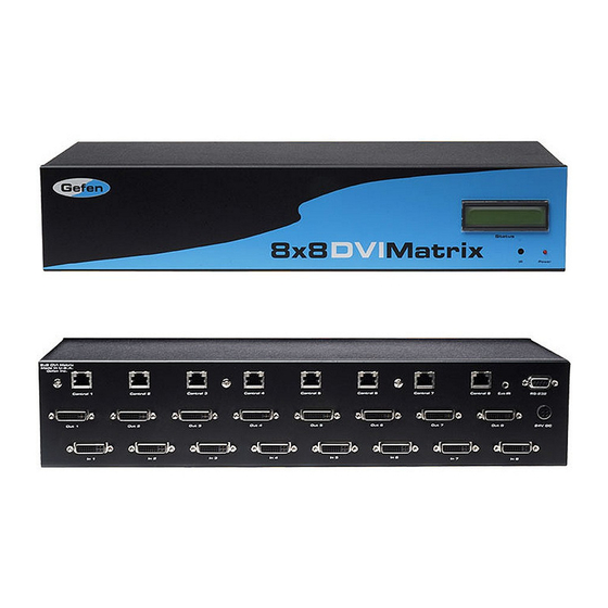
Page 7: 8X8 Dvi Matrix Front Panel Layout
8X8 DVI MATRIX FRONT PANEL LAYOUT... -
Page 8: 8X8 Dvi Matrix Front Panel Descriptions
8X8 DVI MATRIX FRONT PANEL DESCRIPTIONS LED Status Display This display will list the current display/source routes. Monitor (A~H) Selected Source (1~8) Monitor Output’s are labeled 1 through 8 on the rear panel of the 8x8 DVI Matrix. These numbers correspond to the letters A through H on the LED Status Display. -
Page 9: 8X8 Dvi Matrix Back Panel Layout
8X8 DVI MATRIX BACK PANEL LAYOUT... -
Page 10: 8X8 Dvi Matrix Back Panel Descriptions
8X8 DVI MATRIX BACK PANEL DESCRIPTIONS Optional Remote Switching Ports Ports 1 through 8 are used for remote switching using the optional component EXT-RMT-MATRIX-848. RS-232 Serial Control Interface This port is used for serial communication for multiple functions. Access to certain features are only through the RS-232 interface. -
Page 11: Ext-Rmt-Matrix-848 Panel Layout
EXT-RMT-MATRIX-848 PANEL LAYOUT Front Panel Back Panel (PRODUCT SOLD SEPARATELY) -
Page 12: Ext-Rmt-Matrix-848 Panel Descriptions
EXT-RMT-MATRIX-848 PANEL DESCRIPTIONS Direct Select Buttons When this unit is attached to a CAT-5 port that corresponds to a display on the 8x8 DVI Matrix, use buttons 1 through 8 to select what source that display will be viewing. Buttons 1 through 8 directly correspond to DVI source inputs 1 through 8 on the 8x8 DVI Matrix. -
Page 13: Connecting And Operating The 8X8 Dvi Matrix
CONNECTING AND OPERATING THE 8X8 DVI MATRIX How to Connect the 8x8 DVI Matrix Connect up to 8 DVI sources to the DVI Input ports on the 8x8 DVI Matrix using the supplied DVI cables. Connect up to 8 DVI displays to the DVI Output ports on the 8x8 DVI Matrix using user supplied DVI cables. -
Page 14: 8X8 Dvi Matrix Remote Description & Operation
8X8 DVI MATRIX REMOTE DESCRIPTION & OPERATION ATRIX REMOTE DESCRIPTION & O Buttons 1 through 8 on the RMT-16 IR remote control correspond to display outputs 8 on the RMT-16 IR remote control correspond A through H. Buttons 9 through 16 correspond to source inputs 1 through 8. Please ns 9 through 16 correspond to source inputs 1 t use the steps and chart below for instructions on how to route video sources to chart below for instructions on how to route vide... -
Page 15: Rmt-848Ir Ir Channel Confi Guration
RMT-848IR IR CHANNEL CONFIGURATION The RMT-848IR remote control has 4 discrete channels for use if the default IR code set confl icts with other remote control commands in your setup. There are 2 DIP Switches underneath the battery on the RMT-848IR remote control. These DIP Switches must match the IR channel in use on the 8x8 DVI Matrix. -
Page 16: Ext-Rmt-Matrix-848 Remote Operation
EXT-RMT-MATRIX-848 REMOTE OPERATION (PRODUCT SOLD SEPARATELY) Once the EXT-RMT-MATRIX-848 Remote is installed and connected to a remote output port on the 8x8 DVI Matrix, use the direct selection buttons to chose a source to view. Once a source is chosen, its corresponding LED should become active. -
Page 17: Rmt-8-Ir Ir Channel Confi Guration
RMT-8-IR IR CHANNEL CONFIGURATION The RMT-8-IR remote control (sold separately) has 4 discrete IR channels for use if the default IR code set confl icts with other remote control commands in your setup. There are 2 DIP Switches underneath the battery on the RMT-8-IR remote control that must match DIP Switches on the EXT-RMT-MATRIX-848. -
Page 18: Rs-232 Serial Control Interface
RS-232 SERIAL CONTROL INTERFACE 5 4 3 2 1 1 2 3 4 5 9 8 7 6 6 7 8 9 Only Pins 2 (RX), 3 (TX), and 5 (Ground) are used on the RS-232 serial interface RS232 Settings Bits per second .................... -
Page 19: Network Cable Wiring Diagram
Gefen has specifi cally engineered their products to work with the TIA/EIA-568-B specifi cation. Please adhere to the table below when fi eld terminating cable for use with Gefen products. Failure to do so may produce unexpected results and reduced performance. -
Page 20: Appendix A
APPENDIX A The 8X8 DVI Matrix has 4 banks of DIP Switches located on the underside of the main unit. This section will outline the function of each DIP Switch bank. DIP SWITCH BANKS Front Panel Bank A Bank B Bank C Bank D Rear Panel... - Page 21 APPENDIX A DIP SWITCH BANK B DIP Switch Monitor Description [OFF] 0 db pre-emphasis, [ON] 6 db pre-emphasis [OFF] 0 db pre-emphasis, [ON] 6 db pre-emphasis [OFF] 0 db pre-emphasis, [ON] 6 db pre-emphasis [OFF] 0 db pre-emphasis, [ON] 6 db pre-emphasis [OFF] 0 db pre-emphasis, [ON] 6 db pre-emphasis [OFF] 0 db pre-emphasis, [ON] 6 db pre-emphasis [OFF] 0 db pre-emphasis, [ON] 6 db pre-emphasis...
-
Page 22: Appendix B
MCU that the function name is ending. Finally, the parameters required for each function are separated by a space and ending by the ‘\r’ character or “Enter” Example: #FunctionName_param1_param2_param3_param4…\r RMT-848IR Address This function set the remote channel that must match the GEFEN RMT-848IR remote control. #RMT_param1\r Parameter... - Page 23 APPENDIX B DS EDID Store In Locals Edid This function reads EDID fi le from DS and store it in any input Locals EDID. #EDIDDSTOLO_param1_param2[_param3][_param4][_param5] [_param6] [_param7][_param8][_param9]\r Parameter Name Value MONITOR [A:H] 2 (3-9 optionally) INPUT [1:8] DS EDID Store In EDID Bank This function reads EDID fi...
- Page 24 APPENDIX B Route Input DDC To Local EDID This function routes the Input DDC to the Local EDID. #DDCTOLO_param1\r Parameter Name Value INPUT [1:8] Print DS EDID This function reads the DS EDID fi le and sends it to the serial port. #PRDSEDID_param1_param2\r Parameter Name...
- Page 25 APPENDIX B Print EDID Setting This function sends the EDID setting table to the serial port. #PRSEEDID\r Load EDID To Locals EDID These functions will load an EDID fi le through the serial port and store it in any Input’s Local EDID. #LOEDIDTOLO_param1_param2_param3[_param4][_param5][_param6] [_param7][_param8][_param9][_param10]\r Parameter...
- Page 26 APPENDIX B Set Default Setting This function will set the product back to its default setting. Routing state will be INPUT1-MONA, INPUT2-MONB, …, All the features with default to how the hardware switches are set. #DEF\r Set Preset Routing State This function enables the user to determine up to 10 routing states to save in memory.
Need help?
Do you have a question about the EXT-DVI-848 and is the answer not in the manual?
Questions and answers