Table of Contents
Advertisement
Quick Links
Advertisement
Table of Contents

Subscribe to Our Youtube Channel
Related Manuals for Gefen EXT-DVIKVM-LAN


Summary of Contents for Gefen EXT-DVIKVM-LAN
- Page 1 Over EXT-DVIKVM-LAN User Manual Release A1...
-
Page 2: Important Safety Instructions
DVI KVM over IP Important Safety Instructions GENERAL SAFETY INFORMATION Read these instructions. Keep these instructions. Heed all warnings. Follow all instructions. Do not use this product near water. Clean only with a dry cloth. Do not block any ventilation openings. Install in accordance with the manufacturer’s instructions. Do not install or place this product near any heat sources such as radiators, heat registers, stoves, or other apparatus (including amplifiers) that produce heat. Do not defeat the safety purpose of the polarized or grounding-type plug. A polarized plug has two blades with one wider than the other. A grounding type plug has two blades and a third grounding prong. The wide blade or the third prong are provided for your safety. If the provided plug does not fit into your outlet, consult an electrician for replacement of the obsolete outlet. 10. Protect the power cord from being walked on or pinched particularly at plugs, convenience receptacles, and the point where they exit from the apparatus. 11. Only use attachments/accessories specified by the manufacturer. 12. To reduce the risk of electric shock and/or damage to this product, never handle or touch this unit or power cord if your hands are wet or damp. Do not expose this product to rain or moisture. 13. Unplug this apparatus during lightning storms or when unused for long periods of time. 14. Refer all servicing to qualified service personnel. Servicing is required when the apparatus has been damaged in any way, such as power-supply cord or plug is damaged, liquid has been spilled or objects have fallen into the apparatus, the apparatus has been exposed to rain or moisture, does not operate normally, or has been dropped. -
Page 3: Warranty Information
This warranty is in lieu of all other warranties expressed or implied, including without limitation, any implied warranty or merchantability or fitness for any particular purpose, all of which are expressly disclaimed. Proof of sale may be required in order to claim warranty. Customers outside the US are responsible for shipping charges to and from Gefen. Copper cables are limited to a 30 day warranty and cables must be in their original condition. The information in this manual has been carefully checked and is believed to be accurate. However, Gefen assumes no responsibility for any inaccuracies that may be contained in this manual. In no event will Gefen be liable for direct, indirect, special, incidental, or consequential damages resulting from any defect or omission in this manual, even if advised of the possibility of such damages. The technical information contained herein regarding the features and specifications is subject to change without notice. For the latest warranty coverage information, refer to the Warranty and Return Policy under the Support section of the Gefen Web site at www.gefen.com. PRODUCT REGISTRATION Please register your product online by visiting the Register Product page under the Support section of the Gefen Web site. - Page 4 DVI KVM over IP Contacting Gefen Technical Support Gefen, LLC c/o Customer Service 20600 Nordhoff St. Chatsworth, CA 91311 Telephone: (818) 772-9100 (800) 545-6900 Fax: (818) 772-9120 Email: support@gefen.com Visit us on the Web: www.gefen.com Technical Support Hours: 8:00 AM to 5:00 PM Monday - Friday, Pacific Time DVI KVM over IP is a trademark of Gefen, LLC. Important Notice Gefen, LLC reserves the right to make changes in the hardware, packaging, and any accompanying documentation without prior written notice. © 2013 Gefen, LLC. All Rights Reserved. All trademarks are the property of their respective owners.
-
Page 5: Operating Notes
DVI KVM over IP Operating Notes • CAT-5 or CAT-6 cables should not exceed 330 feet (100 meters) between the Sender / Receiver unit and the network. • Shielded (STP) CAT-5 or CAT-6 is recommended. However, un-shielded (UTP) CAT-5 or CAT-6 is acceptable. • If If terminating network cables in the field, please adhere to the TIA/EIA568B specification. See the Network Cable Diagram for details. • The Gefen DVI KVM over IP features the ability to generate compat ble EDID and Hot Plug signals when working with different brands of source devices and monitors. • This product does not support HDCP. • Dual-link resolutions are not supported. IMPORTANT: The use of a Gigabit switch is required when connecting the DVI KVM over IP to a network. When using multicast mode, the Gigabit switch must have “jumbo frame” capability. The following table details the IP and IP port use of the DVI KVM over IP. Each “X” in the table, below, represents that no specified IP port is required. Type Sender A D Receiver Description (Host) (Client) 6751 A X msg_channel, ast_heartbeat UDP / MC X D 3246 ast_heartbeat multicast port Use the “multicast stream” multicast IP... - Page 6 DVI KVM over IP Operating Notes Type Sender A D Receiver Description (Host) (Client) control channel 1234 A X UDP / MC data streaming for both unicast and X D 1235 multicast mode Type Sender A D Receiver Description (Host) (Client) USB over IP data 6000 A X vhub_heartbeat 6755 A X USB over IP-specific Type Sender A D Receiver Description (Host) (Client) type 1 X D 6752 6752 A X type 2 Type Sender A D Receiver...
-
Page 7: Packing List
Supports resolutions up to 1080p Full HD and 1920 x 1200 (WUXGA) • Supports USB 2.0 data rates up to 480 Mbps in addition to backward-compatibility with USB 1.1 • EDID management for rapid integration of source and display devices • Supports up to sixteen (16) Senders and sixteen (16) Receivers on network • Field-upgradable firmware • Locking power supply connectors • 1U tall, half-rack width enclosures are rack-mountable using EXT-RACK-1U bracket • Wall or under-shelf mount brackets included 1080P Packing List The DVI KVM over IP ships with the items listed below. If any of these items are not present in the box when you first open it, immediately contact your dealer or Gefen. • 1 x DVI KVM over IP (Sender unit) • 1 x DVI KVM over IP (Receiver unit) • 1 x 6 ft. DVI cable (M-M) • 1 x 6 ft. USB cable (A-B) • 1 x 6 ft. DB-9 cable (M-F) • 1 x Mounting rack with screws • 2 x 5V DC power supplies • 1 x Quick-Start Guide... -
Page 8: Table Of Contents
DVI KVM over IP Table of Contents Getting Started Sender Panel Layout ..................... 2 Front ......................2 Back ......................3 Bottom ......................4 Receiver Panel Layout ..................5 Front ......................5 Back ......................6 Installation ......................7 Connecting to a Local Area Network (LAN) ..........7 Direct Connection ..................7 Supplementary Connections ................. 8 Sample Wiring Diagram ................ -
Page 11: 01 Getting Started
Over 01 Getting Started Sender Panel Layout ..................... 2 Front ......................2 Back ......................3 Bottom ......................4 Receiver Panel Layout ..................5 Front ......................5 Back ......................6 Installation ......................7 Connecting to a Local Area Network (LAN) ..........7 Direct Connection ..................7 Supplementary Connections ................. 8 Sample Wiring Diagram ................9... -
Page 12: Sender Panel Layout
Getting Started Sender Panel Layout Front Name Description Power This LED glows bright blue when the unit is connected to an AC outlet and the unit is powered ON. Link This LED glows bright green when the Sender unit and Receiver unit are connected using Ethernet cable. Mode Press this button to switch between Graphic Mode and Video Mode. Graphic Mode optimizes still images. Video Mode is best used for optimizing video. See Video Modes for details. Reset Press this button to reset the unit. page | 2... -
Page 13: Back
Getting Started Sender Panel Layout Back Name Description DVI In Connect the included DVI cable from this connector to the DVI source. RS-232 Connect the included RS-232 cable from this port to an RS-232 device. See Using RS-232 for details. Line In Connect a 3.5mm mini-stereo cable from the Line Out jack on the multimedia PC to this jack. Line Out Connect a 3.5mm mini-stereo cable from this jack to the Line In jack of a multimedia PC. Connect a USB cable from the computer to this USB port. Link Connects the Sender unit to the network (or directly to the Receiver unit) using an Ethernet cable. IR Out Connect an IR Blaster cable (Gefen part no. EXT-2IREMIT) from this jack to the Hi-Def source to control the source from the viewing location. 5V DC Connect the included 5V DC locking power supply to this power receptacle. page | 3... -
Page 14: Bottom
Getting Started Sender Panel Layout Bottom Name Description Rotary switch Used to set the video channel for the Sender unit. Each Sender unit can be set to a different channel. See Setting the Video Channel for details. page | 4... -
Page 15: Receiver Panel Layout
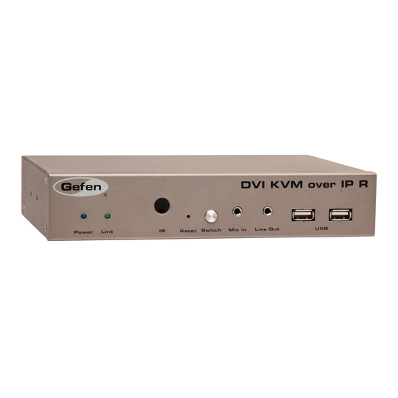
Getting Started Receiver Panel Layout Front Name Description Power This LED glows bright blue when the unit is connected to an AC outlet and the unit is powered ON. Link This LED glows bright green when the Sender unit and Receiver unit are connected using CAT-5 / CAT-6 cable. This IR sensor receives signals from the source IR remote control. Reset Press this button to reset the unit. Switch Switches the communication channel when using multiple Receiver units on a network. See Setting the Video Channel for details. Mic In Connect a microphone to this jack. If the microphone has a 1/4” jack, use a 1/4”-to- 3.5mm adapter to connect the microphone to the Receiver unit. Line Out Connect a 3.5mm mini-stereo cable to a pair of powered speakers. Connect up two USB devices to these USB ports. page | 5... -
Page 16: Back
Getting Started Receiver Panel Layout Back Name Description DVI Out Connect a DVI cable from this connector to the DVI display. RS-232 Connect the included RS-232 cable from this port to an RS-232 device. See Using RS-232 for details. Ethernet Connects the Receiver unit to the network (or directly to the Sender unit) using an Ethernet cable. See the next page for installation instructions. IR Ext Connect an IR Extender cable (Gefen part nos. EXT-RMT-EXTIRC or EXT-RMT-EXTIRN) from this port to extend the IR control distance. 5V DC Connect the included 5V DC locking power supply to this power receptacle. page | 6... -
Page 17: Installation
Getting Started Installation The DVI KVM over IP Sender and Receiver units can either be connected over a Local Area Network or they can be directly connected to one another. Connecting to a Local Area Network (LAN) Connect a CAT-5e (or better) cable between the Link jack on the Sender unit and your LAN connection, via a switch or router. Connect any one of the three Ethernet ports on the Receiver unit to the LAN. Although any of the Ethernet ports can be used, it is recommended to use Ethernet port 1 for connecting the Receiver unit to the LAN, in order to easily identify this as the “LAN cable”. Connect any additional IP-based devices or daisy-chain additional Receiver units to Ethernet ports 2 and 3. Connect to router or switch Sender unit Connect to other Connect to LAN Receivers / IP devices Receiver unit Direct Connection Connect a CAT-5e (or better) cable from the Link jack on the Sender unit to the Ethernet 1 jack on the Receiver unit. Although you can connect the CAT-5e cable to any of the three Ethernet ports, it is recommended that Ethernet 1 is used for the first connection. This leaves Ethernet port 2 and 3 open for connecting additional devices or when daisy-chaining Receiver units. (continued on next page) page | 7... -
Page 18: Supplementary Connections
Connect to additional Connect to Sender unit Receivers Receiver unit NOTE: When directly connecting the Sender and Receiver unit, the DVI KVM over IP must be set to Auto IP mode. See Configuring Auto IP Mode for instructions on setting Auto IP mode. Supplementary Connections ► Video Use the included DVI cable to connect the DVI source to the DVI In port on the Sender unit. Connect a DVI cable from the DVI display to the DVI Out port on the Receiver unit. ► USB (see USB Control for more information on using USB devices) Connect a USB cable from the computer to the USB port on the Sender unit. Connect up to two USB devices to the Receiver unit. ► Connect a Gefen IR Emitter (Gefen part no. EXT-2IREMIT) to the Sender unit and attach it to the IR sensor on the device to be controlled. Connect an IR Extender (Gefen part no. EXT-RMT-EXTIRC or EXT-RMT-EXTIRN) to the Receiver unit if the IR sensor will not be within line-of-site for proper IR control. page | 8... -
Page 19: Sample Wiring Diagram
DVI CABLE USB CABLE Gigabit Switch AUDIO CABLE MIC CABLE RS-232 CABLE IR EMITTER Receiver IR EXTENDER Multimedia PC IR Emitter Microphone RS-232 Controlled USB Mouse Device USB Keyboard IR Extender Sender Powered Speakers or headphones HD Display EXT-DVIKVM-LAN page | 9... -
Page 21: Operating The Dvi Kvm Over Ip
Over 02 Operating the DVI KVM over IP The Linking Process .................... 12 Network Configuration ..................13 Accessing the Web Interface ..............13 Configuring Auto IP Mode ................15 Changing Network Settings on the Computer ..........18 Configuring Static IP Mode ................. 22 Configuring DHCP Mode ................22 Setting the Video Channel ................... 23 Unicast and Multicast Modes ................26 Configuring Unicast Mode ................26 Switching between displays in Unicast mode .......... -
Page 22: The Linking Process
Operating the DVI KVM over IP The Linking Process By default, the DVI KVM over IP is shipped in DHCP mode. DHCP mode should work in most cases, since the Sender and Receiver units are assigned an IP address by the DHCP server or router. After all the connections have been made, the DVI KVM over IP will attempt to establish a connection between the Sender and Receiver unit. NOTE: When directly connecting the Sender and Receiver units, both the Sender and Receiver unit must be set to Auto IP mode. See Configuring Auto IP Mode for information. During this time,, the Link LED on both the Sender and Receiver unit will begin to flash and the message “Trying to find the gateway” will be displayed on the screen. FW: 12-Dec-24 b6e4 Local IP: 192.168.1.8 Remote IP: 192.168.1.9 Trying to find the gateway... ID: 82B9969C6B9E Once a successful connection is established, the Link LED on the Sender and Receiver unit(s) will glow bright green and the source signal will appear on the display. -
Page 23: Network Configuration
Operating the DVI KVM over IP Network Configuration If DHCP mode is not desired, the DVI KVM over IP can also be set to Auto IP mode or Static IP mode. In order to change the network options, both the Sender and Receiver unit contain a built-in Web interface. Changing the network settings may also be necessary when using multiple Sender and Receiver units. Accessing the Web Interface Connect an Ethernet cable from a computer to the network on which the DVI KVM over IP is connected. Identify the IP address of both the Sender and Receiver unit. This can be done by viewing the display, during the linking process. If the Sender and Receiver units are already displaying a picture and the IP addresses are not known, switch the video channel on the Receiver unit to display the IP information. See Setting the Video Channel for information on how to switch the video channel. Receiver (client) unit IP address FW: 12-Dec-24 b6e4 Local IP: 192.168.1.8 Remote IP: 192.168.1.9 Trying to find the gateway... - Page 24 Operating the DVI KVM over IP Network Configuration The following page will be displayed: “h” identifies this page as the Sender (host) unit. Open another tab or window in the Web browser and enter the IP address of the Receiver (client) unit. The page for the Receiver unit will appear very similar to that of the Sender unit. In addition to the IP address, the Web page of the Sender unit is identified with an “h” (for “host”), under the Version Information section, as shown above. The Web page for the Receiver unit will be identified with a “c”, for “client” page | 14...
-
Page 25: Configuring Auto Ip Mode
Operating the DVI KVM over IP Network Configuration Configuring Auto IP Mode Auto IP mode is used when there is no DHCP server (or router) available and each Sender and Receiver unit is connected to a switch. When set to Auto IP mode, the Sender and Receiver unit will self-assign unique IP addresses (within the range of 169.254.x.x). Use this mode when the Sender and Receiver unit are directly connected. Access the Web interface of the Sender (host) unit by entering the IP address of the Sender unit in a Web browser. Once the Web page is displayed, click the Utilities bar to expand it. Click the Console API Commmand text box. page | 15... - Page 26 Operating the DVI KVM over IP Network Configuration Type the following command in the Console API Command text box: astparam s ip_mode autoip; astparam save; reboot Click the Apply button. The “Loading” message will appear, indicating that the commands are being executed. “Loading” message indicates commands are being executed After a few moments, the following message will appear at the top of the Web page: page | 16...
- Page 27 Operating the DVI KVM over IP Network Configuration Although this message will be presented when there is an error in the command line, it is important to understand that this also occurs after the network mode has been changed. This is because the IP address has changed and the Web page can no longer access the current IP address of the Sender (or Receiver) unit. Once the process has completed, the new IP address will appear on the display, as shown below: FW: 12-Dec-24 b6e4 Local IP: 192.168.1.8 Remote IP: 169.254.7.8 Trying to find the gateway... ID: 82B9969C6B9E New IP address The new IP address of the Sender unit is no longer in the same subnet as the Receiver unit. Therefore, the Sender unit will not be able to communicate with the Receiver unit until the Receiver unit is also set to Auto IP mode. Repeat steps 1 through 7 for the Receiver unit. 10. Once both units are configured for Auto IP mode, video communication will be restored.
-
Page 28: Changing Network Settings On The Computer
Operating the DVI KVM over IP Network Configuration Changing Network Settings on the Computer We just finished configuring the Sender and Receiver units to Auto IP mode. In order to configure these units for Static IP mode (or to return to DHCP mode), we will need to configure each unit separately. However, because we are no longer using DHCP to assign IP addresses, we will need to modify our network settings to match those of the Sender and Receiver units. Let’s continue from our previous example. First, we will identify the current IP settings for our Sender and Receiver unit. Once again, if the Sender and Receiver units are already displaying a picture, switch the channel on the Receiver unit to display the IP information. See Setting the Video Channel for information on how to switch the video channel on the Receiver unit. FW: 12-Dec-24 b6e4 Local IP: 169.254.7.11 Remote IP: 169.254.7.8 Trying to find the gateway... ID: 82B9969C6B9E As we can see in the illustration, above, the IP addresses for the Sender and Receiver unit are 169.254.7.8 and 169.254.7.11, respectively. Therefore, we must change our computer’s IP address so that it falls within the same subnet... - Page 29 Operating the DVI KVM over IP Network Configuration Double-click on the Local Area Connection icon to display the Local Area Connection Status dialog. Click the Properties button. Click on Internet Protocol Version 4 (TCP/IPv4). page | 19...
- Page 30 Operating the DVI KVM over IP Network Configuration Click the Properties button to display the Internet Protocol Version 4 (TCP/IPv4) Properties dialog. STOP: If the computer that is connected does not use Obtain an IP address automatically and Obtain DNS server address automatically, write down the current IP settings before making changes, in order to restore them later. Change the IP address field to an IP address that is within the range of the Sender unit. We will use an IP address of 169.254.7.1, since it is unused. Click the Use the following IP Clear these boxes address radio button Click the Use the following DNS server address radio button page | 20...
- Page 31 Operating the DVI KVM over IP Network Configuration Click the OK button, then close all Control Panel windows. 10. Launch a Web browser and type in the IP address for the Sender unit. In our example, the IP address for the Sender unit is 169.254.7.8 11. The Sender unit page will now be displayed. Because we have already configured the IP address for the computer that will be accessing the Web page for the Sender unit, we can also access the Receiver unit. 12. To access the Receiver unit, disconnect the network cable from the Receiver unit and connect the computer directly to the Receiver unit. Once the computer is connected, enter the IP address of the Receiver unit to access the Web interface on the Receiver unit. As long as the Sender and Receiver units are within the same address range, this procedure only needs to be performed once. 13. We can now proceed to change the network configuration to Static IP mode or DHCP mode. See the next page for details on configuring Static IP Mode and DHCP mode. page | 21...
-
Page 32: Configuring Static Ip Mode
Operating the DVI KVM over IP Network Configuration Configuring Static IP Mode Access the Web interface of the Sender (host) unit by entering the IP address of the Sender (or Receiver) unit in a Web browser. See Accessing the Web Interface. Once the Web page is displayed, click the Utilities bar to expand it. Click the Console API Commmand text box and type the following command line (all on one line). Make sure to replace the IP address (192.168.1.100) and the net mask (255.255.255.0) with the desired values. astparam s ip_mode static; astparam s ipaddr 192.168.1.100; astparam s netmask 255.255.255.0; astparam save; reboot Click the Apply button. Configuring DHCP Mode As stated earlier, the DVI KVM over IP ships in DHCP mode. In order to return to DHCP mode, use the following procedure: Access the Web interface of the Sender (host) unit by entering the IP address of the Sender (or Receiver) unit in a Web browser. See Accessing the Web Interface. -
Page 33: Setting The Video Channel
Operating the DVI KVM over IP Setting the Video Channel In order for the Receiver unit to acquire the desired source (connected to the Sender unit), the Sender and Receiver unit(s) must be set to the same channel. It’s very similar to changing the channel on a cable box or television. This applies when using both multiple and single Sender units. By default, the Sender and Receiver units are set to channel 0 (zero). We will use the illustration below as an example and assign channel 02 to both a Sender and Receiver unit. Receiver unit Channel:02 DVI Out Sender unit Channel:03 Receiver unit No signal Channel:06 Sender unit Channel:02 DVI In Sender unit Channel:05 DVI In DVI In On the bottom of each Sender unit (see page 4), is a 16-position rotary switch. - Page 34 Operating the DVI KVM over IP Setting the Video Channel Reboot the Sender unit for the channel-change to take effect. Rebooting the Sender unit (or the Receiver unit) can be performed in one of three ways: 1) Disconnect and reconnect the power supply. 2) Click the Reboot button on the Web interface. 3) Type reboot in the Console API Command text box and click the Apply button. Press the Switch button on the front panel of the Receiver unit. Switch button The current channel will be displayed. In this example, we will assume that the Receiver channel is currently set to channel 0. Because the Receiver unit is not set to the same channel as the Sender unit, the source signal is not displayed. Channel:00 FW: 12-Dec-24 b6e4 Local IP: 192.168.1.8 Remote IP: 192.168.1.7 Trying to find the gateway... ID: 82B9969C6B9E page | 24...
- Page 35 Operating the DVI KVM over IP Setting the Video Channel Once the current channel is displayed, consecutively press the Switch button on the front panel of the Receiver unit until “Channel 02” is displayed. If the channel is not changed within a specific amount of time, the current channel setting will disappear from the screen. If this is the case, press the Switch button once to display the current channel. TIP: The current channel of the Receiver unit can always be displayed, without changing the channel, by pressing the Switch button once. After a few moments, the source signal will appear on the display. Channel:02 We can see from our example that since both the Sender and Receiver unit have been set to channel 02, the source is being displayed. However, the other Receiver unit, in the illustration on page 23, is set to Channel 06. This Receiver unit will not receive any video data unless one of the remaining two Sender units is set to channel 06. NOTE: The DVI KVM over IP can be used with up to 16 Sender units to provide switching capability between each Receiver unit. Up to 256 Receiver units are supported. Each Receiver unit can be set to receive video data from any one of 16 Sender units. page | 25...
-
Page 36: Unicast And Multicast Modes
Operating the DVI KVM over IP Unicast and Multicast Modes The DVI KVM over IP has two operating modes: Unicast and multicast. In unicast mode, only a single Receiver unit can display video using multiple (or a single) Sender unit on the same network. In Multicast mode, multiple Receiver units can receive signals from multiple (or a single) Sender unit on the same network. By default, the DVI KVM over IP is shipped in unicast mode. Configuring Unicast Mode NOTE: As mentioned earlier, the DVI KVM over IP is shipped in unicast mode. If the units are configured in multicast mode, the following procedure will not need to be performed after unpacking and connecting the product. To illustrate an example of how unicast mode works, we will use the following diagram. We have arbitrarily set up three Sender units and two Receiver units. For reference, we will identify the Sender units as 1 through 3 and the Receiver units A and B. Receiver unit DVI Out Sender unit DVI Out Receiver unit Sender unit... - Page 37 Operating the DVI KVM over IP Unicast and Multicast Modes Click the Network tab and click the Unicast button. When selected, the Unicast button will be highlighted in green. Click the Apply button. page | 27...
- Page 38 Operating the DVI KVM over IP Unicast and Multicast Modes A message will be displayed, indicating that the casting mode has been applied to the Receiver unit. After a few moments, another message will be displayed stating that the Receiver unit must be rebooted in order for the new settings to take effect. page | 28...
- Page 39 Operating the DVI KVM over IP Unicast and Multicast Modes Reboot the Receiver unit by one of these methods: 1) Disconnect and reconnect the power supply. 2) Click the Reboot button on the Web interface. 3) Type reboot in the Console API Command text box and click the Apply button. Repeat steps 1 through 6 for each Sender and Receiver on the network. Now that each device has been configured, we need to specify which channels will be used by each Sender and Receiver unit. It is important to note that when using unicast mode, that only one Receiver can display video at a time from the selected channel. Let’s illustrate this using our original diagram. We’ve added some numbers in red to denote which channels are being used by each Sender and Receiver. The channel numbers are arbitrary. Receiver unit Sender unit Receiver unit Sender unit DVI In Sender unit DVI In DVI In In this example above, Receiver unit B is set to channel 02 and Receiver A is set to channel 03. Sender unit 3 is also set to channel 02. As expected, the source signal (indicated by the red line) from Sender unit 3 appears on the display connected to Receiver unit B.
-
Page 40: Switching Between Displays In Unicast Mode
Operating the DVI KVM over IP Unicast and Multicast Modes Switching between displays in Unicast mode In order to control which display receives the source signal, press the Switch button on the Receiver unit to change the channel. For example, let’s say we want to send the DVI source to Receiver unit A. Receiver unit Sender unit Receiver unit Sender unit DVI In Sender unit DVI In DVI In Press the Switch button on Receiver unit A and set the channel to 02. At this point, both Receiver unit A and Receiver unit B are set to channel 02. However, because the DVI KVM over IP is in unicast mode, only one Receiver can display the source signal (from a Sender unit) at a time. Since Receiver unit B was set to channel 02, first, Receiver unit B has priority and will continue to receive the source signal until its channel is changed. - Page 41 Operating the DVI KVM over IP Unicast and Multicast Modes Channel:02 FW: 12-Dec-24 b6e4 Local IP: 192.168.1.8 Remote IP: 192.168.1.7 Trying to find the gateway... ID: 82B9969C6B9E To release Receiver unit B from receiving the DVI source signal, press the Switch button and change the channel on Receiver unit B to something other than channel 02. For this example, we’ll set Receiver unit B to channel 03. Receiver unit A will now display the DVI source signal. When using unicast mode, the DVI KVM over IP behaves as a DVI KVM Switcher. Receiver unit Sender unit Receiver unit Sender unit DVI In Sender unit...
-
Page 42: Configuring Multicast Mode
Operating the DVI KVM over IP Unicast and Multicast Modes Configuring Multicast Mode NOTE: When using multicast mode, use a Gigabit switch with “Jumbo Frame” capability (enabled) to ensure the best video quality. To illustrate an example of how multicast mode works, we will use the same diagram that was used in Configuring Unicast Mode. Once again, we have arbitrarily set up three Sender units and two Receiver units. For reference, we will identify the Sender units as 1 through 3 and the Receiver units A and B. Receiver unit Sender unit Receiver unit Sender unit DVI In Sender unit DVI In DVI In Access the Web interface for each Sender and Receiver unit that will be using multicast mode. In this example, we will start by configuring Receiver unit A. Click the Network tab and click the Multicast button. When selected, the Multicast button will be highlighted in green (see Configuring Unicast Mode for a reference to the Web interface). -
Page 43: Using Rs-232
Operating the DVI KVM over IP Unicast and Multicast Modes Using RS-232 The DVI KVM over IP supports RS-232 pass-through, allowing the control of remote RS-232 devices (near the Receiver unit) from the source (Sender unit) location. The RS-232 host (controller) and device (client) must be set to the same baud rate. In addition, the correct baud rate must be set on the Sender and Receiver units which are being used to control the RS-232 client. In the example below, the Gefen 4x1 HD Switch w/ Audio Decoding (Gefen part no. GTV-AUDDEC-N) has been connected to Receiver unit A. This is the RS-232 client. We want to control this product from Sender unit 3, using a laptop PC (RS-232 host). We have arbitrarily assigned channel 12 to both the Sender and associated Receiver unit. Receiver unit DVI Out Sender unit DVI Out Receiver un t RS-232 controller (Computer) Sender un t... - Page 44 Operating the DVI KVM over IP Unicast and Multicast Modes NOTE: If the Enable Serial over IP is not checked, then RS-232 pass-through will be disabled. Select the baud rate of the RS-232 controller by selecting it from the drop-down list in the Baudrate field. Repeat this process for the Data bits, Parity, and Stop bits. The DVI KVM over IP does not support flow control. Click the Apply button in the lower right-hand corner of the screen. page | 34...
- Page 45 Operating the DVI KVM over IP Unicast and Multicast Modes A message will be displayed, indicating that the new Serial over IP settings have been applied to the Sender unit. After a few moments, another message will be displayed stating that the Sender unit must be rebooted in order for the new settings to take effect. page | 35...
- Page 46 DVI Out Sender unit DVI Out Receiver un t RS-232 controller (Computer) Sender un t DVI In Sender unit D E C A U D RS-232 device DVI In (GTV-AUDDEC-N) DVI In ► Multicast Mode When using multicast mode, multiple Receiver units will be able to communicate with the RS-232 host (Computer) device. For instance, if we expand on our original example by connecting a Gefen 4x1 HD Switcher to Receiver A, B, and C (not shown), then we could control all three devices simultaneously. page | 36...
-
Page 47: Usb Control
Operating the DVI KVM over IP Unicast and Multicast Modes USB Control When connecting USB devices to the DVI KVM over IP, the functionality is similar to that of video and RS-232. As an example, we will connect a computer to the Sender unit 2 and a mouse device to Receiver unit B. Since we are connecting a USB (mouse) device to only one of the Receiver units, it does not matter whether we are in unicast or multicast mode. Connect the USB host device to the Sender unit. Connect up to two USB devices to the Receiver unit(s). The mouse device can now be used to control the computer that is connected to Sender unit 2. Receiver unit DVI Out Sender unit DVI Out Receiver unit Sender unit DVI In Sender unit DVI In DVI In page | 37... -
Page 48: Audio Input And Output
Operating the DVI KVM over IP Unicast and Multicast Modes ► Unicast Mode In unicast mode, only a single Receiver unit will be able to communicate with a Sender unit. However, multiple USB devices can be connected to multiple Receiver units. Use the Switch button to change channels to the desired Receiver unit. ► Multicast Mode In multicast mode, the USB host device can be controlled from multiple Receiver units at one time. When using multicast mode, the Switch button must be pressed on each Receiver unit in order to enable USB on each Receiver unit. In multicast mode, the DVI KVM over IP behaves like a USB hub. Connecting multiple mouse / keyboard devices to each Receiver unit makes little sense if multiple users are attempting to control the same computer. However, if different USB devices are connected, each remote station (Receiver unit) can use a USB device without interference. Audio Input and Output To illustrate how audio works with the DVI KVM over IP, we will set up a microphone and some speakers. Since we already have a mouse device connected to our computer, we will continue using the setup illustrated on the previous page. The Sender and Receiver unit are set to unicast mode. Our computer has a Mic In jack, as part of the sound card. However, we want to be able to access this jack from the Receiver unit. Therefore, connect the microphone to the Mic In jack on the Receiver unit. - Page 49 Operating the DVI KVM over IP Unicast and Multicast Modes WARNING: DO NOT connect the cable from the Line Out jack on the Sender unit to the Mic In jack on the computer. Doing so will result in audio “clipping” and may cause damage to the sound card. Connect to Line Out on computer Sender unit Connect to Line In on computer NOTE: When using HDMI sources with an HDMI-to-DVI adapter, the HDMI audio will be passed through to the DVI Out connector. However, if a 3.5mm-to-3.5mm mini-stereo cable is connected to the Line In jack on the Sender unit, the embedded HDMI audio is switched off. This allows the audio signal from the Line In jack (Sender unit) to be received on the Line Out jack (Receiver unit). Now let’s connect another 3.5mm-to-3.5mm mini-stereo cable between the Line Out jack on the computer and the Line In jack on the Sender unit. Finally, we’ll connect our computer speakers to the Line Out jack on the Receiver unit. Connect to computer speakers page | 39...
- Page 50 Operating the DVI KVM over IP Unicast and Multicast Modes Let’s take a look at our setup. All new audio connections that were made are highlighted in blue. Note that in the diagram, below, we have indicated (using the dashed line) that either the computer or an MP3 player (e.g. iPod, etc.) can be connected to the Line In jack on the Sender unit. Of course, if another device is connected to the Line In jack on the Sender unit (instead of the computer), then the audio signal coming from the microphone will not be heard. Microphone VGA Out Powered speakers Sender unit VGA Out Receiver unit Receiver unit Sender unit VGA In Sender unit VGA In VGA In MP3 player When using a microphone, the audio behavior will differ between unicast and multicast...
-
Page 51: Disabling / Enabling Video
Operating the DVI KVM over IP Unicast and Multicast Modes Disabling / Enabling Video This can be useful when ‘masking’ video which prevents it from being displayed. This feature is available under the Functions tab on both the Sender (host) and Receiver (client) Web interface, as shown below. Uncheck this box to disable video ► Unicast Mode In unicast mode, either the desired Receiver unit or the Sender unit can be disabled. ► Multicast Mode In multicast mode, the behavior is the same as unicast mode. page | 41... -
Page 52: Video Modes
Operating the DVI KVM over IP Video Modes The DVI KVM over IP provides two video modes: Video Mode and Graphic Mode. Consecutively pressing the Mode button on the Sender unit will toggle between Video Mode and Graphic Mode. • If the DVI signal is a video source, press the Mode button on the front panel of the Sender unit until “Video Mode” is displayed in the foreground of the video image. Set the DVI KVM over IP to Video Mode to optimize the frame rate. Video Mode • If the DVI signal is a graphic source (e.g. images, pattern generator, etc.), press the Mode button on the front panel of the Sender unit until “Graphic Mode” is displayed in the foreground of the graphic image. Set the DVI KVM over IP to Graphic Mode to maintain the sharpest image poss ble Graphic Mode page | 42... -
Page 53: Edid Management
Operating the DVI KVM over IP EDID Management The DVI KVM over IP features EDID Management. Before the source can send video (and/or audio) data, the source device (connected to each Sender unit) reads the EDID (Extended Display Identification Data) from the displays which are connected to each Receiver unit. The EDID contains information about what type of audio/video data can be accepted from the source. By default, the internal DVI EDID (stored in the Sender unit) is used. However, a downstream EDID (from a display, etc) can be retrieved and stored in the Sender unit. Storing a Downstream EDID For this example, we will use our original set up. We are currently using the default DVI EDID but now we want Display A to use the same EDID as Display B. Display B Display A Receiver unit Sender unit Receiver unit Sender unit DVI In Sender unit DVI In DVI In Access the Web interface for the Sender unit. - Page 54 Operating the DVI KVM over IP EDID Management Sender unit Make sure this box is not checked NOTE: Selecting or deselecting any check box within the Web interface will not automatically enable or disable the feature. Always click the Apply button then reboot the unit to save the changes Access the Web interface for the Receiver unit that is connected to Display B. Click the Copy EDID from this Video Output check box. Check this box Receiver unit page | 44...
- Page 55 Operating the DVI KVM over IP EDID Management Click the Apply button within the Video over IP section. Reboot the Receiver unit by one of these methods: 1) Disconnect and reconnect the power supply. 2) Click the Reboot button on the Web interface. 3) Type reboot in the Console API Command text box and click the Apply button. The EDID from Display B will now be used by the Sender unit (Sender 3). If any other Receiver units with displays are connected to the network, these displays will also use the EDID from Display B. Display B Display A (using EDID of Display B) Receiver unit Sender unit Receiver unit Sender unit DVI In Sender unit DVI In DVI In page | 45...
-
Page 56: Restoring The Default Dvi Edid
Operating the DVI KVM over IP EDID Management Restoring the Default DVI EDID Beginning with our last example (see diagram on previous page), we will restore the default DVI EDID used by the Sender unit (used when the unit is shipped). Access the Web interface for Receiver unit B which was used to transmit the EDID to the Sender unit. Uncheck this box Uncheck the Copy EDID from this Video Output check box, then click the Apply button within the Video over IP section. Reboot the Receiver unit. BEFORE CONTINUING: If other Receiver units are connected, repeat steps 1 -3. Access the Web interface for the Sender unit that is being used by the DVI source. Check this box Check the Reset EDID to Default Value check box. page | 46... - Page 57 Operating the DVI KVM over IP EDID Management Click the Apply button within the Video over IP section. Reboot the Sender unit. The default EDID (within the Sender unit) will now be used by read by each display. When each display reads the EDID of the DVI source, it will read the default DVI EDID stored in the Sender unit. Display B Display A Receiver unit Sender unit Receiver unit Sender unit DVI In Sender unit DVI In DVI In page | 47...
-
Page 59: 03 Appendix
Over 03 Appendix Network Cable Diagram ..................50 Rack Tray Installation ..................51 Specifications ...................... 52... -
Page 60: Network Cable Diagram
Appendix Network Cable Diagram Front of RJ-45 Connector 1 2 3 4 5 6 7 8 Gefen recommends the TIA/EIA-568-B wiring option. Use the table below when field-terminating cable for use with Gefen products. Color Description Orange / White TD+ (Transmit Data, positive differential signal) Orange TD- (Transmit Data, negative differential signal) Green / White RD+ (Receive Data, positive differential signal) Blue Unused Blue / White Unused Green RD- (Receive Data, negative differential signal) Brown / White Unused Brown / White Unused CAT-5, CAT-5e, and CAT-6 cabling comes in stranded and solid core types. Gefen recommends using solid core cabling. CAT-6 cable is also recommended. It is recommended to use one continuous run from one end to the other. Patch cable is not recommended. page | 50... -
Page 61: Rack Tray Installation
Appendix Rack Tray Installation The following illustrations provide instructions for installing the Sender and/or Receiver unit(s) in the Gefen 1U Rack Tray (Gefen part no. EXT-RACK-1U). Step 1 Step 2 Turn unit upside down. Remove rubber feet. Step 3 Step 4 Line up holes on unit and rack tray. Install countersink screws . Step 5 Step 6 Ensure the unit is installed securely. -
Page 62: Specifications
Appendix Specifications Supported Formats Resolutions (max.) • 1080p Full HD • 1920 x 1200 (WUXGA) Electrical Maximum Pixel Clock • 165 MHz Link indicator (Sender / Receiver) • 1 x LED, green Power indicator (Sender / Receiver) • 1 x LED, blue Connectors Video Input (Sender) • 1 x DVI-I 29-pin, female Video Output (Receiver) • 1 x DVI-I 29-pin, female Audio (Sender) • 1 x 3.5mm mini-stereo (Line In) • 1 x 3.5mm mini-stereo (Mic Out) Audio (Receiver) • 1 x 3.5mm mini-stereo (Line Out) • 1 x 3.5mm mini-stereo (Mic In) USB (Sender) • 1 x Type B, female USB (Receiver) • 2 x Type A, female Ethernet (Sender) •... - Page 63 Appendix Specifications Operational Power Input (Sender / Receiver) • 1 x 5V DC, locking Power Consumption (Sender / Receiver) • 10W (max.) Physical Dimensions (W x H x D) • 8.4” x 1.7” x 4.5” (Sender / Receiver) (213mm x 43mm x 113mm) Unit Weight (each unit) • 2 bs (0.9 kg) page | 53...
- Page 64 Stretch it, Switch it, Split it, Control it. Gefen’s got it. ® 20600 Nordhoff St., Chatsworth CA 91311 1-800-545-6900 818-772-9100 fax: 818-772-9120 www.gefen.com support@gefen.com This product uses UL or CE listed power supplies.
Need help?
Do you have a question about the EXT-DVIKVM-LAN and is the answer not in the manual?
Questions and answers