Table of Contents
Advertisement
Quick Links
Download this manual
See also:
User Manual
Advertisement
Table of Contents

Subscribe to Our Youtube Channel
Related Manuals for Gefen EXT-DVIKVM-841DL


Summary of Contents for Gefen EXT-DVIKVM-841DL
- Page 1 ® 8x1 DVI KVM DL/SL Switcher EXT-DVIKVM-841DL User Manual www.gefen.com...
- Page 2 Notice Gefen Inc. reserves the right to make changes in the hard ware, packaging and any accompanying doc u men ta tion without prior written notice. 8x1 DVI KVM DL/SL Switcher is a trademark of Gefen Inc. © 2010 Gefen Inc., All Rights Reserved...
-
Page 3: Table Of Contents
CONTENTS Introduction Operation Notes Features Panel Layout Panel Descriptions Connecting & Operating The 8x1 DVI KVM DL/SL Switcher 8x1 DVI KVM DL/SL Remote Description 8x1 DVI KVM DL/SL Switcher Remote Installation RMT-8IR Remote and 8x1 KVM Switcher Confi guration 10 EDID Modes 12 DL (Dual Link) Only Modes 13 RS-232 Serial Communication 14 RS-232 Serial Communication Commands... -
Page 4: Introduction
The Gefen 8x1 DVI KVM DL/SL Switcher The rack-mountable Gefen 8x1 dual link/single link DVI KVM Switcher offers an economical solution by eliminating the need to purchase many displays for each computer in a studio or lab situation. -
Page 5: Operation Notes
OPERATION NOTES READ THESE NOTES BEFORE INSTALLING OR OPERATING THE GEFEN 8X1 DVI KVM DL/SL SWITCHER • The 8x1 DVI KVM DL/SL Switcher will take any of up to eight (8) DVI dual- link or single-link resolution inputs and switch them, one at a time, to a DVI output device such as a display/monitor or projector. -
Page 6: Features
FEATURES Features • Switches easily between any eight DVI-SL/DVI-DL computers • Switches USB 2.0, keyboard & mouse, analog audio • Supports either PC or Mac USB keyboard/mouse • Maintains highest resolution dual link and single link DVI • Supports resolutions up through 1920x1200 and 3840x2400 •... -
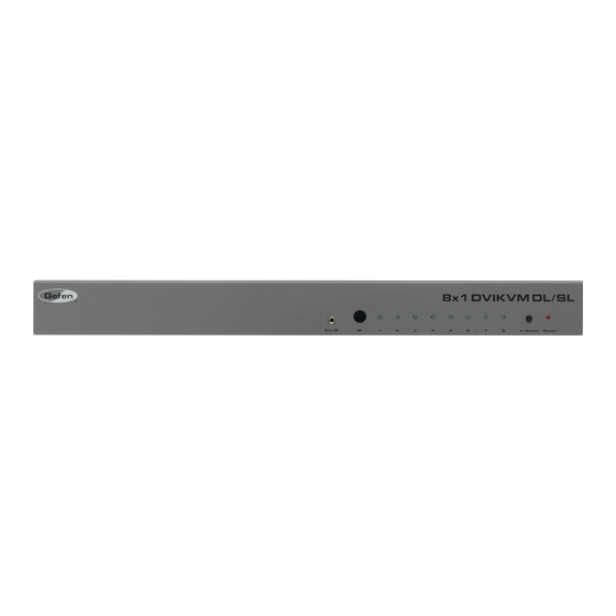
Page 7: Panel Layout
PANEL LAYOUT Front Panel Back Panel... -
Page 8: Panel Descriptions
PANEL DESCRIPTIONS External IR Port For connection of external IR extension device such as the Gefen IR Extender (part # EXT-RMT-EXTIR). IR Receiver Receives IR signal from the handheld Infrared remote control unit included with the 8x1 DVI KVM DL/SL Switcher. -
Page 9: Connecting & Operating The 8X1 Dvi Kvm Dl/Sl Switcher
CONNECTING & OPERATING THE 8X1 DVI KVM DL/SL SWITCHER How to Connect the 8x1 DVI KVM DL/SL Switcher to your devices: Connect your computers’ DVI, USB, and Audio sources to the 8x1 DVI KVM DL/SL Switcher inputs using the supplied cables. Connect your DVI display to the DVI output of the 8x1 DVI KVM DL/SL Switcher using a user-supplied DVI cable. -
Page 10: 8X1 Dvi Kvm Dl/Sl Remote Description
8X1 DVI KVM DL/SL REMOTE DESCRIPTION LED Indicator Input Selection Buttons The RMT-8IR remote control will allow the user to choose which of 8 DVI sources or computers will be selected. Please use the information below when selecting the desired source: RMT-8IR Button DVI Source... -
Page 11: 8X1 Dvi Kvm Dl/Sl Switcher Remote Installation
8X1 DVI KVM DL/SL SWITCHER REMOTE INSTALLATION To use the RMT-8IR remote, remove the battery cover on the back of the remote to reveal the battery compartment. Insert the included battery into the open battery slot. The positive (+) side should be facing up. Ensure that both DIP (Dual Inline Package) switches are in the OFF position. -
Page 12: Rmt-8Ir Remote And 8X1 Kvm Switcher Confi Guration
RMT-8IR REMOTE AND 8X1 KVM SWITCHER CONFIGURATION How to Resolve IR Code Confl icts In the event that IR commands from other remote controls confl ict with the supplied RMT-8IR remote control, changing the remote channel will alleviate this issue. The RMT-8IR remote control and the 8x1 DVI KVM DL/SL Switcher both have banks of DIP (Dual Inline Package) Switches for confi... -
Page 13: Edid Modes
EDID MODES EDID. What is it, and what is it used for? Under normal circumstances, a computer source device (digital or analog) will require information about a connected device/display to assess what resolutions and features (capabilities) are possible. The source device can then cater its output to create resolutions and/or features that are compatible with the attached device/display. - Page 14 EDID MODES EDID Modes The diagram below illustrates the 4 DIP switch bank. The 8 DIP switch bank functions are outlined later on this page. DIP SWITCH Function IR Channel IR Channel EDID Mode 1 2 3 4 Use DIP switch 3 to set the desired EDID mode. LOCAL EDID Mode (Switch 3=OFF) DEFAULT •...
-
Page 15: Dl (Dual Link) Only Modes
DL (DUAL LINK) ONLY MODES DL (Dual Link) Only Modes The 8 DIP switch bank, located on the underside of the 8x1 DVI KVM DL/SL Switcher cab be used to set each individual input to work in a Dual Link Only mode. -
Page 16: Rs-232 Serial Communication
RS-232 SERIAL COMMUNICATION What features are available via the RS-232 serial communications port? The 8x1 DVI KVM DL/SL Switcher can accept commands through the RS-232 serial communications port located on the rear panel. The current RS-232 control features are: • Switching/routing of inputs to outputs without the RMT-8IR remote control. -
Page 17: Rs-232 Serial Communication Commands
RS-232 SERIAL COMMUNICATION COMMANDS 1. ECHO PROTOCOL Defi nition: Semi echo mode – the product send echo every byte it received, except on receiving EDID fi le. Full echo mode – the product send echo every byte it received, even on receiving EDID fi... - Page 18 RS-232 SERIAL COMMUNICATION COMMANDS DS EDID store in Locals EDID This function reads EDID fi le from DS and store it in all input Locals EDID #EDIDDSTOLO DS EDID store in EDID Bank This function read EDID fi le from DS and store it in EDID bank #EDIDDSTOBA_param1\r Parameter Name...
- Page 19 RS-232 SERIAL COMMUNICATION COMMANDS Print EDID bank This function read EDID fi le from EDID bank and send it to the serial port. #PRBAEDID_param1_param2\r Parameter Name Value EDID bank offset [1 : 7 ] Send BIN fi le Send TXT fi le Load EDID to Locals EDID These function loads EDID fi...
-
Page 20: Rs-232 Serial Communication - Upload Edid
RS-232 SERIAL COMMUNICATION - UPLOAD EDID 3. HOW TO LOAD FILE WITH HYPER TERMINAL 3.1 HYPER TERMINAL SETTING File->Properties->Setting->ASCII Setup: Unmark the check box of “Send line ends with Line feeds” 3.2 SEND THE FILE Transfer->Send text fi le… Change “Files of type:” to “All fi les (*.*)” Open the fi... -
Page 21: Rack Mount Installation
RACK MOUNT INSTALLATION Rack mount ears are provided for installation of this unit into a 1U rack mount space. Locate the side screws on the unit. Remove the front 2 screws that are located closest to the front of the unit. Using the removed screws, screw the rack mounting bracket into the unit. -
Page 22: Specifi Cations
SPECIFICATIONS Video Amplifi er Bandwidth:..............165 MHz x 2 Input Video Signal:................1.2 Volts p-p Input DDC Signal:................5 Volts p-p (TTL) Maximum resolutions:....1920 x 1200 (single link), 3840x2400 (dual link) DVI Connector:............ DVI-I 29-pin female (digital only) USB Input Connection:................Type “B” USB Output Connection:................Type “A” Audio Connector:............ -
Page 23: Warranty
Gefen warrants the equipment it manufactures to be free from defects in material and workmanship. If equipment fails because of such defects and Gefen is notifi ed within two (2) years from the date of shipment, Gefen will, at its option, repair or replace the equipment, provided that the equipment has not been subjected to mechanical, electrical, or other abuse or modifi... - Page 26 Rev A3 20600 Nordhoff St., Chatsworth CA 91311 1-800-545-6900 818-772-9100 fax: 818-772-9120 www.gefen.com support@gefen.com...
Need help?
Do you have a question about the EXT-DVIKVM-841DL and is the answer not in the manual?
Questions and answers