Table of Contents
Advertisement
Quick Links
Advertisement
Table of Contents

Related Manuals for Gefen EXT-DVIKVM-241DL


Summary of Contents for Gefen EXT-DVIKVM-241DL
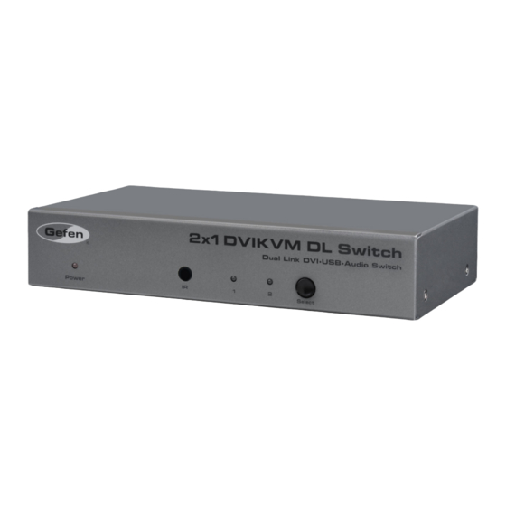
- Page 1 ® 2x1 DVIKVM DL Switch EXT-DVIKVM-241DL User Manual www.gefen.com...
- Page 3 Notice Gefen LLC reserves the right to make changes in the hardware, packaging, and any accompanying documentation without prior written notice. 2x1 DVIKVM DL Switch is a trademark of Gefen LLC © 2014 Gefen, LLC. All rights reserved.
-
Page 4: Table Of Contents
CONTENTS Introduction Operation Notes Features Panel Layout Panel Descriptions IR Remote Control Layout and Descriptions Installing the Battery Setting the IR channel Connecting the 2x1 DVIKVM DL Switch Wiring Diagram Operating the 2x1 DVIKVM DL Switch Switching sources Switching using the IR Remote Control Switching using the RMT2 Contact Closure Modes Setting the IR channel on the 2x1 DVIKVM DL Switch... -
Page 5: Introduction
INTRODUCTION Congratulations on your purchase of the Gefen 2X1 DVIKVM DL Switch. Your complete satisfaction is very important to us. Gefen Gefen delivers innovative, progressive computer and electronics add-on solutions that harness integration, extension, distribution and conversion technologies. Gefen’s reliable, plug-and-play products supplement cross-platform computer systems, professional audio/video environments and HDTV systems of all sizes with hard-working solutions that are easy to implement and simple to operate. -
Page 6: Operation Notes
When turning on or rebooting your computers, the DVI DL Switcher must be selected to the computer that is booting until the computer completes the boot cycle. This step can be eliminated using the Gefen DVI Detective, which stores the displays EDID. -
Page 7: Features
FEATURES Features • Switches easily between any two DVI computers with USB 2.0 and audio • Maintains highest resolution dual link video • Saves time and increase your productivity • Use either PC or Mac USB 2.0 keyboard/mouse • Front panel switching • Parallel remote port (RMT-2 not included) • Supports resolutions up to 1080p Full HD,1920 x 1200, 2K, and 3840 x 2400 • Supports DDWG standards for DVI monitors Includes: (1) 2X1 DVIKVM DL Switch (2) 6 ft. Dual Link DVI cables (2) 6 ft. USB cables (2) 3.5mm mini-stereo audio cables (1) IR Remote Control unit (1) 5V DC Power Supply (1) Quick Start Guide... -
Page 8: Panel Layout
PANEL LAYOUT... -
Page 9: Panel Descriptions
PANEL DESCRIPTIONS Power This LED will glow bright red once the included 5V DC locking power supply has been connected and plugged into an available electrical outlet. IR Sensor Receives IR commands from the included IR Remote Control Unit. Source Selection Indicators These LED indicators will glow bright blue depending upon which input source is selected. -
Page 10: Ir Remote Control
IR REMOTE CONTROL Layout and Descriptions LED Indicator This LED will be activated momentarily each time one of the two buttons are pressed. Input Selection Press these buttons to select the input source. NOTE: An Activity Indicator that flashes quickly while holding down any one of the two buttons indicates a low battery. Replace the IR Remote Control battery as soon as possible. -
Page 11: Installing The Battery
IR REMOTE CONTROL Installing the Battery The Remote Control unit ships with two batteries. One battery is required for operation and the other battery is a spare. Remove the battery cover on the back of the IR Remote Control unit. Insert the included battery into the open battery slot. The positive (+) side of the battery should be facing up. -
Page 12: Connecting The 2X1 Dvikvm Dl Switch
Plug the AC power cord from the power supply to an available electrical outlet. Wiring Diagram for the 2X1 DVIKVM DL Switch DVI (SL /DL) CABLE MINI STEREO AUDIO CABLE USB CABLE Computer Display Computer w/USB & Audio DVI KVM Switcher Powered Speakers EXT-DVIKVM-241DL... -
Page 13: Operating The 2X1 Dvikvm Dl Switch
OPERATING THE 2X1 DVIKVM DL SWITCH Switching sources Use the Select button on the front panel or the included IR Remote Control unit to switch between sources. Switching using the front panel • Press the Select button on the front panel to toggle between input 1 (DVI In 1) and input 2 (DVI In 2). -
Page 14: Switching Using The Rmt2
OPERATING THE 2X1 DVIKVM DL SWITCH Switching using the RMT2 (not included) Connect the RMT2 Remote (Gefen part no. EXT-RMT-2) to the Remote jack on the 2X1 DVIKVM DL Switch, using the included 3.5mm mini-stereo cable. Press the button on the front of the RMT2 Remote to switch between DVI In 1 and DVI In 2. -
Page 15: Contact Closure Modes
OPERATING THE 2X1 DVIKVM DL SWITCH Contact Closure Modes The 2x1 DVIKVM DL Switch provides two contact-closure modes: Discrete and Toggle modes. • Toggle mode In toggle mode, the 2x1 DVIKVM DL Switch uses the RMT2 (not included) to switch between DVI inputs. •... - Page 16 OPERATING THE 2X1 DVIKVM DL SWITCH Locate DIP switch 3. By default, this DIP switch will be in the OFF (down) position. DIP 3 in the OFF position Adjust DIP switch 3 to the desired position. DIP switch 3 Mode OFF (default) Toggle mode Discrete mode...
-
Page 17: Setting The Ir Channel On The 2X1 Dvikvm Dl Switch
DIP switch 4 to the ON position. Set DIP 4 to the ON position Connect the IR Extender (Gefen part no. EXT-RMT-EXTIR) to the Remote jack on the 2x1 DVIKVM DL Switch. Point the IR Remote Control unit at the IR Extender to control the 2x1... -
Page 18: Specifications
SPECIFICATIONS Maximum Pixel Clock................165 MHz Video Input Connectors......... (2) DVI-I 29 pin, female (digital only) Video Output Connector.........(1) DVI-I 29 pin, female (digital only) Audio Input Connectors..........(2) 3.5 mm mini-stereo jack Audio Output Connector..........(1) 3.5 mm mini-stereo jack USB Host Connectors............ -
Page 19: Warranty
WARRANTY Gefen warrants the equipment it manufactures to be free from defects in material and workmanship. If equipment fails because of such defects and Gefen is notified within two (2) years from the date of shipment, Gefen will, at its option, repair or replace the equipment, provided that the equipment has not been subjected to mechanical, electrical, or other abuse or modifications. Equipment that fails under conditions other than those covered will be repaired at the current price of parts and labor in effect at the time of repair. Such repairs are warranted for ninety (90) days from the day of reshipment to the Buyer. - Page 20 Rev A5 This product uses UL or CE listed power supplies.
Need help?
Do you have a question about the EXT-DVIKVM-241DL and is the answer not in the manual?
Questions and answers