Table of Contents
Advertisement
Quick Links
Advertisement
Table of Contents

Related Manuals for Crystal Image Technologies RM-FD117A


Summary of Contents for Crystal Image Technologies RM-FD117A
- Page 1 LCD Drawer User Manual RM-FD117A - 1 -...
- Page 2 This manual, covering various aspects of the equipment such as installation, setup and cascade, will help you make full use of this LCD Drawer. Please read this manual carefully and install and operate the equipment according to the manual to avoid damage to this product its accessories.
-
Page 3: Table Of Contents
Table of Contents Introduction …………………………………………………………………………-4- 1.1Overview…………………………………………………………………...…. -4- 1.2 Functions & Features…………………………………… ……………...…..-4- 1.3 Hardware Requirement……………………………………………..….……-4- 1.3.1 Host Requirement………………………………………………..… -4- 1.3.2 Cables…………………………………………………………...….… -4- 1.4 Product Specifications………………………………………………..….…..-5- 1.5 LCD Specifications………………………………………………….…..……-5- 1.6 Front View………………………………………………………….…..……. -6- 1.7 Rear View……………………………………………………………..….…...-7- Installation……………………………………………………………………...……-8- 2.1 Rack Installation……………………………………………………………… -8- 2.2 Standard Installation……………….………………………………….……... -
Page 4: Introduction
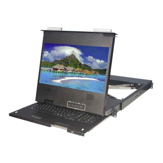
1 Introduction 1.1 Overview RM-DF117A LCD drawer integrates keyboard, LCD display and touch pad in a drawer type worktable and provides a convenient space-saving operation mode. The cover is an LCD display, while the base is keyboard and touchpad. RM-DF117A console is a control device integrating 17.3” LCD, 104 keys keyboard and touchpad mouse. -
Page 5: Product Specifications
1.4 Product Specifications Model RM-DF117A Brightness 300cd/m2 Contrast 650:1 Angle of visibility 140°(H),120°(V) Color display 262K 104 keys Keyboard touch pad mouse Mouse USB 2.0 Local Control Keyboard/Mouse 24 pin DVI-D female connector Terminal DVI-D HD-15 female connector USB 2.0 For USB peripheral device Video resolution 1920 x 1200 @75Hz... -
Page 6: Front View
Front View Part Function Description Handle to adjust screen opsition LCD display Keyboard Touchpad LCD button to control Screen Display position and LCD OSD button image setting. Mounting bracket Install into rack cabinet USB2.0 HUB port - 6 -... -
Page 7: Rear View
Rear View Component Function Description AC Power port Standard IEC Type AC Inlet Power Switch Rock switch, turn on/off equipment main power. Audio port For audio function Connect to server or KVM. VGA port USB port Connect to server or KVM. DVI port Connect to server or KVM. -
Page 8: Installation
2 Installation 2.1 Rack Installation Step 1 Loosen screw A on both sides to slide out and remove the two rear slide rails. Rear Slide Rails Step 2 Attach the two rear slide rails to the rear vertical mounting rails of the rack cabinet using standard M6 cage nuts and screws. -
Page 9: Standard Installation
2.2 Standard Installation Please follow the installation drawing and instructions below for standard installation: * Please Shutdown the Power of Equipment Needs to be Connected * Please Pay Attention to Earthing of Equipment The standard installation is completed, and LCD KVM console can be powered on. Then power on connected hosts. -
Page 10: Lcd Kvm Console And Kvm Cascade Installation
2.3 LCD KVM Console and KVM Cascade Installation LCD KVM console port can be directly connector to another KVM Switch as cascade to Perform unified management all connected hosts. Please follow the installation drawing and instructions for standard installation: (1) Make sure to power off all equipment to be connected and existing equipment. (2) Switching slide switch on USB position (3) Use an USB / VGA cable to connected the LCD and KVM switch console port. -
Page 11: Lcd Osd Menu Setup
2.4 LCD OSD Menu Setup OSD Control buttons LCD OSD can establish and setup LCD display. Setup instructions of four buttons are as follows: Button Functions POWER Turn on or off the LCD Display Activate OSD menu, select a menu and press MENU key to confirm the MENU selection and enter the submenu. -
Page 12: Certificates
3 Certificates This product has been tested and is proved to meet requirements of Grade B electronic devices and specifications of Section 15 of FCC certification. Please observe following two conditions in operation that: (1) The equipment will not generate any harmful interruption. (2) If the equipment is interrupted, it may cause unnecessary operations.
Need help?
Do you have a question about the RM-FD117A and is the answer not in the manual?
Questions and answers