Table of Contents
Advertisement
Quick Links
Advertisement
Table of Contents

Subscribe to Our Youtube Channel
Summary of Contents for IEI Technology AFL3-W07A-BT
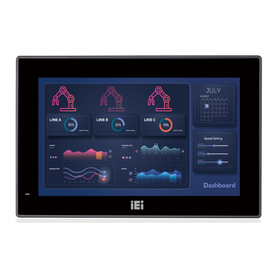
- Page 1 AFL3-W07A-BT Panel PC MODEL: AFL3-W07A-BT Flat Bezel Panel PC with Intel® Celeron® N2807 Dual-Core CPU, Touchscreen, Dual USB 3.0, Dual GbE LAN, Dual RS-232, HD Audio, Wi-Fi 802.11a/b/g/n/ac and RoHS User Manual User Manual Page I Rev. 1.05 - March 4, 2016...
- Page 2 AFL3-W07A-BT Panel PC Revision Date Version Changes March 4, 2016 1.05 Updated Table 1-1: System Specifications October 14, 2015 1.04 Changed touch controller Added Section 3.11: OS Installation Updated Chapter 4: BIOS Setup July 23, 2015 1.03 Updated Table 6-13: Webcam Connector (CAM_USB1) Pinouts June 30, 2015 1.02...
- Page 3 AFL3-W07A-BT Panel PC Copyright COPYRIGHT NOTICE The information in this document is subject to change without prior notice in order to improve reliability, design and function and does not represent a commitment on the part of the manufacturer. In no event will the manufacturer be liable for direct, indirect, special, incidental, or consequential damages arising out of the use or inability to use the product or documentation, even if advised of the possibility of such damages.
-
Page 4: Manual Conventions
AFL3-W07A-BT Panel PC Manual Conventions WARNING Warnings appear where overlooked details may cause damage to the equipment or result in personal injury. Warnings should be taken seriously. CAUTION Cautionary messages should be heeded to help reduce the chance of losing data or damaging the product. -
Page 5: Wall Mounting
AFL3-W07A-BT Panel PC 3.7.1 Wall Mounting To mount the flat bezel panel PC onto the wall, please follow the steps below. Step 1: Select the location on the wall for the wall-mounting bracket. Step 2: Carefully mark the locations of the four screw holes in the bracket on the wall. - Page 6 AFL3-W07A-BT Panel PC Step 6: Insert the four monitor mounting screws provided in the wall mount kit into the four screw holes on the real panel of the flat bezel panel PC and tighten until the screw shank is secured against the rear panel ( F igure 3-10).
- Page 7 AFL3-W07A-BT Panel PC Figure 3-10: Chassis Support Screws Step 9: Secure the panel PC by fastening the retention screw of the wall-mounting bracket. ( F igure 3-11). Figure 3-11: Secure the Panel PC Page 25...
-
Page 8: Panel Mounting
AFL3-W07A-BT Panel PC 3.7.2 Panel Mounting To mount the AFL3-W07A-BT flat bezel panel PC into a panel, please follow the steps below. Step 1: Select the position on the panel to mount the flat bezel panel PC. Step 2: Cut out a section corresponding to the size shown below. The size must be smaller then the outer edge. - Page 9 AFL3-W07A-BT Panel PC Step 5: Repeat Step 4 to install the other three screws into the sides of the two panel mounting brackets. Figure 3-13: Panel Mounting Kit Installation Align the panel mounting bracket screw holes with the VESA mounting holes on Step 6: the rear of the panel PC.
-
Page 10: Cabinet And Rack Installation
Figure 3-14: Securing Panel Mounting Brackets 3.7.3 Cabinet and Rack Installation The AFL3-W07A-BT flat bezel panel PC can be installed into a cabinet or rack. The installation procedures are similar to the panel mounting installation. To do this, please follow the steps below:... - Page 11 AFL3-W07A-BT Panel PC Figure 3-15: Rack/Cabinet Bracket Installation Insert a M5*50 screw into the screw hole on the side of the rack mounting Step 2: bracket. Then, install the following components onto the screw in sequence. See Figure 3-16. Sequence...
- Page 12 AFL3-W07A-BT Panel PC Figure 3-16: Rack Mounting Kit Installation Step 4: Align the rack mounting bracket screw holes with the VESA mounting holes on the rear of the panel PC. Secure the two rack mounting brackets to the rear of the panel PC by inserting...
- Page 13 AFL3-W07A-BT Panel PC Figure 3-17: Securing Rack Mounting Brackets Step 6: Slide the panel PC with the attached rack/cabinet bracket into a rack or cabinet (Figure 3-18). Figure 3-18: Install into a Rack/Cabinet Page 31...
-
Page 14: Arm Mounting
3.7.4 Arm Mounting The AFL3-W07A-BT is VESA (Video Electronics Standards Association) compliant and can be mounted on an arm with a 75 mm interface pad. To mount the AFL3-W07A-BT on an arm, please follow the steps below. The arm is a separately purchased item. Please correctly mount the arm onto Step 1: the surface it uses as a base. - Page 15 AFL3-W07A-BT Panel PC Figure 3-19: Arm Mounting Retention Screw Holes Step 4: Secure the AFL3-W07A-BT to the interface pad by inserting four retention screws through the mounting arm interface pad and into the AFL3-W07A-BT. S t e p 0 :...
-
Page 16: V-Stand Mounting
AFL3-W07A-BT Panel PC 3.7.5 Stand Mounting To mount the AFL3-W07A-BT using the stand mounting kit, please follow the steps below. Step 1: Locate the screw holes on the rear of the AFL3-W07A-BT. This is where the bracket will be attached. - Page 17 AFL3-W07A-BT Panel PC Figure 3-22: Drill Pilot Holes for V-Stand Step 2: Align the screw holes on the V-Stand with the VESA mount screw holes on the system rear panel. Step 3: Insert the four VESA mount screws into the four screw holes on the system rear panel.
-
Page 18: Powering On The System
Connect the power cord to the power adapter. Connect the other end of the power cord to a power source. Step 2: Connect the power adapter to the power connector of the AFL3-W07A-BT. Step 3: Locate the power button on the I/O panel.


Need help?
Do you have a question about the AFL3-W07A-BT and is the answer not in the manual?
Questions and answers