Table of Contents
Advertisement
Quick Links
Advertisement
Chapters
Table of Contents

Related Manuals for IEI Technology AFL3-W15B-H81


Summary of Contents for IEI Technology AFL3-W15B-H81
- Page 1 AFL3-W15B-H81 Panel PC MODEL: AFL3-W15B-H81 Flat Bezel Panel PC with Intel® H81 Chipset, Touchscreen, Dual GbE LAN, Wi-Fi 802.11a/b/g/n/ac, Dual USB 3.0, 2-Megapixel Camera and IP 64 Compliant Front Panel User Manual User Manual Page i Rev. 1.01 - March 1, 2017...
- Page 2 AFL3-W15B-H81 Panel PC Revision Date Version Changes March 1, 2017 1.01 Modified the brightness spec (page 6) July 1, 2015 1.00 Initial release Page ii...
- Page 3 AFL3-W15B-H81 Panel PC Copyright COPYRIGHT NOTICE The information in this document is subject to change without prior notice in order to improve reliability, design and function and does not represent a commitment on the part of the manufacturer. In no event will the manufacturer be liable for direct, indirect, special, incidental, or consequential damages arising out of the use or inability to use the product or documentation, even if advised of the possibility of such damages.
- Page 4 AFL3-W15B-H81 Panel PC Manual Conventions WARNING Warnings appear where overlooked details may cause damage to the equipment or result in personal injury. Warnings should be taken seriously. CAUTION Cautionary messages should be heeded to help reduce the chance of losing data or damaging the product.
-
Page 5: Table Of Contents
AFL3-W15B-H81 Panel PC Table of Contents 1 INTRODUCTION......................1 1.1 O ........................2 VERVIEW 1.2 M ....................2 ODEL ARIATIONS 1.3 F ........................3 EATURES 1.4 F ......................4 RONT ANEL 1.5 R ....................... 5 ANEL 1.6 B ......................5... - Page 6 AFL3-W15B-H81 Panel PC 3.12.2 Panel Mounting....................32 3.12.3 Cabinet and Rack Installation ............... 34 3.12.4 Arm Mounting ....................38 3.12.5 Stand Mounting ....................40 3.13 P ................... 41 OWERING N THE YSTEM 3.14 R ....................42 ESET THE YSTEM 3.15 S ..................
- Page 7 AFL3-W15B-H81 Panel PC 4.4 C ........................68 HIPSET 4.4.1 PCH-IO Configuration ..................69 4.4.1.1 PCI Express Configuration ............... 70 4.4.1.1.1 M_PCIE1/M-SATA and M_PCIE2............ 70 4.4.1.2 PCH Azalia Configuration ................ 72 4.4.2 System Agent (SA) Configuration ..............73 4.4.2.1 Graphics Configuration................74 4.4.2.1.1 LCD Control ..................
- Page 8 AFL3-W15B-H81 Panel PC 6.2.12 Power LED Connector (PW_LED1).............. 95 6.2.13 Power Button Connector (PW_BT1) ............. 95 6.2.14 SATA Signal and Power Connector (SATA1) ..........96 6.2.15 SMBus Connector (CN1) ................96 6.2.16 Speaker Connector (AUDIO_OUT1)............. 97 6.2.17 SPI Flash Connector (JSPI1)................. 97 6.2.18 TTL Serial Connector (NFC_COM4) ............
- Page 9 AFL3-W15B-H81 Panel PC C BIOS MENU OPTIONS....................116 D WATCHDOG TIMER ....................119 E HAZARDOUS MATERIALS DISCLOSURE ............122 Page ix...
- Page 10 AFL3-W15B-H81 Panel PC List of Figures Figure 1-1: AFL3-W15B-H81 Flat Bezel Panel PC................2 Figure 1-2: Front View ........................4 Figure 1-3: Rear View ........................5 Figure 1-4: Bottom Panel .......................6 Figure 1-5: AFL3-W15B-H81 Dimensions (mm)................9 Figure 1-6: AFL3-W15B-H81 with AFL3-2D-R10 Dimensions (mm).........10 Figure 3-1: AFL3-W15B-H81 Back Cover Retention Screws............19...
- Page 11 AFL3-W15B-H81 Panel PC Figure 3-26: Powering On the System..................41 Figure 3-27: Reset Button Location....................42 Figure 3-28: Keypad AP .......................43 Figure 3-29: Select Control Panel ....................43 Figure 3-30: Touchscreen Control Panel ...................44 Figure 3-31: Select Calibration Type ..................44 Figure 3-32: Calibration Window....................45 Figure 5-1: SO-DIMM Module Locations..................83...
- Page 12 AFL3-W15B-H81 Panel PC List of Tables Table 1-1: Model Variations ......................3 Table 1-2: System Specifications....................8 Table 3-1: COM1 DB-9 Serial Port Pin 9 Setting Jumper Settings...........23 Table 3-2: COM1_SEL1 Jumper Settings ...................24 Table 3-3: JP6 Jumper Settings ....................25 Table 3-4: Clear CMOS Jumper Settings..................26 Table 4-1: BIOS Navigation Keys ....................48...
- Page 13 AFL3-W15B-H81 Panel PC Table 6-25: VGA Connector (VGA_CON1) Pinouts ..............99 Table 6-26: Rear Panel Connectors ..................100 Table 6-27: GbE Connectors (LAN1 & LAN2) Pinouts ............100 Table 6-28: HDMI Connector (HDMI1) Pinouts................ 101 Table 6-29: Power Connector (PWR1) Pinouts............... 101 Table 6-30: RS-232 DB-9 Serial Port (COM2) Pinouts ............
- Page 14 AFL3-W15B-H81 Panel PC List of BIOS Menus BIOS Menu 1: Main ........................49 BIOS Menu 2: Advanced ......................50 BIOS Menu 3: ACPI Settings .......................51 BIOS Menu 4: RTC Wake Settings ....................52 BIOS Menu 5: CPU Configuration ....................53 BIOS Menu 6: SATA Configuration .....................55 BIOS Menu 7: Intel(R) Rapid Start Technology .................56...
-
Page 15: Introduction
AFL3-W15B-H81 Panel PC Chapter Introduction Page 1... -
Page 16: Overview
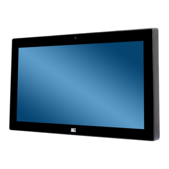
1.1 Overview Figure 1-1: AFL3-W15B-H81 Flat Bezel Panel PC The AFL3-W15B-H81 is a light industrial interactive panel PC with Intel® H81 chipset, providing optimal memory, graphics, and peripheral I/O support. The system comes with 4 GB of DDR3 SO-DIMM memory that can ensure smooth data throughputs with reduced bottlenecks and fast system access. -
Page 17: Features
AFL3-W15B-H81-i5/PC/4G-R10 2.7 GHz, max. TDP=35 W) Table 1-1: Model Variations 1.3 Features The AFL3-W15B-H81 features are listed below: Flat-bezel LCD with LED backlight Intel® Core™ i5-4570TE/Core™ i3-4330TE/Pentium® G3320TE processor Preinstalled with 4 GB of DDR3 memory (system max. 8 GB) -
Page 18: Front Panel
AFL3-W15B-H81 Panel PC 1.4 Front Panel The front side of the AFL3-W15B-H81 is a flat-bezel panel with a TFT LCD screen surrounded by a PC+ABS plastic frame (Figure 1-2). Figure 1-2: Front View There is a power LED indicator located on the front panel. The status descriptions of the power LED indicator are listed below. -
Page 19: Rear Panel
See Figure 1-3. Figure 1-3: Rear View 1.6 Bottom Panel The bottom panel of the AFL3-W15B-H81 has the following I/O interfaces (Figure 1-4): 1 x 9 V ~ 30 V DC power input connector, 4-pin 1 x AT/ATX switch 1 x Audio line-out jack... -
Page 20: System Specifications
AFL3-W15B-H81 Panel PC Figure 1-4: Bottom Panel 1.7 System Specifications The technical specifications for the AFL3-W15B-H81 systems are listed in Table 1-2. Specifications AFL3-W15B-H81 15.6” LCD Size 1366 x 768 (16:9) Max. Resolution Brightness (cd/m 700:1 Contrast Ratio 262K LCD Color 0.240 (H) x 0.240 (V) - Page 21 AFL3-W15B-H81 Panel PC Intel® Core™ i5-4570TE/Core™ i3-4330TE/ Pentium® G3320TE processor (max. TDP=35 W) Two 204-pin 1333 MHz single-channel DDR3 SO-DIMM slots (system max. 8 GB) Memory Preinstalled with 4 GB of DDR3 memory Two Realtek RTL8111E PCIe GbE controllers Ethernet...
-
Page 22: Table 1-2: System Specifications
AFL3-W15B-H81 Panel PC Cut-out Dimensions 369 mm x 226 mm (W x H) -20ºC ~ 50ºC (ambient with air flow) Operating Temperature -20ºC ~ 60ºC Storage Temperature 10% ~ 95% (non-condensing) Humidity IP 64 compliant front panel IP Level 96 W power adapter... -
Page 23: Dimensions
AFL3-W15B-H81 Panel PC 1.8 Dimensions The AFL3-W15B-H81 dimensions are shown below. Figure 1-5: AFL3-W15B-H81 Dimensions (mm) Page 9... -
Page 24: Figure 1-6: Afl3-W15B-H81 With Afl3-2D-R10 Dimensions (Mm)
AFL3-W15B-H81 Panel PC The dimensions of AFL3-W15B-H81 with AFL3-2D-R10 (optional barcode reader) are shown below. Figure 1-6: AFL3-W15B-H81 with AFL3-2D-R10 Dimensions (mm) Page 10... -
Page 25: Unpacking
AFL3-W15B-H81 Panel PC Chapter Unpacking Page 11... -
Page 26: Unpacking
AFL3-W15B-H81 Panel PC 2.1 Unpacking To unpack the flat bezel panel PC, follow the steps below: WARNING! The front side LCD screen has a protective plastic cover stuck to the screen. Only remove the plastic cover after the flat bezel panel PC has been properly installed. -
Page 27: Packing List
Contact the IEI reseller or vendor the AFL3-W15B-H81 was purchased from or contact an IEI sales representative directly by sending an email to ales@ieiworld.com. The AFL3-W15B-H81 flat bezel panel PC is shipped with the following components: Quantity Item Image... -
Page 28: Optional Items
AFL3-W15B-H81 Panel PC One Key Recovery CD 2.3 Optional Items The following are optional components which may be separately purchased: Item and Part Number Image Wall mounting kit (P/N: AFLWK-19B) Panel mounting kit (P/N: AFL3PK-W07A-R10) Rack mounting kit (P/N: AFL3RK-W15B-R10) - Page 29 AFL3-W15B-H81 Panel PC Item and Part Number Image Stand (P/N: STAND-A21-R10) Stand (P/N: STAND-210-R11) Stand (P/N: STAND-A19-RS) Stand (P/N: STAND-C19-R10) Barcode scanner (P/N: AFL3-2D-R10) Magnetic stripe card reader (P/N: AFL3P-12MSR-U-R10) RFID reader, 13.56 MHz Mifare type (IEI ATO only) (P/N: AFL3-MF-RFID-KIT02-R10)
- Page 30 AFL3-W15B-H81 Panel PC Item and Part Number Image OS: Windows 7 Embedded (for resistive touchscreen) (P/N: AFL3-W15B-H81-WES7E64-R10) OS: Windows 8 Embedded (P/N: AFL3-W15B-H81-WE8S-R10) Page 16...
-
Page 31: Installation
AFL3-W15B-H81 Panel PC Chapter Installation Page 17... -
Page 32: Anti-Static Precautions
AFL3-W15B-H81 and severe injury to the user. Electrostatic discharge (ESD) can cause serious damage to electronic components, including the AFL3-W15B-H81. Dry climates are especially susceptible to ESD. It is therefore critical that whenever the AFL3-W15B-H81 is accessed internally, or any other... -
Page 33: Installation And Configuration Steps
Step 5: Step 0: 3.4 Removing the Back Cover To access the AFL3-W15B-H81 internally, the back cover must be removed. To remove the back cover, please follow the steps below. Remove the four retention screws from the back cover. Step 1:... -
Page 34: Hdd Installation
Over-tightening back cover screws will crack the plastic frame. Maximum torque for cover screws is 5 kg-cm (0.36 lb-ft/0.49 Nm). 3.5 HDD Installation To install the HDD into the AFL3-W15B-H81, please follow the steps below: Remove the back cover. Refer to Section 3.4. Step 1:... -
Page 35: Figure 3-3: Hdd Bracket Retention Screws
AFL3-W15B-H81 Panel PC Figure 3-3: HDD Bracket Retention Screws Attach the HDD brackets to the HDD. To do this, align the four retention screw Step 3: holes from the bottom of the HDD bracket with the retention screw holes on bottom of the HDD. -
Page 36: Msata Module Installation
Step 6: Step 0: 3.6 mSATA Module Installation To install an mSATA module into the AFL3-W15B-H81, please follow the steps below: Remove the back cover. Refer to Section 3.4. Step 1: Locate the mSATA slot (M_PCIE1) on the motherboard. Remove the preinstalled Step 2: retention screw on the screw pillar of the PCIe Mini slot as shown in (Figure 3-6). -
Page 37: Com1 Db-9 Serial Port Pin 9 Selection
AFL3-W15B-H81 Panel PC Line up the notch on the mSATA module with the notch on the connector. Slide Step 3: the mSATA module into the socket at an angle of about 20º (Figure 3-7). Press the other end of the mSATA module down and secure the module with the Step 4: previously removed retention screw (Figure 3-7). -
Page 38: Or Rs-422/485 Selection For Com1 Serial Port
AFL3-W15B-H81 Panel PC The COM1 DB-9 serial port pin 9 setting jumper location is shown in Figure 3-8 below. Figure 3-8: COM1 DB-9 Serial Port Pin 9 Setting Jumper Location 3.8 RS-232 or RS-422/485 Selection for COM1 Serial Port The COM1_SEL1 jumper sets the communication protocol used by the COM1 serial communications port as RS-232 or RS-422/485. -
Page 39: Or Rs-485 Selection For Com1 Serial Port
AFL3-W15B-H81 Panel PC The COM1_SEL1 jumper location is shown in Figure 3-9. Figure 3-9: COM1_SEL1 Jumper Location 3.9 RS-232, RS-422 or RS-485 Selection for COM1 Serial Port The JP6 jumper sets the communication protocol used by the COM1 serial communication port as RS-232, RS-422 or RS-485. -
Page 40: Clear Cmos
Figure 3-10: JP6 Jumper Location 3.10 Clear CMOS If the AFL3-W15B-H81 fails to boot due to improper BIOS settings, the clear CMOS jumper clears the CMOS data and resets the system BIOS information. To reset the BIOS, move the jumper to the "Clear CMOS" position for 3 seconds or more, and then move back to the default position. -
Page 41: At/Atx Mode Selection
Figure 3-11: Clear CMOS Jumper Location 3.11 AT/ATX Mode Selection AT or ATX power mode can be used on the AFL3-W15B-H81. The selection is made through an AT/ATX switch located on the bottom panel (Figure 3-12). Figure 3-12: AT/ATX Switch Location... -
Page 42: At Power Mode
Manufacturing shop flow 3.11.2 ATX Power Mode With the ATX mode selected, the AFL3-W15B-H81 panel PC goes in a standby mode when it is turned off. The panel PC can be easily turned on via network or a power switch in standby mode. -
Page 43: Wall Mounting
AFL3-W15B-H81 Panel PC 3.12.1 Wall Mounting To mount the flat bezel panel PC onto the wall, please follow the steps below. Select the location on the wall for the wall-mounting bracket. Step 1: Carefully mark the locations of the four screw holes in the bracket on the wall. - Page 44 AFL3-W15B-H81 Panel PC Insert the four monitor mounting screws provided in the wall mount kit into the Step 6: four screw holes on the real panel of the flat bezel panel PC and tighten until the screw shank is secured against the rear panel (Figure 3-14).
-
Page 45: Figure 3-14: Chassis Support Screws
AFL3-W15B-H81 Panel PC Figure 3-14: Chassis Support Screws Secure the panel PC by fastening the retention screw of the wall-mounting Step 9: bracket (Figure 3-15). Figure 3-15: Secure the Panel PC Page 31... -
Page 46: Panel Mounting
AFL3-W15B-H81 Panel PC 3.12.2 Panel Mounting To mount the AFL3-W15B-H81 flat bezel panel PC into a panel, please follow the steps below. Select the position on the panel to mount the flat bezel panel PC. Step 1: Cut out a section corresponding to the size shown below. The size must be Step 2: smaller then the outer edge. -
Page 47: Figure 3-17: Panel Mounting Kit Installation
AFL3-W15B-H81 Panel PC Repeat to install the other three screws into the sides of the two panel Step 5: Step 4 mounting brackets. Figure 3-17: Panel Mounting Kit Installation Align the panel mounting bracket screw holes with the VESA mounting holes on Step 6: the rear of the panel PC. -
Page 48: Cabinet And Rack Installation
Figure 3-18: Securing Panel Mounting Brackets 3.12.3 Cabinet and Rack Installation The AFL3-W15B-H81 flat bezel panel PC can be installed into a cabinet or rack. The installation procedures are similar to the panel mounting installation. To do this, please follow the steps below:... -
Page 49: Figure 3-19: Rack/Cabinet Bracket Installation
AFL3-W15B-H81 Panel PC Figure 3-19: Rack/Cabinet Bracket Installation Insert a M5*50 screw into the screw hole on the side of the rack mounting Step 2: bracket. Then, install the following components onto the screw in sequence. See Figure 3-20. Sequence... -
Page 50: Figure 3-20: Rack Mounting Kit Installation
AFL3-W15B-H81 Panel PC Figure 3-20: Rack Mounting Kit Installation Align the rack mounting bracket screw holes with the VESA mounting holes on Step 4: the rear of the panel PC. Secure the two rack mounting brackets to the rear of the panel PC by inserting... -
Page 51: Figure 3-21: Securing Rack Mounting Brackets
AFL3-W15B-H81 Panel PC Figure 3-21: Securing Rack Mounting Brackets Slide the flat bezel panel PC with the attached rack/cabinet bracket into a rack or Step 6: cabinet (Figure 3-22). Figure 3-22: Install into a Rack/Cabinet Page 37... -
Page 52: Arm Mounting
When purchasing the arm please ensure that it is VESA compliant and that the arm has a 75 mm a 100 mm interface pad. If the mounting arm is not VESA compliant it cannot be used to support the AFL3-W15B-H81 flat bezel panel PC. -
Page 53: Figure 3-23: Arm Mounting Retention Screw Holes
AFL3-W15B-H81 Panel PC Figure 3-23: Arm Mounting Retention Screw Holes Secure the AFL3-W15B-H81 to the interface pad by inserting four retention Step 4: screws through the mounting arm interface pad and into the AFL3-W15B-H81. S t e p 0 :... -
Page 54: Stand Mounting
3.12.5 Stand Mounting To mount the AFL3-W15B-H81 using the stand mounting kit, please follow the steps below. Locate the screw holes on the rear of the AFL3-W15B-H81. This is where the Step 1: bracket will be attached. Align the bracket with the screw holes. -
Page 55: Powering On The System
3.13 Powering On the System To power on the system, follow the steps below: Connect the power adapter to the power connector of the AFL3-W15B-H81. Step 1: Connect the power cord to the power adapter. Connect the other end of the Step 2: power cord to a power source. -
Page 56: Reset The System
AFL3-W15B-H81 Panel PC 3.14 Reset the System The reset button enables user to reboot the system when the system is turned on. The reset button location is shown in Figure 3-27. Press the reset button to reboot the system. Figure 3-27: Reset Button Location 3.15 Software Installation... -
Page 57: Keypad Ap
AFL3-W15B-H81 Panel PC 3.15.1 Keypad AP Keypad AP is an OSD control tool developed by IEI. After the installation, the Keypad AP can be accessed by clicking the icon on the Windows notification area. It allows users to control screen brightness and audio volume. -
Page 58: Figure 3-30: Touchscreen Control Panel
AFL3-W15B-H81 Panel PC Figure 3-30: Touchscreen Control Panel The user can click Standard Calibration or Advanced Calibration to proceed Step 4: with standard or advanced calibration. Figure 3-31: Select Calibration Type Page 44... -
Page 59: Figure 3-32: Calibration Window
AFL3-W15B-H81 Panel PC The calibration window in Figure 3-32 appears. The user is asked to touch the Step 5: screen at five specified points, if Standard Calibration is selected. Follow the screen guide to touch and hold each red square in the calibration window until it shows “Lift off to proceed”. -
Page 60: Bios Setup
AFL3-W15B-H81 Panel PC Chapter BIOS Setup Page 46... -
Page 61: Introduction
AFL3-W15B-H81 Panel PC 4.1 Introduction The BIOS is programmed onto the BIOS chip. The BIOS setup program allows changes to certain system settings. This chapter outlines the options that can be changed. NOTE: Some of the BIOS options may vary throughout the life cycle of the product and are subject to change without prior notice. -
Page 62: Getting Help
AFL3-W15B-H81 Panel PC Function Page up Move to the next page Page down Move to the previous page Main Menu – Quit and do not save changes into CMOS Status Page Setup Menu and Option Page Setup Menu -- Exit current page and return to Main Menu... -
Page 63: Main
AFL3-W15B-H81 Panel PC 4.2 Main The Main BIOS menu (BIOS Menu 1) appears when the BIOS Setup program is entered. The Main menu gives an overview of the basic system information. Aptio Setup Utility – Copyright (C) 2012 American Megatrends, Inc. -
Page 64: Advanced
AFL3-W15B-H81 Panel PC The Main menu has two user configurable fields: System Date [xx/xx/xx] Use the System Date option to set the system date. Manually enter the day, month and year. System Time [xx:xx:xx] Use the System Time option to set the system time. Manually enter the hours, minutes and seconds. -
Page 65: Acpi Settings
AFL3-W15B-H81 Panel PC 4.3.1 ACPI Settings The ACPI Settings menu ( B IOS Menu 3) configures the Advanced Configuration and Power Interface (ACPI) options. Aptio Setup Utility – Copyright (C) 2012 American Megatrends, Inc. Advanced ACPI Settings Select the ACPI sleep state... -
Page 66: Rtc Wake Settings
AFL3-W15B-H81 Panel PC 4.3.2 RTC Wake Settings The RTC Wake Settings menu (BIOS Menu 4) enables the system to wake at the specified time. Aptio Setup Utility – Copyright (C) 2012 American Megatrends, Inc. Advanced Wake system with Fixed Time... -
Page 67: Cpu Configuration
AFL3-W15B-H81 Panel PC Wake up minute Wake up second After setting the alarm, the computer turns itself on from a suspend state when the alarm goes off. 4.3.3 CPU Configuration Use the CPU Configuration menu ( B IOS Menu 5) to view detailed CPU specifications and configure the CPU. -
Page 68: Active Processor Cores [All]
AFL3-W15B-H81 Panel PC Disables the Intel Hyper-Threading Technology. Disabled Enables the Intel Hyper-Threading Technology. Enabled EFAULT Active Processor Cores [All] Use the Active Processor Cores BIOS option to enable numbers of cores in the processor package. Enable all cores in the processor package. -
Page 69: Sata Configuration
AFL3-W15B-H81 Panel PC 4.3.4 SATA Configuration Use the SATA Configuration menu (BIOS Menu 6) to change and/or set the configuration of the SATA devices installed in the system. Aptio Setup Utility – Copyright (C) 2012 American Megatrends, Inc. Advanced SATA Controller(s) -
Page 70: Intel(R) Rapid Start Technology
AFL3-W15B-H81 Panel PC 4.3.5 Intel(R) Rapid Start Technology Use the Intel(R) Rapid Start Technology (BIOS Menu 7) menu to configure Intel® Rapid Start Technology support. Aptio Setup Utility – Copyright (C) 2012 American Megatrends, Inc. Advanced Intel(R) Rapid Start Technology... -
Page 71: Usb Configuration
AFL3-W15B-H81 Panel PC 4.3.6 USB Configuration Use the USB Configuration menu ( B IOS Menu 8) to read USB configuration information and configure the USB settings. Aptio Setup Utility – Copyright (C) 2012 American Megatrends, Inc. Advanced USB Configuration Enables Legacy USB support. -
Page 72: F81866 Super Io Configuration
AFL3-W15B-H81 Panel PC Legacy USB support enabled Enabled EFAULT Legacy USB support disabled Disabled Legacy USB support disabled if no USB devices are Auto connected 4.3.7 F81866 Super IO Configuration Use the F81866 Super IO Configuration menu ( B IOS Menu 9) to set or change the configurations for the serial ports. -
Page 73: Serial Port N Configuration
AFL3-W15B-H81 Panel PC 4.3.7.1 Serial Port n Configuration Use the Serial Port n Configuration menu (BIOS Menu 10) to configure the serial port n. Aptio Setup Utility – Copyright (C) 2012 American Megatrends, Inc. Advanced Serial Port n Configuration Enable or Disable Serial... -
Page 74: Serial Port 2 Configuration
AFL3-W15B-H81 Panel PC Serial Port I/O port address is 3F8h and the interrupt IO=3F8h; address is IRQ3, 4 IRQ=3, 4 Serial Port I/O port address is 2C0h and the interrupt IO=2C0h; address is IRQ3, 4 IRQ=3, 4 Serial Port I/O port address is 2C8h and the interrupt IO=2C8h;... -
Page 75: Touch Configuration
AFL3-W15B-H81 Panel PC The serial port IO port address and interrupt address Auto EFAULT are automatically detected. Serial Port I/O port address is 2F8h and the interrupt IO=2F8h; address is IRQ3 IRQ=3 Serial Port I/O port address is 3F8h and the interrupt IO=3F8h;... -
Page 76: F81866 H/W Monitor
AFL3-W15B-H81 Panel PC Serial Port I/O port address is 2E8h and the interrupt IO=2E8h; address is IRQ10, 11 IRQ=10, 11 Serial Port I/O port address is 2D8h and the interrupt IO=2D8h; address is IRQ10, 11 IRQ=10, 11 4.3.8 F81866 H/W Monitor... -
Page 77: Smart Fan Mode Configuration
AFL3-W15B-H81 Panel PC SYS_FAN1 Speed Voltages: CPU_CORE +12V +5VSB +3.3V +3.3VSB VBAT 4.3.8.1 Smart Fan Mode Configuration Use the Smart Fan Mode Configuration submenu (BIOS Menu 12) to configure fan speed settings. Aptio Setup Utility – Copyright (C) 2012 American Megatrends, Inc. -
Page 78: Serial Port Console Redirection
AFL3-W15B-H81 Panel PC The fan adjusts its speed using Auto Duty-Cycle Auto EFAULT Mode settings. Duty-Cycle Mode The fan spins at the speed set in Manual Duty Manual Duty Mode settings. Mode CPU Temperature 1/2/3/4 Use the + or – key to change the CPU Temperature 1/2/3/4 value. Enter a decimal number between 1 and 100. -
Page 79: Console Redirection Settings
AFL3-W15B-H81 Panel PC Console Redirection [Disabled] Use Console Redirection option to enable or disable the console redirection function. Disabled the console redirection function Disabled EFAULT Enabled the console redirection function Enabled 4.3.9.1 Console Redirection Settings Use the Console Redirection Settings menu ( B IOS Menu 14) to configure console redirection settings of the specified serial port. -
Page 80: Bits Per Second [115200]
AFL3-W15B-H81 Panel PC The target terminal type is VT-UTF8 VT-UTF8 The target terminal type is ANSI ANSI EFAULT Bits per second [115200] Use the Bits per second option to specify the serial port transmission speed. The speed must match the other side. Long or noisy lines may require lower speeds. -
Page 81: Iei Feature
AFL3-W15B-H81 Panel PC Stop Bits [1] Use the Stop Bits option to specify the number of stop bits used to indicate the end of a serial data packet. Communication with slow devices may require more than 1 stop bit. Sets the number of stop bits at 1. -
Page 82: Chipset
AFL3-W15B-H81 Panel PC 4.4 Chipset Use the Chipset menu ( B IOS Menu 16) to access the PCH and System Agent (SA) configuration menus. WARNING! Setting the wrong values for the Chipset BIOS selections in the Chipset BIOS menu may cause the system to malfunction. -
Page 83: Pch-Io Configuration
AFL3-W15B-H81 Panel PC 4.4.1 PCH-IO Configuration Use the PCH-IO Configuration menu ( B IOS Menu 17) to configure the PCH IO settings. Aptio Setup Utility – Copyright (C) 2012 American Megatrends, Inc. Chipset Auto Power Button Function [Disable (ATX)] Select AC power state when... -
Page 84: Pci Express Configuration
AFL3-W15B-H81 Panel PC 4.4.1.1 PCI Express Configuration Use the PCI Express Configuration menu (BIOS Menu 18) to configure the PCI Express slots. Aptio Setup Utility – Copyright (C) 2012 American Megatrends, Inc. Chipset PCI Express Configuration M_PCIE1/M-SATA Setting > M_PCIE1/M-SATA >... -
Page 85: Pcie Speed [Auto]
AFL3-W15B-H81 Panel PC PCIe Speed [Auto] Use this option to select the support type of the PCIe Mini slots. The following options are available: Auto Default Gen1 Gen2 Detect Non-Compliance Device [Disbled] Use the Detect Non-Compliance Device option to enable or disable detecting if a non-compliance PCI Express device is connected to the PCI Express slot. -
Page 86: Pch Azalia Configuration
AFL3-W15B-H81 Panel PC 4.4.1.2 PCH Azalia Configuration Use the PCH Azalia Configuration menu (BIOS Menu 20) to configure the PCH Azalia controller. Aptio Setup Utility – Copyright (C) 2012 American Megatrends, Inc. Chipset PCH Azalia Configuration Control Detection of the Azalia device. -
Page 87: System Agent (Sa) Configuration
AFL3-W15B-H81 Panel PC 4.4.2 System Agent (SA) Configuration Use the System Agent (SA) Configuration menu (BIOS Menu 21) to configure the System Agent (SA) parameters. Aptio Setup Utility – Copyright (C) 2012 American Megatrends, Inc. Chipset VT-d [Disabled] Check to enable VT-d function on MCH. -
Page 88: Graphics Configuration
AFL3-W15B-H81 Panel PC 4.4.2.1 Graphics Configuration Use the Graphics Configuration menu (BIOS Menu 22) to configure the graphics settings Aptio Setup Utility – Copyright (C) 2012 American Megatrends, Inc. Chipset Graphics Configuration Select which of IGFX/PEG/PCI Graphics Primary Display [Auto]... -
Page 89: Lcd Control
AFL3-W15B-H81 Panel PC 128M 256M EFAULT 512M DVMT Total Gfx Mem [MAX] Use the DVMT Total Gfx Mem option to specify the maximum amount of memory that can be allocated for the internal graphics device. Configuration options are listed below. -
Page 90: Memory Configuration
AFL3-W15B-H81 Panel PC Primary IGFX Boot Display [VBIOS Default] Use the Primary IGFX Boot Display option to select the display device used by the system when it boots. Configuration options are listed below. VBIOS Default EFAULT LVDS HDMI 4.4.2.2 Memory Configuration Use the Memory Configuration menu (BIOS Menu 24) to display the memory information. -
Page 91: Boot
AFL3-W15B-H81 Panel PC 4.5 Boot Use the Boot menu (BIOS Menu 25) to configure system boot options. Aptio Setup Utility – Copyright (C) 2012 American Megatrends, Inc. Main Advanced Chipset Boot Security Save & Exit Boot Configuration Select the keyboard... -
Page 92: Quiet Boot [Enabled]
AFL3-W15B-H81 Panel PC Quiet Boot [Enabled] Use the Quiet Boot BIOS option to select the screen display when the system boots. Normal POST messages displayed Disabled OEM Logo displayed instead of POST messages Enabled EFAULT Option ROM Messages [Force BIOS] Use the Option ROM Messages option to set the Option ROM display mode. -
Page 93: Security
AFL3-W15B-H81 Panel PC 4.6 Security Use the Security menu (BIOS Menu 26) to set system and user passwords. Aptio Setup Utility – Copyright (C) 2012 American Megatrends, Inc. Main Advanced Chipset Boot Security Save & Exit Password Description Set Administrator Password If ONLY the Administrator’s password is set,... -
Page 94: Bios Menu 27: Save & Exit
AFL3-W15B-H81 Panel PC Aptio Setup Utility – Copyright (C) 2012 American Megatrends, Inc. Main Advanced Chipset Boot Save & Exit Save Changes and Reset Exit the system after Discard Changes and Reset saving the changes. Restore Defaults Save as User Defaults... -
Page 95: System Maintenance
AFL3-W15B-H81 Panel PC Chapter System Maintenance Page 81... -
Page 96: System Maintenance Introduction
AFL3-W15B-H81 Panel PC 5.1 System Maintenance Introduction If the components of the AFL3-W15B-H81 fail they must be replaced. Please contact the system reseller or vendor to purchase the replacement parts. Back cover removal instructions for the AFL3-W15B-H81 are described in Section 3.4. -
Page 97: Turn Off The Power
AFL3-W15B-H81 Panel PC 5.3 Turn off the Power WARNING: Failing to turn off the system before opening it can cause permanent damage to the system and serious or fatal injury to the user. Before any maintenance procedures are carried out on the system, make sure the system is turned off. -
Page 98: Wlan Card Replacement
Step 7: Step 0: Figure 5-2: SO-DIMM Module Installation 5.5 WLAN Card Replacement The AFL3-W15B-H81 has one WLAN card slot. To replace the WLAN card, follow the instructions below. Follow all anti-static procedures. See Section 5.2. Step 1: Turn off the power. See Section 5.3. -
Page 99: Figure 5-3: Wlan Card Location
AFL3-W15B-H81 Panel PC Figure 5-3: WLAN Card Location Disconnect the antenna cables on the WLAN module and remove the retention Step 5: screw to release the WLAN card (Figure 5-4). Figure 5-4: Releasing the WLAN Card Grasp the WLAN card by the edges and carefully pull it out of the socket Step 6: (Figure 5-5). -
Page 100: Reinstalling The Cover
AFL3-W15B-H81 Panel PC Figure 5-5: Removing the WLAN Card Install a new WLAN card by inserting the card into the slot at an angle. Step 7: Push the WLAN card down and secure it with the previously removed retention Step 8: screw. -
Page 101: Interface Connectors
AFL3-W15B-H81 Panel PC Chapter Interface Connectors Page 87... -
Page 102: Peripheral Interface Connectors
AFL3-W15B-H81 Panel PC 6.1 Peripheral Interface Connectors The AFL3-W15B-H81 panel PC motherboard comes with a number of peripheral interface connectors and configuration jumpers. The connector locations are shown in F igure 6-1 and Figure 6-2. The Pin 1 locations of the on-board connectors are also indicated in the diagrams below. -
Page 103: Internal Peripheral Connectors
Internal peripheral connectors are found on the motherboard and are only accessible when the motherboard is outside of the chassis. The table below shows a list of the peripheral interface connectors on the motherboard of AFL3-W15B-H81. Pinouts of these connectors can be found in the following sections. -
Page 104: Battery Connector (Bat1)
AFL3-W15B-H81 Panel PC Connector Type Label MCU firmware connector 10-pin header Microphone connector 4-pin wafer DMIC1 PCIe Mini/mSATA slot Half-size PCIe Mini slot M_PCIE1 PCIe Mini slot Half-size PCIe Mini slot M_PCIE2 Power LED connector 3-pin wafer PW_LED1 Power button connector... -
Page 105: Digital I/O Connector (Dio1)
AFL3-W15B-H81 Panel PC 6.2.2 Digital I/O Connector (DIO1) PIN NO. DESCRIPTION PIN NO. DESCRIPTION DOUT3 DOUT2 DOUT1 DOUT0 DIN3 DIN2 DIN1 DIN0 Table 6-3: Digital I/O Connector (DIO1) Pinouts 6.2.3 Fan Connector (CPU_FAN1) PIN NO. DESCRIPTION PWM control signal Rotation signal... -
Page 106: Inverter Connector (Inverter1)
AFL3-W15B-H81 Panel PC VOL- BRIGHT+ BRIGHT1 LCD ON_OFF Table 6-6: Hotkey Connector (HOTKEY_CN1) Pinouts 6.2.6 Inverter Connector (INVERTER1) PIN NO. DESCRIPTION +12V +12V BRIGHTNESS ENABKL Table 6-7: Inverter Connector (INVERTER1) Pinouts 6.2.7 LVDS Connector (LVDS1) PIN NO. DESCRIPTION PIN NO. -
Page 107: Mcu Firmware Connector (Jp8)
AFL3-W15B-H81 Panel PC B_Y3 B_Y3# VCC/VCC3 VCC/VCC3 VCC/VCC3 VCC/VCC3 Table 6-8: LVDS Connector (LVDS1) Pinouts 6.2.8 MCU Firmware Connector (JP8) PIN NO. DESCRIPTION PIN NO. DESCRIPTION MCLR VCC3_MCU VCC5_MCU MCU_IR AUTO_CLK ICSPCLK AUTO_DATA ICSPDAT Table 6-9: MCU Firmware Connector (JP8) Pinouts 6.2.9 Microphone Connector (DMIC1) -
Page 108: Pcie Mini Slot (M_Pcie2)
AFL3-W15B-H81 Panel PC CLK+ PCIRST# VCC3 PCIRST# PERN (SATA_RX4+) 3VDual PERP (SATA_RX4-) 1.5V SMBCLK PETN (SATA_TX4-) SMBDATA PETP (SATA_TX4+) USBD10- USBD10+ SATA_DET4_R_N 1.5V MSATA_SEL# VCC3 Table 6-11: PCIe Mini/mSATA Slot (M_PCIE1) Pinouts 6.2.11 PCIe Mini Slot (M_PCIE2) PIN NO. DESCRIPTION PIN NO. -
Page 109: Power Led Connector (Pw_Led1)
AFL3-W15B-H81 Panel PC VCC3 PCIRST# PERN2 3VDual PERP2 1.5V SMBCLK PETN2 SMBDATA PETP2 USBD11- USBD11+ 1.5V MSATA_SEL# VCC3 Table 6-12: PCIe Mini Slot (M_PCIE2) Pinouts 6.2.12 Power LED Connector (PW_LED1) PIN NO. DESCRIPTION PW_LED +5V SUS PW LED +5V Table 6-13: Power LED Connector (PW_LED1) Pinouts 6.2.13 Power Button Connector (PW_BT1) -
Page 110: Sata Signal And Power Connector (Sata1)
AFL3-W15B-H81 Panel PC 6.2.14 SATA Signal and Power Connector (SATA1) PIN NO. DESCRIPTION PIN NO. DESCRIPTION VCC3 VCC3 VCC3 VCC5 VCC5 VCC5 VCC12 VCC12 VCC12 Table 6-15: SATA Signal and Power Connector (SATA1) Pinouts 6.2.15 SMBus Connector (CN1) PIN NO. -
Page 111: Speaker Connector (Audio_Out1)
AFL3-W15B-H81 Panel PC 6.2.16 Speaker Connector (AUDIO_OUT1) PIN NO. DESCRIPTION SPK_OUT_P_L SPK_OUT_N_L SPK_OUT_N_R SPK_OUT_P_R Table 6-17: Speaker Connector (AUDIO_OUT1) Pinouts 6.2.17 SPI Flash Connector (JSPI1) PIN NO. DESCRIPTION +V3.3M_SPI_CON SPI_CS#0_CN SPI_SO_SW SPI_CLK_SW SPI_SI_SW Table 6-18: SPI Flash Connector (JSPI1) Pinouts 6.2.18 TTL Serial Connector (NFC_COM4) -
Page 112: Usb Connector For Barcode Reader (Br_Usb1)
AFL3-W15B-H81 Panel PC 6.2.19 USB Connector for Barcode Reader (BR_USB1) PIN NO. DESCRIPTION HUB_D3F- HUB_D3F+ Table 6-20: USB Connector for Barcode Reader (BR_USB1) Pinouts 6.2.20 USB Connector for Bluetooth (BT_USB1) PIN NO. DESCRIPTION +3.3 HUB_D1F- HUB_D1F+ Table 6-21: USB Connector for Bluetooth (BT_USB1) Pinouts 6.2.21 USB Connector for Camera (CAM_USB1) -
Page 113: Usb Connector For Nfc (Nfc_Usb1)
AFL3-W15B-H81 Panel PC 6.2.22 USB Connector for NFC (NFC_USB1) PIN NO. DESCRIPTION HUB_D4F- HUB_D4F+ Table 6-23: USB Connector for NFC (NFC_USB1) Pinouts 6.2.23 USB Connector for Touchscreen (TOUCH_USB1) PIN NO. DESCRIPTION D8F- D8F+ Table 6-24: USB Connector for Touchscreen (TOUCH_USB1) Pinouts 6.2.24 VGA Connector (VGA_CON1) -
Page 114: External Interface Panel Connectors
AFL3-W15B-H81 Panel PC 6.3 External Interface Panel Connectors The table below lists the rear panel connectors on the motherboard of AFL3-W15B-H81. Pinouts of these connectors can be found in the following sections. Connector Type Label AT/ATX mode selection switch Switch... -
Page 115: Hdmi Connector (Hdmi1)
AFL3-W15B-H81 Panel PC 6.3.2 HDMI Connector (HDMI1) PIN NO. DESCRIPTION PIN NO. DESCRIPTION HDMI_DATA2+ HDMI_CLK# HDMI_DATA2#- HDMI_DATA1+ HDMI_SCL HDMI_DATA1#- HDMI_SDA HDMI_DATA0+ +5VCC HDMI_DATA0#- HDMI_HPD HDMI_CLK+ Table 6-28: HDMI Connector (HDMI1) Pinouts 6.3.3 Power Connector (PWR1) PIN NO. DESCRIPTION PIN NO. -
Page 116: Rs-232/422/485 Db-9 Serial Port (Com1)
AFL3-W15B-H81 Panel PC 6.3.5 RS-232/422/485 DB-9 Serial Port (COM1) PIN NO. DESCRIPTION PIN NO. DESCRIPTION -NDCD1 -NDSR1 NSIN1 -NRTS1 NSOUT1 -NCTS1 -NDTR1 -XRI1 Table 6-31: RS-232/422/485 DB-9 Serial Port (COM1) Pinouts 6.3.6 USB 2.0 Connectors (USB20_CN1) PIN NO. DESCRIPTION PIN NO. -
Page 117: Preconfigured Jumper Settings
3.0_RX2+ 3.0_TX2- 3.0_TX2+ Table 6-34: USB 3.0 Connectors (USB_CON1) Pinouts 6.4 Preconfigured Jumper Settings CAUTION: The following jumpers are preconfigured for the AFL3-W15B-H81. Users should not change these jumpers (Table 6-35). It is only for reference. Jumper Name Type Label... -
Page 118: Lvds Panel Voltage Selection Jumper (J_Vlvds1)
AFL3-W15B-H81 Panel PC 6.4.2 LVDS Panel Voltage Selection Jumper (J_VLVDS1) Description Short 1-2 +3.3V (Default) Short 3-4 Short 5-6 +12V Table 6-37: LVDS Panel Voltage Selection Jumper (J_VLVDS1) Settings Page 104... -
Page 119: A Regulatory Compliance
AFL3-W15B-H81 Panel PC Appendix Regulatory Compliance Page 105... - Page 120 AFL3-W15B-H81 Panel PC DECLARATION OF CONFORMITY This equipment is in conformity with the following EU directives: EMC Directive (2004/108/EC, 2014/30/EU) Low-Voltage Directive (2006/95/EC, 2014/35/EU) RoHS II Directive (2011/65/EU, 2015/863/EU) If the user modifies and/or install other devices in the equipment, the CE conformity declaration may no longer apply.
- Page 121 AFL3-W15B-H81 Panel PC Español [Spanish] IEI Integration Corp declara que el equipo cumple con los requisitos esenciales y cualesquiera otras disposiciones aplicables o exigibles de la Directiva 2014/53/EU. Ελληνική [Greek] IEI Integration Corp ΔΗΛΩΝΕΙ ΟΤΙ ΕΞΟΠΛΙΣΜΟΣ ΣΥΜΜΟΡΦΩΝΕΤΑΙ ΠΡΟΣ ΤΙΣ ΟΥΣΙΩΔΕΙΣ ΑΠΑΙΤΗΣΕΙΣ ΚΑΙ ΤΙΣ ΛΟΙΠΕΣ ΣΧΕΤΙΚΕΣ ΔΙΑΤΑΞΕΙΣ ΤΗΣ ΟΔΗΓΙΑΣ...
- Page 122 AFL3-W15B-H81 Panel PC Româna [Romanian] IEI Integration Corp declară că acest echipament este in conformitate cu cerinţele esenţiale şi cu celelalte prevederi relevante ale Directivei 2014/53/EU. Slovensko [Slovenian] IEI Integration Corp izjavlja, da je ta opreme v skladu z bistvenimi zahtevami in ostalimi relevantnimi določili direktive 2014/53/EU.
- Page 123 AFL3-W15B-H81 Panel PC FCC WARNING This equipment complies with Part 15 of the FCC Rules. Operation is subject to the following two conditions: This device may not cause harmful interference, and This device must accept any interference received, including interference that may cause undesired operation.
-
Page 124: B Safety Precautions
AFL3-W15B-H81 Panel PC Appendix Safety Precautions Page 110... -
Page 125: Safety Precautions
Electric shocks can occur if the AFL3-W15B-H81 chassis is opened when it is running. To avoid risk of electric shock, this device must only be connected to a supply mains with protective earth. -
Page 126: Anti-Static Precautions
Electrostatic discharge (ESD) can cause serious damage to electronic components, including the AFL3-W15B-H81. Dry climates are especially susceptible to ESD. It is therefore critical that whenever the AFL3-W15B-H81 is opened and any of the electrical components are handled, the following anti-static precautions are strictly adhered to. -
Page 127: Product Disposal
AFL3-W15B-H81 Panel PC B.1.3 Product Disposal CAUTION: Risk of explosion if battery is replaced by an incorrect type. Only certified engineers should replace the on-board battery. Dispose of used batteries according to instructions and local regulations. Outside the European Union–If you wish to dispose of used electrical and electronic products outside the European Union, please contact your local authority so as to comply with the correct disposal method. -
Page 128: Maintenance And Cleaning Precautions
In such case, the product will be explicitly mentioned in the cleaning tips. Below is a list of items to use when cleaning the AFL3-W15B-H81. Cloth– Although paper towels or tissues can be used, a soft, clean piece of cloth is recommended when cleaning the device. - Page 129 AFL3-W15B-H81 Panel PC Water or rubbing alcohol–A cloth moistened with water or rubbing alcohol can be used to clean the device. Using solvents–The use of solvents is not recommended when cleaning the device as they may damage the plastic parts.
-
Page 130: C Bios Menu Options
AFL3-W15B-H81 Panel PC Appendix BIOS Menu Options Page 116... - Page 131 AFL3-W15B-H81 Panel PC System Date [xx/xx/xx] ......................50 System Time [xx:xx:xx] .......................50 ACPI Sleep State [S1 only (CPU Stop Clock)]..............51 Wake system with Fixed Time [Disabled]................52 Hyper-threading [Enabled]....................53 Active Processor Cores [All] ....................54 Intel Virtualization Technology [Disabled] ................54 ...
- Page 132 AFL3-W15B-H81 Panel PC Azalia (HD Audio) [Enabled] ....................72 VT-d [Disabled]........................73 Primary Display [Auto] ......................74 DVMT Pre-Allocated [256M] ....................74 DVMT Total Gfx Mem [MAX]....................75 Primary IGFX Boot Display [VBIOS Default] ..............76 Bootup NumLock State [On]....................77 ...
-
Page 133: D Watchdog Timer
AFL3-W15B-H81 Panel PC Appendix Watchdog Timer Page 119... - Page 134 AFL3-W15B-H81 Panel PC NOTE: The following discussion applies to DOS. Contact IEI support or visit the IEI website for drivers for other operating systems. The Watchdog Timer is a hardware-based timer that attempts to restart the system when it stops working. The system may stop working because of external EMI or software bugs.
- Page 135 AFL3-W15B-H81 Panel PC NOTE: The Watchdog Timer is activated through software. The software application that activates the Watchdog Timer must also deactivate it when closed. If the Watchdog Timer is not deactivated, the system will automatically restart after the Timer has finished its countdown.
-
Page 136: E Hazardous Materials Disclosure
AFL3-W15B-H81 Panel PC Appendix Hazardous Materials Disclosure Page 122... - Page 137 AFL3-W15B-H81 Panel PC The details provided in this appendix are to ensure that the product is compliant with the Peoples Republic of China (China) RoHS standards. The table below acknowledges the presences of small quantities of certain materials in the product, and is applicable to China RoHS only.
- Page 138 AFL3-W15B-H81 Panel PC 此附件旨在确保本产品符合中国 RoHS 标准。以下表格标示此产品中某有毒物质的含量符 合中国 RoHS 标准规定的限量要求。 本产品上会附有”环境友好使用期限”的标签,此期限是估算这些物质”不会有泄漏或突变”的 年限。本产品可能包含有较短的环境友好使用期限的可替换元件,像是电池或灯管,这些元 件将会单独标示出来。 部件名称 有毒有害物质或元素 铅 汞 镉 六价铬 多溴联苯 多溴二苯 醚 (Pb) (Hg) (Cd) (CR(VI)) (PBB) (PBDE) 壳体 显示 印刷电路板 金属螺帽 电缆组装 风扇组装 电力供应组装 电池 O: 表示该有毒有害物质在该部件所有物质材料中的含量均在 SJ/T 11363-2006 (现由 GB/T 26572-2011 取代) 标准规定的限量要求以下。...
Need help?
Do you have a question about the AFL3-W15B-H81 and is the answer not in the manual?
Questions and answers