Table of Contents
Advertisement
Quick Links
Advertisement
Chapters
Table of Contents

Related Manuals for IEI Technology AFL3-W07A-BT-N1/PC/2G-R20


Summary of Contents for IEI Technology AFL3-W07A-BT-N1/PC/2G-R20
- Page 1 AFL3-W07A-BT Panel PC MODEL: AFL3-W07A-BT Flat Bezel Panel PC with Intel® Celeron® N2807 Dual-Core CPU, Touchscreen, Dual USB 3.2 Gen 1, Dual GbE LAN, Dual RS-232, HD Audio, Wi-Fi 802.11a/b/g/n/ac and RoHS User Manual User Manual Page I Rev. 1.31 - May 25, 2020...
- Page 2 AFL3-W07A-BT Panel PC Revision Date Version Changes May 25, 2020 1.31 Updated spec. – operating temperature December 5, 2018 1.30 Updated for R13 version – upgraded to anti-glare touch screen March 4, 2016 1.05 Updated Table 1-1: System Specifications October 14, 2015 1.04 Changed touch controller Added Section 3.11: OS Installation...
- Page 3 AFL3-W07A-BT Panel PC Copyright COPYRIGHT NOTICE The information in this document is subject to change without prior notice in order to improve reliability, design and function and does not represent a commitment on the part of the manufacturer. In no event will the manufacturer be liable for direct, indirect, special, incidental, or consequential damages arising out of the use or inability to use the product or documentation, even if advised of the possibility of such damages.
- Page 4 AFL3-W07A-BT Panel PC Manual Conventions WARNING Warnings appear where overlooked details may cause damage to the equipment or result in personal injury. Warnings should be taken seriously. CAUTION Cautionary messages should be heeded to help reduce the chance of losing data or damaging the product. NOTE These messages inform the reader of essential but non-critical information.
-
Page 5: Table Of Contents
AFL3-W07A-BT Panel PC Table of Contents 1 INTRODUCTION ......................1 1.1 O ........................2 VERVIEW 1.2 F ........................3 EATURES 1.3 F ......................3 RONT ANEL 1.4 R ....................... 4 ANEL 1.5 B ......................4 OTTOM ANEL 1.6 S .................... 5 YSTEM PECIFICATIONS 1.7 D... - Page 6 AFL3-W07A-BT Panel PC 3.7.5 Stand Mounting ....................33 3.7.6 V-Stand Mounting .................... 33 3.8 P ..................35 OWERING N THE YSTEM 3.9 R ....................36 ESET THE YSTEM 3.10 C CMOS ......................37 LEAR 3.11 OS I ....................38 NSTALLATION 3.12 S ..................
- Page 7 AFL3-W07A-BT Panel PC 4.4.2.1 PCI Express Configuration ............... 64 4.5 S ......................... 65 ECURITY 4.6 B ........................66 4.7 S & E ......................68 5 SYSTEM MAINTENANCE ..................70 5.1 S ..............71 YSTEM AINTENANCE NTRODUCTION 5.2 A ..................71 STATIC RECAUTIONS 5.3 T...
- Page 8 AFL3-W07A-BT Panel PC B SAFETY PRECAUTIONS ..................92 B.1 S ..................... 93 AFETY RECAUTIONS B.1.1 General Safety Precautions ................93 B.1.2 Anti-static Precautions ..................94 B.1.3 Product Disposal ..................... 95 B.2 M ............95 AINTENANCE AND LEANING RECAUTIONS B.2.1 Maintenance and Cleaning ................95 B.2.2 Cleaning Tools ....................
- Page 9 AFL3-W07A-BT Panel PC List of Figures Figure 1-1: AFL3-W07A-BT Flat Bezel Panel PC ................. 2 Figure 1-2: Front View ........................3 Figure 1-3: Rear View ........................4 Figure 1-4: Bottom Panel ....................... 5 Figure 1-5: AFL3-W07A-BT Dimensions (mm) ................8 Figure 3-1: Back Cover Retention Screws .................
- Page 10 AFL3-W07A-BT Panel PC Figure 3-27: Clear CMOS Button Location ................. 37 Figure 3-28: BIOS Option–OS Selection ..................38 Figure 3-29: IEI Resource Download Center ................39 Figure 3-30: Keypad AP ....................... 41 Figure 5-1: Back Cover Retention Screws ................. 73 Figure 5-2: WLAN Card Location ....................
- Page 11 AFL3-W07A-BT Panel PC List of Tables Table 1-1: System Specifications ....................7 Table 6-1: BIOS Navigation Keys ....................44 Table 6-1: Peripheral Interface Connectors ................78 Table 6-2: Battery Connector (CN2) Pinouts ................78 Table 6-3: LVDS Connector (LVDS2) Pinouts ................79 Table 6-4: MCU Connector (JSPI2) Pinouts ................
- Page 12 AFL3-W07A-BT Panel PC List of BIOS Menus BIOS Menu 1: Main ........................45 BIOS Menu 2: Advanced ......................47 BIOS Menu 3: ACPI Settings ....................... 48 BIOS Menu 4: F81866 Super IO Configuration ................49 BIOS Menu 5: Serial Port n Configuration Menu ............... 49 BIOS Menu 6: F81866 H/W Monitor .....................
-
Page 13: Introduction
AFL3-W07A-BT Panel PC Chapter Introduction Page 1... -
Page 14: Overview
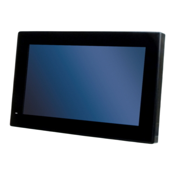
AFL3-W07A-BT Panel PC 1.1 Overview Figure 1-1: AFL3-W07A-BT Flat Bezel Panel PC The AFL3-W07A-BT is a dual-core Intel® Celeron® processor N2807 powered flat bezel panel PC with a rich variety of functions and peripherals. The compact design is ideal for easy and simplified integration into kiosk and point-of-sales (POS) applications. -
Page 15: Features
AFL3-W07A-BT Panel PC 1.2 Features The AFL3-W07A-BT features are listed below: 7" flat-bezel LCD with LED backlight Intel® Celeron® processor N2807 (1.58 GHz, dual-core) On-board 2 GB DDR3L memory 2-point anti-glare/anti-UV multi-touch projected capacitive type touchscreen Wi-Fi 802.11a/b/g/n/ac 1T1R high speed wireless ... -
Page 16: Rear Panel
AFL3-W07A-BT Panel PC Solid green: the system is turned on. 1.4 Rear Panel The rear panel provides access to retention screw holes that support VESA mounting. See Figure 1-5. Figure 1-3: Rear View 1.5 Bottom Panel The bottom panel of the AFL3-W07A-BT has the following connectors and switches (Figure 1-6): 1 x 9 V ~ 30 V DC input power jack ... -
Page 17: System Specifications
AFL3-W07A-BT Panel PC Figure 1-4: Bottom Panel 1.6 System Specifications The technical specifications for the AFL3-W07A-BT systems are listed in Table 1-4. Specification AFL3-W07A-BT LCD Size 7" (16:9) Max. Resolution 1024 (W) x 600 (H) Brightness (cd/m2) Contrast Ratio 700:1 LCD Color 16.2M Pixel Pitch (H x V) (mm) - Page 18 AFL3-W07A-BT Panel PC Memory On-board 1333 MHz 2 GB/4 GB DDR3L memory Storage One full-size PCIe Mini card slot for mSATA module installation Audio Realtek ALC892 HD Audio codec Speaker One 2 W stereo speaker (left channel output only) Wireless One 802.11a/b/g/n/ac 1T1R wireless LAN module (half-size PCIe Mini card) Bluetooth...
-
Page 19: Table 1-1: System Specifications
AFL3-W07A-BT Panel PC I/O Ports and Switches 2 x RS-232 (DB-9 connector) 2 x GbE LAN (RJ-45 connector) 2 x USB 3.2 Gen 1 (5Gb/s) connectors 1 x Power button 1 x AT/ATX switch 1 x Reset button 1 x 9 V ~ 30 V DC input jack Table 1-1: System Specifications Page 7... -
Page 20: Dimensions
AFL3-W07A-BT Panel PC 1.7 Dimensions The AFL3-W07A-BT dimensions are shown below. Width: 190.9 mm Height: 127.3 mm Depth: 43.4 mm Figure 1-5: AFL3-W07A-BT Dimensions (mm) Page 8... -
Page 21: Unpacking
AFL3-W07A-BT Panel PC Chapter Unpacking Page 9... -
Page 22: Unpacking
AFL3-W07A-BT Panel PC 2.1 Unpacking To unpack the flat bezel panel PC, follow the steps below: WARNING! The front side LCD screen has a protective plastic cover stuck to the screen. Only remove the plastic cover after the flat bezel panel PC has been properly installed. -
Page 23: Packing List
AFL3-W07A-BT Panel PC 2.2 Packing List The AFL3-W07A-BT flat bezel panel PC is shipped with the following components: Quantity Item Image AFL3-W07A-BT panel PC Power adapter (36 W) Power cord Screws for VESA mounting Screws for PCIe Mini card installation 2.3 Optional Items The following are optional components which may be separately purchased: Item and Part Number... - Page 24 AFL3-W07A-BT Panel PC Item and Part Number Image Rack mount kit (P/N: AFL3RK-W07A-R11) (P/N: ARM-11-RS) (P/N: ARM-31-RS) Stand for VESA 75 (P/N: STAND-B08) Stand (P/N:STAND-100-RS) LCD monitor stand with adjustable hinge (P/N: VSTAND-A07-R11) If any of these items are missing or damaged, contact the distributor or sales representative immediately.
-
Page 25: Installation
AFL3-W07A-BT Panel PC Chapter Installation Page 13... -
Page 26: Anti-Static Precautions
AFL3-W07A-BT Panel PC 3.1 Anti-static Precautions WARNING: Failure to take ESD precautions during the maintenance of the AFL3-W07A-BT result permanent damage AFL3-W07A-BT and severe injury to the user. Electrostatic discharge (ESD) can cause serious damage to electronic components, including the AFL3-W07A-BT. Dry climates are especially susceptible to ESD. It is therefore critical that whenever the AFL3-W07A-BT is accessed internally, or any other electrical component is handled, the following anti-static precautions are strictly adhered Wear an anti-static wristband: - Wearing a simple anti-static wristband can... -
Page 27: Installation And Configuration Steps
AFL3-W07A-BT Panel PC Anti-static Discharge: If a user open the rear panel of the flat bezel panel PC, to configure the jumpers or plug in added peripheral devices, ground themselves first and wear an anti-static wristband. 3.3 Installation and Configuration Steps The following installation steps must be followed. -
Page 28: Figure 3-1: Back Cover Retention Screws
AFL3-W07A-BT Panel PC Figure 3-1: Back Cover Retention Screws Step 2: Remove the back cover from the device. See Figure 3-2. Figure 3-2: Open the Back Cover Step 3: Locate the full-size PCIe Mini card slot. Remove the preinstalled retention screw on the screw pillar of the PCIe Mini card slot as shown in (Figure 3-3). -
Page 29: Figure 3-3: Msata Module Slot Location
AFL3-W07A-BT Panel PC Figure 3-3: mSATA Module Slot Location Step 4: Line up the notch on the mSATA module with the notch on the connector. Slide the PCIe Mini card into the socket at an angle of about 20º. Step 5: Secure the mSATA module with the retention screw. -
Page 30: At/Atx Mode Selection
AFL3-W07A-BT Panel PC 3.5 AT/ATX Mode Selection AT or ATX power mode can be used on the AFL3-W07A-BT. The selection is made through an AT/ATX switch located on the bottom panel (Figure 3-5). Figure 3-5: AT/ATX Switch Location 3.5.1 AT Power Mode With the AT mode selected, the power is controlled by a central power unit rather than a power switch. -
Page 31: External Peripheral Device Connection
AFL3-W07A-BT Panel PC 3.6 External Peripheral Device Connection The following external peripheral devices can be connected to the external peripheral interface connectors. RJ-45 Ethernet cable connector Serial port devices USB devices To install these devices, connect the corresponding cable connector from the actual device to the corresponding AFL3-W07A-BT external peripheral interface connector making sure the pins are properly aligned. -
Page 32: Serial Device Connection
AFL3-W07A-BT Panel PC 3.6.2 Serial Device Connection Follow the steps below to connect a serial device to the DB-9 connector of the AFL3-W07A-BT panel PC. Step 1: Locate the DB-9 connector. The location of the DB-9 connectors is shown in Chapter 1. -
Page 33: Mounting The System
AFL3-W07A-BT Panel PC There are two USB 3.2 Gen 1 connectors on the AFL3-W07A-BT. To connect a USB device, please follow the instructions below. Step 1: Locate the USB connectors. The locations of the USB connectors are shown in Chapter 1. Step 2: Align the connectors. -
Page 34: Wall Mounting
AFL3-W07A-BT Panel PC 3.7.1 Wall Mounting To mount the flat bezel panel PC onto the wall, please follow the steps below. Step 1: Select the location on the wall for the wall-mounting bracket. Step 2: Carefully mark the locations of the four screw holes in the bracket on the wall. Step 3: Drill four pilot holes at the marked locations on the wall for the bracket retention screws. - Page 35 AFL3-W07A-BT Panel PC Step 6: Insert the four monitor mounting screws provided in the wall mount kit into the four screw holes on the real panel of the flat bezel panel PC and tighten until the screw shank is secured against the rear panel (Figure 3-10). WARNING: Please use the M4 screws provided in the wall mount kit for the rear panel.
-
Page 36: Figure 3-10: Chassis Support Screws
AFL3-W07A-BT Panel PC Figure 3-10: Chassis Support Screws Step 9: Secure the panel PC by fastening the retention screw of the wall-mounting bracket. (Figure 3-11). Figure 3-11: Secure the Panel PC Page 24... -
Page 37: Panel Mounting
AFL3-W07A-BT Panel PC 3.7.2 Panel Mounting To mount the AFL3-W07A-BT flat bezel panel PC into a panel, please follow the steps below. Step 1: Select the position on the panel to mount the flat bezel panel PC. Step 2: Cut out a section corresponding to the size shown below. The size must be smaller then the outer edge. -
Page 38: Figure 3-13: Panel Mounting Kit Installation
AFL3-W07A-BT Panel PC Step 5: Repeat Step 4 to install the other three screws into the sides of the two panel mounting brackets. Figure 3-13: Panel Mounting Kit Installation Step 6: Align the panel mounting bracket screw holes with the VESA mounting holes on the rear of the panel PC. -
Page 39: Cabinet And Rack Installation
AFL3-W07A-BT Panel PC Figure 3-14: Securing Panel Mounting Brackets 3.7.3 Cabinet and Rack Installation The AFL3-W07A-BT flat bezel panel PC can be installed into a cabinet or rack. The installation procedures are similar to the panel mounting installation. To do this, please follow the steps below: NOTE: When purchasing the cabinet/rack installation bracket, make sure it is... -
Page 40: Figure 3-15: Rack/Cabinet Bracket Installation
AFL3-W07A-BT Panel PC Figure 3-15: Rack/Cabinet Bracket Installation Step 2: Insert a M5*50 screw into the screw hole on the side of the rack mounting bracket. Then, install the following components onto the screw in sequence. See Figure 3-16. Sequence Item Photo Instruction... -
Page 41: Figure 3-16: Rack Mounting Kit Installation
AFL3-W07A-BT Panel PC Figure 3-16: Rack Mounting Kit Installation Step 4: Align the rack mounting bracket screw holes with the VESA mounting holes on the rear of the panel PC. Step 5: Secure the two rack mounting brackets to the rear of the panel PC by inserting the four retention screws into the VESA mounting holes and tightening them (Figure 3-17). -
Page 42: Figure 3-17: Securing Rack Mounting Brackets
AFL3-W07A-BT Panel PC Figure 3-17: Securing Rack Mounting Brackets Step 6: Slide the panel PC with the attached rack/cabinet bracket into a rack or cabinet (Figure 3-18). Figure 3-18: Install into a Rack/Cabinet Page 30... -
Page 43: Arm Mounting
AFL3-W07A-BT Panel PC Step 7: Once the panel PC with the attached rack/cabinet bracket has been properly inserted into the rack or cabinet, secure the front of the rack/cabinet bracket to the front of the rack or cabinet (Figure 3-18). 3.7.4 Arm Mounting The AFL3-W07A-BT is VESA (Video Electronics Standards Association) compliant and can be mounted on an arm with a 75 mm interface pad. -
Page 44: Figure 3-19: Arm Mounting Retention Screw Holes
AFL3-W07A-BT Panel PC Figure 3-19: Arm Mounting Retention Screw Holes Step 4: Secure the AFL3-W07A-BT to the interface pad by inserting four retention screws through the mounting arm interface pad and into the AFL3-W07A-BT.S t e p 0 : Figure 3-20: Arm Mounting Page 32... -
Page 45: Stand Mounting
AFL3-W07A-BT Panel PC 3.7.5 Stand Mounting To mount the AFL3-W07A-BT using the stand mounting kit, please follow the steps below. Step 1: Locate the screw holes on the rear of the AFL3-W07A-BT. This is where the bracket will be attached. Step 2: Align the bracket with the screw holes. -
Page 46: Figure 3-22: Drill Pilot Holes For V-Stand
AFL3-W07A-BT Panel PC Figure 3-22: Drill Pilot Holes for V-Stand Step 2: Align the screw holes on the V-Stand with the VESA mount screw holes on the system rear panel. Step 3: Insert the four VESA mount screws into the four screw holes on the system rear panel. -
Page 47: Powering On The System
AFL3-W07A-BT Panel PC Step 5: Align the V-Stand screw holes with the pilot holes on the mounting area. Mount the V-Stand by inserting the retention screws into the four pilot holes and tightening them. Step 6: Adjust the V-Stand to have a best viewing angle to operate the system.S t e p 0 : Figure 3-24: Secure V-Stand to Mounting Area 3.8 Powering On the System... -
Page 48: Reset The System
AFL3-W07A-BT Panel PC Figure 3-25: Powering On the System 3.9 Reset the System The reset button enables user to reboot the system when the system is turned on. The reset button location is shown in Figure 3-26. Press the reset button to reboot the system. Figure 3-26: Reset Button Location Page 36... -
Page 49: Clear Cmos
AFL3-W07A-BT Panel PC 3.10 Clear CMOS If the AFL3-W07A-BT fails to boot due to improper BIOS settings, the clear CMOS jumper clears the CMOS data and resets the system BIOS information. To do this, push the clear CMOS button for three seconds, then restart the system. The clear CMOS button location is shown in Figure 3-27. -
Page 50: Os Installation
AFL3-W07A-BT Panel PC 3.11 OS Installation WARNING: Before installing the operating system, the user must enter the Boot BIOS menu first and choose which operating system will be installed. Otherwise, the OS installation may fail. Please refer to Figure 3-28 and Section 4.6. -
Page 51: Software Installation
AFL3-W07A-BT Panel PC 3.12 Software Installation All the drivers for the AFL3-W07A-BT are available on IEI Resource Download Center (https://download.ieiworld.com). Type AFL3-W07A-BT and press Enter to find all the relevant software, utilities, and documentation. Figure 3-29: IEI Resource Download Center NOTE: To install software from the downloaded ISO image file in Windows 8, 8.1 or 10, double-click the ISO file to mount it as a... -
Page 52: Driver Download
AFL3-W07A-BT Panel PC 3.12.1 Driver Download To download drivers from IEI Resource Download Center, follow the steps below. Step 1: Go to https://download.ieiworld.com. Type AFL3-W07A-BT and press Enter. Step 2: All product-related software, utilities, and documentation will be listed. You can choose Driver to filter the result. -
Page 53: Keypad Ap
AFL3-W07A-BT Panel PC 3.12.2 Keypad AP Keypad AP is an OSD control tool developed by IEI. After the installation, the Keypad AP can be accessed by clicking the icon on the notification area. It allows users to control screen brightness and audio volume. Figure 3-30: Keypad AP Page 41... -
Page 54: Bios Setup
AFL3-W07A-BT Panel PC Chapter BIOS Setup Page 42... -
Page 55: Introduction
AFL3-W07A-BT Panel PC 4.1 Introduction A licensed copy of the BIOS is preprogrammed into the ROM BIOS. The BIOS setup program allows users to modify the basic system configuration. This chapter describes how to access the BIOS setup program and the configuration options that may be changed. -
Page 56: Getting Help
AFL3-W07A-BT Panel PC Left arrow Move to the item on the left hand side Right arrow Move to the item on the right hand side Increase the numeric value or make changes Decrease the numeric value or make changes F1 key General help, only for Status Page Setup Menu and Option Page Setup Menu F2 key... -
Page 57: Main
AFL3-W07A-BT Panel PC Save & Exit – Selects exit options and loads default settings The following sections completely describe the configuration options found in the menu items at the top of the BIOS screen and listed above. 4.2 Main The Main BIOS menu (BIOS Menu 1) appears when the BIOS Setup program is entered. -
Page 58: Cpu Information
AFL3-W07A-BT Panel PC Project Version: the board version Build Date: Date the current BIOS version was made CPU Information The CPU Information lists a brief summary of the CPU. The fields in CPU Information cannot be changed. The items shown in the system overview include: Microcode Patch: Installed microcode patch ... -
Page 59: Advanced
AFL3-W07A-BT Panel PC 4.3 Advanced Use the Advanced menu (BIOS Menu 2) to configure the CPU and peripheral devices through the following sub-menus: WARNING: Setting the wrong values in the sections below may cause the system to malfunction. Make sure that the settings made are compatible with the hardware. -
Page 60: Bios Menu 3: Acpi Settings
AFL3-W07A-BT Panel PC Aptio Setup Utility – Copyright (C) 2013 American Megatrends, Inc. Advanced ACPI Settings Select the highest ACPI sleep state the system ACPI Sleep State [S3 (Suspend to RAM)] will enter, when the SUSPEND button is pressed. ---------------------- : Select Screen ↑... -
Page 61: F81866 Super Io Configuration
AFL3-W07A-BT Panel PC 4.3.2 F81866 Super IO Configuration Use the F81866 Super IO Configuration menu (BIOS Menu 4) to set or change the configurations for the serial ports. Aptio Setup Utility – Copyright (C) 2013 American Megatrends, Inc. Advanced F81866 Super IO Configuration Set Parameters of Serial Port 1 (COMA) Super IO Chip... -
Page 62: Serial Port 1 Configuration
AFL3-W07A-BT Panel PC 4.3.2.1.1 Serial Port 1 Configuration Serial Port [Enabled] Use the Serial Port option to enable or disable the serial port. Disabled Disable the serial port Enabled Enable the serial port EFAULT Change Settings [Auto] ... -
Page 63: Serial Port 2 Configuration
AFL3-W07A-BT Panel PC 4.3.2.1.2 Serial Port 2 Configuration Serial Port [Enabled] Use the Serial Port option to enable or disable the serial port. Disabled Disable the serial port Enabled Enable the serial port EFAULT Change Settings [Auto] ... -
Page 64: F81866 H/W Monitor
AFL3-W07A-BT Panel PC 4.3.3 F81866 H/W Monitor The F81866 H/W Monitor menu (BIOS Menu 6) shows the operating temperatures and voltages. Aptio Setup Utility – Copyright (C) 2013 American Megatrends, Inc. Advanced PC Health Status CPU temperature :+41 °C System temperature :+43 °C --------------------- CPU_CORE... -
Page 65: Rtc Wake Settings
AFL3-W07A-BT Panel PC 4.3.4 RTC Wake Settings The RTC Wake Settings menu (BIOS Menu 7) configures RTC wake event. Aptio Setup Utility – Copyright (C) 2013 American Megatrends, Inc. Advanced Wake system with Fixed Time [Disabled] Enable or disable System wake on alarm event. -
Page 66: Serial Port Console Redirection
AFL3-W07A-BT Panel PC Enabled If selected, the following appears with values that can be selected: *Wake up every day *Wake up date *Wake up hour *Wake up minute *Wake up second After setting the alarm, the computer turns itself on from a suspend state when the alarm goes off. -
Page 67: Iei Feature
AFL3-W07A-BT Panel PC Console Redirection [Disabled] Use Console Redirection option to enable or disable the console redirection function. Disabled Disabled the console redirection function EFAULT Enabled Enabled the console redirection function 4.3.6 IEI Feature Use the IEI Feature (BIOS Menu 10) to configure One Key Recovery function. Aptio Setup Utility –... -
Page 68: Cpu Configuration
AFL3-W07A-BT Panel PC 4.3.7 CPU Configuration Use the CPU Configuration (BIOS Menu 10) to view detailed CPU specifications and configure the CPU. Aptio Setup Utility – Copyright (C) 2013 American Megatrends, Inc. Advanced CPU Configuration When enabled, a VMM can utilize the additional Intel(R) Celeron(R) CPU N2807 @ 1.58GHz hardware capabilities... -
Page 69: Eist [Enabled]
AFL3-W07A-BT Panel PC L2 Cache: Lists the amount of storage space on the L2 cache. L3 Cache: Lists the amount of storage space on the L3 cache. 64-bit: Indicates if 64-bit OS is supported by the CPU. Intel Virtualization Technology [Disabled] ... -
Page 70: Ide Configuration
AFL3-W07A-BT Panel PC 4.3.8 IDE Configuration Use the IDE Configuration menu (BIOS Menu 11) to change and/or set the configuration of the SATA devices installed in the system. Aptio Setup Utility – Copyright (C) 2013 American Megatrends, Inc. Advanced IDE Configuration Enable/Disable Serial Serial-ATA(SATA) [Enabled]... -
Page 71: Usb Configuration
AFL3-W07A-BT Panel PC 4.3.9 USB Configuration Use the USB Configuration menu (BIOS Menu 12) to read USB configuration information and configure the USB settings. Aptio Setup Utility – Copyright (C) 2013 American Megatrends, Inc. Advanced USB Configuration Enables Legacy USB support. -
Page 72: Chipset
AFL3-W07A-BT Panel PC Enabled Legacy USB support enabled EFAULT Disabled Legacy USB support disabled Auto Legacy USB support disabled if no USB devices are connected 4.4 Chipset Use the Chipset menu (BIOS Menu 13) to access the North Bridge, South Bridge, and Integrated Graphics configuration menus. -
Page 73: North Bridge Configuration
AFL3-W07A-BT Panel PC 4.4.1 North Bridge Configuration Use the North Bridge menu (BIOS Menu 14) to configure the north bridge chipset. Aptio Setup Utility – Copyright (C) 2013 American Megatrends, Inc. Chipset > Intel IGD Configuration Config Intel IGD Settings Memory Information Total Memory 2048 MB (LPDDR3) - Page 74 AFL3-W07A-BT Panel PC DVMT Pre-Allocated [256M] Use the DVMT Pre-Allocated option to specify the amount of system memory that can be used by the internal graphics device. 64 MB of memory used by internal graphics device 128M 128 MB of memory used by internal graphics device ...
-
Page 75: South Bridge Configuration
AFL3-W07A-BT Panel PC 4.4.2 South Bridge Configuration Use the South Bridge menu (BIOS Menu 16) to configure the south bridge chipset. Aptio Setup Utility – Copyright (C) 2013 American Megatrends, Inc. Chipset Auto Power Button Status [Disable (ATX)] Select AC power state when power is re-applied Restore AC Power Loss [Last State]... -
Page 76: Pci Express Configuration
AFL3-W07A-BT Panel PC Enabled The High Definition Audio controller is enabled. EFAULT 4.4.2.1 PCI Express Configuration Use the PCI Express Configuration submenu (BIOS Menu 17) to configure the PCI Express slots. Aptio Setup Utility – Copyright (C) 2013 American Megatrends, Inc. Chipset PCI Express Configuration Configure PCIe Port... -
Page 77: Security
AFL3-W07A-BT Panel PC 4.5 Security Use the Security menu (BIOS Menu 18) to set system and user passwords. Aptio Setup Utility – Copyright (C) 2011 American Megatrends, Inc. Main Advanced Chipset Security Boot Save & Exit Password Description Set Administrator Password If ONLY the Administrator’s password is set, then this only limits access to Setup and is... -
Page 78: Boot
AFL3-W07A-BT Panel PC 4.6 Boot Use the Boot menu (BIOS Menu 19) to configure system boot options. Aptio Setup Utility – Copyright (C) 2013 American Megatrends, Inc. Main Advanced Chipset Security Boot Save & Exit Boot Configuration Select the keyboard Bootup NumLock State [On] NumLock state... - Page 79 AFL3-W07A-BT Panel PC Quiet Boot [Enabled] Use the Quiet Boot BIOS option to select the screen display when the system boots. Disabled Normal POST messages displayed Enabled OEM Logo displayed instead of POST messages EFAULT UEFI Boot [Disabled] ...
-
Page 80: Save & Exit
AFL3-W07A-BT Panel PC Launch PXE OpROM [Disabled] Use the Launch PXE OpROM option to enable or disable boot option for legacy network devices. Disabled Ignore all PXE Option ROMs EFAULT Enabled Load PXE Option ROMs Option ROM Messages [Force BIOS] ... -
Page 81: Bios Menu 20: Save & Exit
AFL3-W07A-BT Panel PC Aptio Setup Utility – Copyright (C) 2013 American Megatrends, Inc. Main Advanced Chipset Boot Security Save & Exit Save Changes and Reset Reset the system after Discard Changes and Reset saving the changes. Restore Defaults Save as User Defaults Restore User Defaults --------------------- : Select Screen... -
Page 82: System Maintenance
AFL3-W07A-BT Panel PC Chapter System Maintenance Page 70... -
Page 83: System Maintenance Introduction
AFL3-W07A-BT Panel PC 5.1 System Maintenance Introduction If the components of the AFL3-W07A-BT fail they must be replaced. Please contact the system reseller or vendor to purchase the replacement parts. Back cover removal instructions for the AFL3-W07A-BT are described below. 5.2 Anti-static Precautions WARNING: Failure to take ESD precautions during the maintenance of the... -
Page 84: Turn Off The Power
AFL3-W07A-BT Panel PC 5.3 Turn off the Power WARNING: Failing to turn off the system before opening it can cause permanent damage to the system and serious or fatal injury to the user. Before any maintenance procedures are carried out on the system, make sure the system is turned off. -
Page 85: Wlan Card Replacement
AFL3-W07A-BT Panel PC Step 3: Remove the two retention screws from the back cover (Figure 5-1). Figure 5-1: Back Cover Retention Screws Step 4: Carefully separate the back cover from the chassis and lift the cover of the device Step 0: 5.5 WLAN Card Replacement The AFL3-W07A-BT has one WLAN card slot. -
Page 86: Figure 5-2: Wlan Card Location
AFL3-W07A-BT Panel PC Figure 5-2: WLAN Card Location Step 5: Disconnect the antenna cables on the WLAN module and remove the retention screw to release the WLAN card (Figure 5-3). Figure 5-3: Releasing the WLAN Card Page 74... -
Page 87: Reinstalling The Cover
AFL3-W07A-BT Panel PC Step 6: Grasp the WLAN card by the edges and carefully pull it out of the socket (Figure 5-4). Figure 5-4: Removing the WLAN Card Step 7: Install a new WLAN card by inserting the card into the slot at an angle. Step 8: Push the WLAN card down and secure it with the previously removed retention screw. -
Page 88: Interface Connectors
AFL3-W07A-BT Panel PC Chapter Interface Connectors Page 76... -
Page 89: Peripheral Interface Connectors
AFL3-W07A-BT Panel PC 6.1 Peripheral Interface Connectors The AFL3-W07A-BT panel PC motherboard comes with a number of peripheral interface connectors and configuration jumpers. The connector locations are shown in Figure 6-1. The Pin 1 locations of the on-board connectors are also indicated in the diagram below. The connector pinouts for these connectors are listed in the following sections. -
Page 90: Internal Peripheral Connectors
AFL3-W07A-BT Panel PC 6.2 Internal Peripheral Connectors Internal peripheral connectors are found on the motherboard and are only accessible when the motherboard is outside of the chassis. The table below shows a list of the peripheral interface connectors on the AFL3MB1-BT. Pinouts of these connectors can be found in the following sections. -
Page 91: Lvds Connector (Lvds2)
AFL3-W07A-BT Panel PC 6.2.2 LVDS Connector (LVDS2) PIN NO. DESCRIPTION PIN NO. DESCRIPTION VCC_LCD_COM LVDSA3+ +VCC_LCD2 +VCC_LCD2 LCD_RST_IN_3V3 LCD_STBY_IN_3V3- LCD_DIMO LVDSA0- LCD_SELB LVDSA0+ VCC_LCD_AVDD LVDSA1- VLED- LVDSA1+ VLED- LCD_LR LVDSA2- LCD_UD LVDSA2+ LCD_VGL LCD_CABC_EN1 LVDSACLK- LCD_CABC_EN0 LVDSACLK+ LCD_VGH VLED+ LVDSA3- VLED+ Table 6-3: LVDS Connector (LVDS2) Pinouts 6.2.3 MCU Connector (JSPI2) -
Page 92: Pcie Mini Connector, Full-Size (M_Pcie1)
AFL3-W07A-BT Panel PC Table 6-4: MCU Connector (JSPI2) Pinouts 6.2.4 PCIe Mini Connector, Full-Size (M_PCIE1) PIN NO. DESCRIPTION PIN NO. DESCRIPTION WAKE# VCC3 VCC1.5 CLKREQ# REFCLK0- REFCLK0+ PERST# MPCIE_RXD- VCC3_AUX MPCIE_RXD+ VCC1.5 SMB_CLK MPCIE_TXD- SMB_DATA MPCIE_TXD+ USB_DATA1- USB_DATA1+ VCC3_AUX VCC3_AUX VCC1.5 mSATA_DET# VCC3... -
Page 93: Pcie Mini Connector, Half-Size (M_Pcie2)
AFL3-W07A-BT Panel PC 6.2.5 PCIe Mini Connector, Half-Size (M_PCIE2) PIN NO. DESCRIPTION PIN NO. DESCRIPTION WAKE# VCC3 VCC1.5 CLKREQ# REFCLK0- REFCLK0+ PERST# MPCIE_RXD- VCC3_AUX MPCIE_RXD+ VCC1.5 SMB_CLK MPCIE_TXD- SMB_DATA MPCIE_TXD+ USB_DATA1- USB_DATA1+ VCC3_AUX VCC3_AUX VCC1.5 mSATA_DET# VCC3 Table 6-6: PCIe Mini Connector (M_PCIE2) Pinouts Page 81... -
Page 94: Power Led Connector (Pw_Led1)
AFL3-W07A-BT Panel PC 6.2.6 Power LED Connector (PW_LED1) PIN NO. DESCRIPTION PW_LED +5V SUS PW LED +5V Table 6-7: Power LED Connector (PW_LED1) Pinouts 6.2.7 Speaker Connector (CN3) PIN NO. DESCRIPTION AUD_OUTL+ AUD_OUTL- AUD_OUTR- AUD_OUTR+ Table 6-8: Speaker Connector (CN3) Pinouts 6.2.8 SPI Flash Connector (JSPI1) PIN NO. -
Page 95: Usb 2.0 Connector (Hub_Usb1)
AFL3-W07A-BT Panel PC DATA3+ DATA3- +3.3V Table 6-10: Touch Panel Connector (TOUCH_USB1) Pinouts 6.2.10 USB 2.0 Connector (HUB_USB1) PIN NO. DESCRIPTION PIN NO. DESCRIPTION DATA4- DATA3+ DATA4+ DATA3- Table 6-11: USB 2.0 Connector (HUB_USB1) Pinouts 6.2.11 VGA Connector (VGA_CON1) PIN NO. -
Page 96: External Interface Panel Connectors
AFL3-W07A-BT Panel PC Table 6-13: Webcam Connector (CAM_USB1) Pinouts 6.3 External Interface Panel Connectors The table below lists the rear panel connectors on the AFL2MB-15A motherboard. Pinouts of these connectors can be found in the following sections. Connector Type Label Ethernet connector RJ-45 LAN1... -
Page 97: Power Connector (Cn5)
AFL3-W07A-BT Panel PC 6.3.2 Power Connector (CN5) Table 6-16: Power Connector (CN5) Pinouts 6.3.3 RS-232 DB-9 Serial Ports (COM1) PIN NO. DESCRIPTION PIN NO. DESCRIPTION NDCD1 NDSR1 NRX1 NRTS1 NTX1 NCTS1 NDTR1 NRI1 Table 6-17: RS-232 DB-9 Serial Ports (COM1) Pinouts 6.3.4 RS-232 DB-9 Serial Ports (COM2) PIN NO. -
Page 98: Usb 3.2 Gen 1 Connectors (Usb_Con1)
AFL3-W07A-BT Panel PC 6.3.5 USB 3.2 Gen 1 Connectors (USB_CON1) PIN NO. DESCRIPTION PIN NO. DESCRIPTION USB3_PWR1 USB3_PWR2 USB2P0_DM1_L USB2P0_DM2_L USB2P0_DP1_L USB2P0_DP2_L USB3P0_RXDN1_L USB3P0_RXDN2_L USB3P0_RXDP1_L USB3P0_RXDP2_L USB3P0_TXDN1_C_L USB3P0_TXDN2_C_L USB3P0_TXDP1_C_L USB3P0_TXDP2_C_L Table 6-19: USB 3.2 Gen 1 Connectors (USB_CON1) Pinouts Page 86... -
Page 99: A Regulatory Compliance
AFL3-W07A-BT Panel PC Appendix Regulatory Compliance Page 87... - Page 100 AFL3-W07A-BT Panel PC DECLARATION OF CONFORMITY This equipment is in conformity with the following EU directives: EMC Directive 2014/30/EU Low-Voltage Directive 2014/35/EU RoHS II Directive 2015/863/EU If the user modifies and/or install other devices in the equipment, the CE conformity declaration may no longer apply.
- Page 101 AFL3-W07A-BT Panel PC Español [Spanish] IEI Integration Corp declara que el equipo cumple con los requisitos esenciales y cualesquiera otras disposiciones aplicables o exigibles de la Directiva 1999/5/CE. Ελληνική [Greek] IEI Integration Corp ΔΗΛΩΝΕΙ ΟΤΙ ΕΞΟΠΛΙΣΜΟΣ ΣΥΜΜΟΡΦΩΝΕΤΑΙ ΠΡΟΣ ΤΙΣ ΟΥΣΙΩΔΕΙΣ ΑΠΑΙΤΗΣΕΙΣ ΚΑΙ ΤΙΣ ΛΟΙΠΕΣ ΣΧΕΤΙΚΕΣ ΔΙΑΤΑΞΕΙΣ ΤΗΣ ΟΔΗΓΙΑΣ 1999/5/ΕΚ.
- Page 102 AFL3-W07A-BT Panel PC Româna [Romanian] IEI Integration Corp declară că acest echipament este in conformitate cu cerinţele esenţiale şi cu celelalte prevederi relevante ale Directivei 1999/5/CE. Slovensko [Slovenian] IEI Integration Corp izjavlja, da je ta opreme v skladu z bistvenimi zahtevami in ostalimi relevantnimi določili direktive 1999/5/ES.
- Page 103 AFL3-W07A-BT Panel PC FCC WARNING This equipment complies with Part 15 of the FCC Rules. Operation is subject to the following two conditions: This device may not cause harmful interference, and This device must accept any interference received, including interference ...
-
Page 104: B Safety Precautions
AFL3-W07A-BT Panel PC Appendix Safety Precautions Page 92... -
Page 105: General Safety Precautions
AFL3-W07A-BT Panel PC WARNING: The precautions outlined in this chapter should be strictly followed. Failure to follow these precautions may result in permanent damage to the AFL3-W07A-BT. B.1 Safety Precautions Please follow the safety precautions outlined in the sections that follow: B.1.1 General Safety Precautions Please ensure the following safety precautions are adhered to at all times. -
Page 106: Anti-Static Precautions
AFL3-W07A-BT Panel PC B.1.2 Anti-static Precautions WARNING: Failure to take ESD precautions during the installation of the AFL3-W07A-BT result permanent damage AFL3-W07A-BT and severe injury to the user. Electrostatic discharge (ESD) can cause serious damage to electronic components, including the AFL3-W07A-BT. Dry climates are especially susceptible to ESD. It is therefore critical that whenever the AFL3-W07A-BT is opened and any of the electrical components are handled, the following anti-static precautions are strictly adhered to. -
Page 107: Product Disposal
AFL3-W07A-BT Panel PC B.1.3 Product Disposal CAUTION: Risk of explosion if battery is replaced by and incorrect type. Only certified engineers should replace the on-board battery. Dispose of used batteries according to instructions and local regulations. Outside the European Union - If you wish to dispose of used electrical and ... -
Page 108: Cleaning Tools
AFL3-W07A-BT Panel PC Except for the LCD panel, never spray or squirt liquids directly onto any other components. To clean the LCD panel, gently wipe it with a piece of soft dry cloth or a slightly moistened cloth. Never use alcohol to clean the external chassis. ... -
Page 109: Cbios Menu Options
AFL3-W07A-BT Panel PC Appendix BIOS Menu Options Page 97... - Page 110 AFL3-W07A-BT Panel PC BIOS Information ......................... 45 CPU Information ........................46 Memory Information ......................46 TXE Information ........................46 System Date [xx/xx/xx] ......................46 System Time [xx:xx:xx] ....................... 46 ACPI Sleep State [S3 (Suspend to RAM)] ................48 Serial Port [Enabled] ......................50 Change Settings [Auto] .......................
- Page 111 AFL3-W07A-BT Panel PC Discard Changes and Reset ....................69 Restore Defaults ........................69 Save as User Defaults ......................69 Restore User Defaults ......................69 Page 99...
-
Page 112: D Watchdog Timer
AFL3-W07A-BT Panel PC Appendix Watchdog Timer Page 100... - Page 113 AFL3-W07A-BT Panel PC NOTE: The following discussion applies to DOS. Contact IEI support or visit the IEI website for drivers for other operating systems. The Watchdog Timer is a hardware-based timer that attempts to restart the system when it stops working. The system may stop working because of external EMI or software bugs. The Watchdog Timer ensures that standalone systems like ATMs will automatically attempt to restart in the case of system problems.
- Page 114 AFL3-W07A-BT Panel PC NOTE: The Watchdog Timer is activated through software. The software application that activates the Watchdog Timer must also deactivate it when closed. If the Watchdog Timer is not deactivated, the system will automatically restart after the Timer has finished its countdown. EXAMPLE PROGRAM: ;...
-
Page 115: E Hazardous Materials Disclosure
AFL3-W07A-BT Panel PC Appendix Hazardous Materials Disclosure Page 103... -
Page 116: Ercury
AFL3-W07A-BT Panel PC E.1 Hazardous Material Disclosure Table for IPB Products Certified as RoHS Compliant Under 2002/95/EC Without Mercury The details provided in this appendix are to ensure that the product is compliant with the Peoples Republic of China (China) RoHS standards. The table below acknowledges the presences of small quantities of certain materials in the product, and is applicable to China RoHS only. - Page 117 AFL3-W07A-BT Panel PC Part Name Toxic or Hazardous Substances and Elements Lead Mercury Cadmium Hexavalent Polybrominated Polybrominated (Pb) (Hg) (Cd) Chromium Biphenyls Diphenyl Ethers (CR(VI)) (PBB) (PBDE) Housing Display Printed Circuit Board Metal Fasteners Cable Assembly Fan Assembly Power Supply Assemblies Battery This toxic or hazardous substance is contained in all of the homogeneous materials for the part is below...
- Page 118 AFL3-W07A-BT Panel PC 此附件旨在确保本产品符合中国 RoHS 标准。以下表格标示此产品中某有毒物质的含量符 合中国 RoHS 标准规定的限量要求。 本产品上会附有”环境友好使用期限”的标签,此期限是估算这些物质”不会有泄漏或突变”的 年限。本产品可能包含有较短的环境友好使用期限的可替换元件,像是电池或灯管,这些元 件将会单独标示出来。 部件名称 有毒有害物质或元素 铅 汞 镉 六价铬 多溴联苯 多溴二苯醚 (Pb) (Hg) (Cd) (CR(VI)) (PBB) (PBDE) 壳体 显示 印刷电路板 金属螺帽 电缆组装 风扇组装 电力供应组装 电池 O: 表示该有毒有害物质在该部件所有物质材料中的含量均在 SJ/T11363-2006 标准规定的限量要求以下。 X: 表示该有毒有害物质至少在该部件的某一均质材料中的含量超出 SJ/T11363-2006 标准规定的限量要求。 Page 106...
Need help?
Do you have a question about the AFL3-W07A-BT-N1/PC/2G-R20 and is the answer not in the manual?
Questions and answers