Table of Contents
Advertisement
Quick Links
User manual
Detector features
•
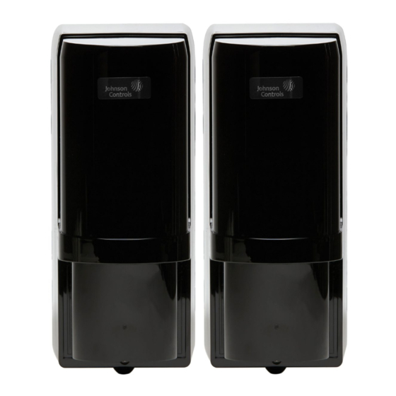
PowerG wireless photoelectric beam detector
• Battery life for transmitter is approximately three years, battery life for receiver is approximately
five years when using LSH20 (3.6V, 13Ah) batteries manufactured by SAFT
•
Battery saving function for wireless transmitter
•
Intermittent output function
•
4-channel beam frequency selector
•
International protection IP55
•
LED indicator for an easy alignment
•
D.Q. circuit (environmental disqualification)
•
Tamper
•
Beam interruption adjustment function
•
Outdoor detection range of 200 ft
Introduction
The PG9200AX is a PowerG wireless photoelectric beam detector that provides protection for outdoor perimeters.
Warning: Failure to follow the instructions provided with this indication and improper handling may cause death
or serious injury.
Caution: Failure to follow the instructions provided with this indication and improper handling may cause injury
and/or property damage.
Safety information
Warnings
•
Do not use the product for purposes other than the detection of moving objects such as people and vehicles.
•
Do not use the product to activate a shutter, etc., which may cause an accident.
•
Do not touch the unit base or power terminals of the product with wet hands. It may cause electric shock.
•
Do not touch when the product is wet. It may cause electric shock.
•
Never attempt to disassemble or repair the product. It may cause fire or damage to the devices.
•
Do not use batteries that have different levels of power remaining, that is, new and used batteries. Not observing
these guidelines may result in an explosion, leakage of electrolyte, emission of toxic gases, or other outcomes that
may be harmful to people and property.
•
When handling batteries, do not recharge, short circuit, crush, disassemble, exceed heat above 212°F (100°C),
incinerate, or expose contents to water. Do not solder directly to the cell. Not observing these guidelines may
result in fire, explosion, or severe burn hazard.
Cautions
•
Do not solder directly to the cell.
•
Do not pour water over the product with a bucket, hose, or similar. The water may enter, which may cause
damage to the devices.
•
Clean and check the product periodically for safe use. If any problem is found, do not attempt to use the product
as it is and have the product repaired by a professional engineer or electrician.
PG9200AX
Battery-operated photoelectric detector
Advertisement
Table of Contents

Subscribe to Our Youtube Channel
Related Manuals for Johnson Controls PowerG PG9200AX


Summary of Contents for Johnson Controls PowerG PG9200AX
- Page 1 PG9200AX Battery-operated photoelectric detector User manual Detector features • PowerG wireless photoelectric beam detector • Battery life for transmitter is approximately three years, battery life for receiver is approximately five years when using LSH20 (3.6V, 13Ah) batteries manufactured by SAFT •...
-
Page 2: Parts Identification
Parts identification Accessories Ordering detector batteries Specified batteries: Four LSH20 batteries manufactured by SAFT, two for the transmitter and two for the transceiver. For information about batteries, visit the following website and contact your local SAFT sales representative. See http://www.saftbatteries.com/battery-search/ls-lsh/. Enrolment The device is compatible with the following panels: •... - Page 3 1. Install batteries in the detector. 2. Turn the RF module power switch to the ON position. Refer to the control panel installation manual for the complete set of enrolment instructions and testing procedures. The enrolment procedure should begin automatically if the panel is already in enrolment mode. If the automatic enrolment procedure fails, refer to the control panel instructions and attempt manual enrolment of the device.
-
Page 4: Installation Advice
Installation Installation advice Callout Description Do not install the unit on an unstable surface Do not install the pole in location where it is not stable. Do not install the unit near trees or other objects that may block the beam. Do not install the receiver in a location that is exposed to direct sunlight. -
Page 5: Mounting On A Wall
In doing this installation, the maximum detection range shall be half of the original detection range. (This is to compensate the attenuation of beam by the corner of the cover.) Mounting on a wall 1. Loosen the back box lock screw. 2. - Page 6 To select between 4 separate beam frequencies, use the switch provided. • Make sure the receiver and transmitter that are facing each other are set to the same channel. • More than double stacked application is not possible. Note: Always switch the frequencies two channels apart when stacking units on top of one another. See the following example.
-
Page 7: Optical Alignment
e) Perimeter protection in a two-stack configuration Warning: • Do not attempt to install this product with any other photoelectric detector. It may cause the detector to fail or not respond to movements. • If the receiver of this product receives the beam from the wired photoelectric detector, it could be a factor of false alarm. - Page 8 Callout Component Horizontal alignment angle Vertical alignment angle 1. See 4-channel beam frequency selector and set the 4-channel beam frequency selector. 2. While looking through the view finder, adjust the horizontal and vertical angles so that the pairing detector is at the center of the sight. For fine alignment of the horizontal angle, turn the horizontal alignment dial.
-
Page 9: Beam Interruption Adjustment
4. After checking by the alarm indicator, make finer alignment with the voltmeter for both the transmitter and the receiver. Insert each probe of the voltmeter. Set the voltmeter range to 5 to 10 VDC. “good” 5. Continue the fine alignment until it reaches maximum monitor output over level. -
Page 10: Operation Check
Adjusting the output Setting the battery saving timer Even if the following events are occurred frequently, each output is generated with the intervals as below to save the battery drain. Function Setting Alarm output 1 output 2 minutes DQ output 1 output 2 minutes Low battery output 1 output 15 minutes... -
Page 11: Troubleshooting
When installing in a beam tower, make sure the tamper bushing is properly attached to main unit. Troubleshooting If the alarm indicator LED is off or blinking when the beam is interrupted, complete the following steps: 1. Align the optical axis again. 2. -
Page 12: Compliance With Standards
Operating ambient humidity 95% (Max.) Alignment angle ±90° Horizontal, ±5° Vertical Weight 56.4 oz (1600 g) (total weight of transmitter and receiver, excluding accessories) International protection IP55 Frequency 915 MHz Specifications and design are subject to change without prior notice. Compliance with standards USA: FCC- CFR 47 Part 15... -
Page 13: Limited Warranty
accordance with the instructions, may cause harmful interference to radio and television reception. However, there is no guarantee that interference will not occur in a particular installation. If this device does cause such interference, which can be verified by turning the device off and on, the user is encouraged to eliminate the interference by one or more of the following measures: –... -
Page 14: Description Of Other Rights And Limitations
Important Information: Changes or modifications not expressly approved by Digital Security Controls could void the user’s authority to operate this equipment. IMPORTANT - READ CAREFULLY: DSC Software purchased with or without Products and Components is copyrighted and is purchased under the following license terms: •... -
Page 15: Export Restrictions
(e) Software Product Transfer - You may transfer all of Your rights under this EULA only as part of a permanent sale or transfer of the HARDWARE, provided You retain no copies, You transfer all of the SOFTWARE PRODUCT (including all component parts, the media and printed materials, any upgrades and this EULA), and provided the recipient agrees to the terms of this EULA. - Page 16 Always ensure you obtain the latest version of the User Guide. Updated versions of this User Guide are available by contacting your distributor. © 2021 Johnson Controls. All rights reserved. JOHNSON CONTROLS, and DSC are trademarks and/or registered trademarks. Unauthorized use is strictly prohibited.
Need help?
Do you have a question about the PowerG PG9200AX and is the answer not in the manual?
Questions and answers