Table of Contents
Advertisement
Quick Links
User manual
Detector features
Battery saving function
•
IP65 waterproof rating, not evaluated by UL
•
4-channel beam frequency selector
•
Environmental disqualification circuit for configuring behavior in adverse weather conditions
•
Tamper function
•
•
Outdoor detection range of 350 ft
Introduction
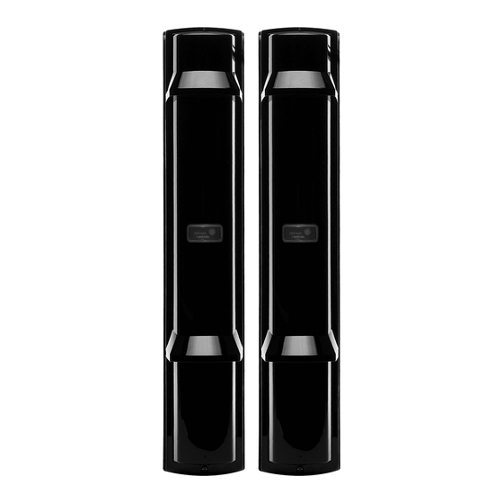
The PG9350SL is a PowerG wireless photoelectric beam detector that provides protection for outdoor perimeters.
Warning: Failure to follow the instructions provided with this device, or improper handling, may cause death or
serious injury.
Safety information
Warnings
•
Do not use the product for purposes other than the detection of moving objects such as people and vehicles.
•
Do not use the product for unintended purposes, such as activating a shutter, which may cause an accident.
Do not touch the product when it is wet or touch the unit base or power terminals of the product with wet hands. It
•
may cause electric shock.
•
Do not pour water over the product as it may cause damage.
Never attempt to disassemble or repair the product. It may cause fire or damage to the devices.
•
•
Do not use batteries that have different levels of power remaining, that is, new and used batteries. Not observing
these guidelines may result in an explosion, leakage of electrolyte, emission of toxic gases, or other outcomes that
may be harmful to people and property.
When handling batteries, do not recharge, short circuit, crush, disassemble, exceed heat above 100°C (212°F),
•
incinerate, or expose the contents to water. Do not solder directly to the cell. Not observing these guidelines may
result in fire, explosion, or severe burn hazard.
Clean and check the product periodically for safe use. If any problem is found, stop using the product, and have
•
the product repaired by a professional engineer or electrician.
Box contents
Transmitter and receiver modules
•
Product documentation
•
Hardware pack
•
PG9350SL
Wireless photoelectric beam detector
Advertisement
Table of Contents

Subscribe to Our Youtube Channel
Related Manuals for Johnson Controls PG9350SL


Summary of Contents for Johnson Controls PG9350SL
- Page 1 Outdoor detection range of 350 ft Introduction The PG9350SL is a PowerG wireless photoelectric beam detector that provides protection for outdoor perimeters. Warning: Failure to follow the instructions provided with this device, or improper handling, may cause death or serious injury.
-
Page 2: Parts Identification
Accessories Figure 1. Accessories Parts identification Figure 2. Parts identification... -
Page 3: Ordering Detector Batteries
Ordering detector batteries The specified batteries for the device are four (4) LSH20 batteries manufactured by SAFT, two for the transmitter and two for the receiver. For information about batteries, visit the following website and contact your local SAFT sales https://www.saftbatteries.com/products-solutions/products/ls-lsh-lsp representative. -
Page 4: Disassembling The Device
Disassembling the device Disassemble the device before enrolling and mounting. 1. Loosen the cover lock screw with a screwdriver. Figure 3. Loosening the cover lock screw 2. Place a coin in the recess and twist slightly to unlock the cover. Figure 4. - Page 5 Figure 7. Removing the main unit Caution: Do not place the main unit where it is exposed to direct sunlight. Doing so may cause damage to the product. 6. Loosen the 5 screws from the back cover and remove the chassis from the back-box. Note: Complete the Disassembly process for both the transmitter and receiver before mounting the device.
- Page 6 Enrollment Compatible panels • PowerSeries NEO (v1.37 and higher) PowerSeries Pro (v1.31 and higher) • IQ2+ (v2.6.2 and higher) • • IQ Hub (v3.0.1 and higher) IQ4 (v4.0.1 and higher) • Enrolling the device The device begins the enrollment process when the PowerG module is powered on. The PowerG module is a card in the detector.
-
Page 7: Additional Guidelines
Mounting Figure 9. Mounting guidelines Do not mount the device on an unstable surface Do not mount the device on an unstable pole. Do not mount the device near trees or other objects that may block the beam. When mounting on a pole, the pole diameter size should be 34 mm - 48 mm (1.34 in - 1.89 in). -
Page 8: Mounting On A Wall
Mounting on a wall 1. Using a screwdriver or similar tool, break the six knockouts in the back-box. The knockout positions are marked WALL. Figure 12. Preparing the back-box for mounting 2. Mount the back-box to the wall with the 4x20 screws. If two detectors are installed, the distance between the upper and lower detector should be at least 20 mm (0.78 in.). - Page 9 3. Insert two batteries into the lower battery recess of the back-box and set the RF module switch to the ON position. Figure 14. Inserting the batteries 4. Pull the cable through the chassis and tighten the screws. Tighten the screws in this order: a.
- Page 10 5. Insert the lower part of the main unit and push down to fix it onto the chassis. Figure 16. Inserting the main unit 6. Turn the optical unit 90 degrees and tighten the screws on both sides. Figure 17. Adjusting the optical unit 7.
- Page 11 8. To close the cover, hook the cover onto the upper part of the chassis and push the lower part of the cover until it clicks into position. Figure 19. Attaching the cover 9. Fasten the cover lock screw. 10. Push the middle part of the cover to hide the orange label completely when in operation.
-
Page 12: Mounting On A Pole
Mounting on a pole 1. Using a screwdriver or similar tool, break the knockouts marked POLE(1) on the back-box. Figure 20. Preparing the back-box for mounting 2. Mount the back-box on the pole with the M4x30 screws. If installing two detectors vertically, the distance between the upper detector and lower detector should be at least 20 mm (0.78 in.). - Page 13 Mounting a second detector in the opposite direction on a pole 1. For the second detector, using a screwdriver or similar tool, break the knockouts marked POLE(2) on the back-box. Figure 23. Preparing the back-box for mounting 2. Mount the back-boxes on the pole with the M4x30 screws. Attach double-sided tapes to the pole mounting brackets to make it easier to mount the device using the brackets.
-
Page 14: Device Settings
Device settings Warning: Do not change the default settings apart from the Battery saving timer. See Battery saving timer for more information. Changing the default settings can cause the device to function incorrectly and increases the chance of failure or false alarms. Switch functions Figure 25. -
Page 15: Installation Examples
Installation examples a. Double stacked protection. Since Receiver B may receive the infrared beam from Transmitter A, select the frequencies as shown in the figure below. In the figure, the number in the square indicates the channel. Figure 27. Double stacked protection b. - Page 16 d. Perimeter protection. Figure 30. Perimeter protection e. Perimeter protection in a two-stack configuration. Figure 31. Perimeter protection in a two-stack configuration Warning: Do not attempt to install this product with any other photoelectric detector. It may cause the detector to fail or •...
-
Page 17: Optical Alignment
Optical alignment After mounting, perform an optical alignment to ensure the device functions reliably. Caution: Do not touch the lens during optical adjustment. Alignment angles Figure 32. Alignment angles Aligning the device 1. Perform a rough alignment of the horizontal angle. a. - Page 18 2. Look into the viewfinder and perform fine alignment of the horizontal and vertical angles using the alignment dials. Turn the small dial for horizontal alignment. Turn the large dial for vertical alignment. Figure 34. Performing a fine alignment Warning: Do not look through the viewfinder under strong light sources such as sunlight. 3.
-
Page 19: Testing The Device
Testing the Device After installation, complete the following steps to test the device is functioning correctly: 1. Ensure the Alarm indicator LED is off. If it is on when the beams are not blocked, perform the steps in the Optical alignment section again. 2. -
Page 20: Optional Settings
Optional settings Warning: Do not change the default settings. Changing the default settings can cause the device to function incorrectly and increases the chance of failure or false alarms. DIP Switch and Output settings Figure 37. Dip Switch and Output settings Adjusting the beam interruption time You can adjust the beam interruption time settings according for the detectors intended target using one of the four selector positions below. -
Page 21: Troubleshooting
Troubleshooting Problem Possible cause Corrective action LEDs are not Reversed battery polarity Check battery polarity Illuminated (transmitter or receiver) Low battery indicator Low battery power Replace batteries blinks even though the battery has been inserted (transmitter or receiver) Alarm does not output Reflection from the floor or Align beams away from the wall. - Page 22 Dimensions Figure 40. Dimensions...
-
Page 23: Specifications
Specifications GENERAL Maximum detection range: 100 m/350 ft. Detection method: Quad infrared beam interruption detection Selectable beam frequency: 4 channels Interruption time: Variable between 50, 100, 250, and 500 ms Power source: Recommend: 3.6 V, 13.0 Ah LSH20 lithium batteries manufactured by SAFT. Current draw: 745 μA Transmitter: 420 μA + Receiver: 325 μA (at 25°C, 3.6 VDC)* Battery life: Transmitter: Approximately 4 years. -
Page 24: Compliance With Standards
UL/ULC Notes Only model PG9350SL operating in the frequency band 912-919MHz is UL/ULC listed. The PG9350SL has been listed by UL for commercial and residential burglary applications and by ULC for residential burglary applications in accordance with the requirements in the Standards UL 639 and ULC-S306 for Intrusion Detection Units. -
Page 25: Limited Warranty
Les antennes utilisées pour ce produit ne doivent pas être situés ou exploités conjointement avec une autre antenne ou transmetteur. IC: 160A-PG9350SL The term IC before the radio certification number signifies that the Industry Canada technical specifications were met. - Page 26 • If the DSC software product (“SOFTWARE PRODUCT” or “SOFTWARE”) is intended to be accompanied by HARDWARE, and is NOT accompanied by new HARDWARE, You may not use, copy or install the SOFTWARE PRODUCT. The SOFTWARE PRODUCT includes computer software, and may include associated media, printed materials, and “online”...
- Page 27 3. COPYRIGHT All title and intellectual property rights in and to the SOFTWARE PRODUCT (including but not limited to any images, photographs, and text incorporated into the SOFTWARE PRODUCT), the accompanying printed materials, and any copies of the SOFTWARE PRODUCT, are owned by DSC or its suppliers. You may not copy the printed materials accompanying the SOFTWARE PRODUCT.
- Page 28 Always ensure you obtain the latest version of the User Guide. Updated versions of this User Guide are available by contacting your distributor. © 2021 Johnson Controls. All rights reserved. JOHNSON CONTROLS, and DSC are trademarks and/or registered trademarks. Unauthorized use is strictly prohibited.
Need help?
Do you have a question about the PG9350SL and is the answer not in the manual?
Questions and answers