Table of Contents
Advertisement
Quick Links
User manual
Detector features
•
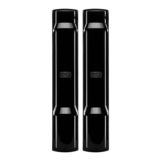
PowerG wireless photoelectric beam detector
•
Battery life for transmitter is approximately four years, battery life for receiver is approximately five
years when using LSH20 (3.6V, 13Ah) batteries manufactured by SAFT
•
Battery saving function
•
Intermittent output function
•
Quad high-power beams
•
Smart design with slim body
•
Vivid interior colour for optical alignment
•
IP65 waterproof structure
•
4-channel beam frequency selector
•
Viewfinder with 2X magnification
•
Beam interruption adjustment function
•
D.Q. circuit (environmental disqualification)
•
Tamper function
•
LED indicator for an easy alignment
•
Outdoor detection range of 350 ft
Introduction
The PG9350SL is a PowerG wireless photoelectric beam detector that provides protection for outdoor
perimeters.
Warning: Failure to follow the instructions provided with this device or improper handling may cause
death or serious injury.
Caution: Failure to follow the instructions provided with this device or improper handling may cause
injury and/or property damage.
Safety information
Warnings
•
Do not use the product for purposes other than the detection of moving objects such as people
and vehicles.
•
Do not use the product to activate a shutter, etc., which may cause an accident.
•
Do not touch the unit base or power terminals of the product with wet hands. It may cause electric
shock.
•
Do not touch when the product is wet. It may cause electric shock.
•
Never attempt to disassemble or repair the product. It may cause fire or damage to the devices.
•
Do not use batteries that have different levels of power remaining, that is, new and used batteries.
Not observing these guidelines may result in an explosion, leakage of electrolyte, emission of
toxic gases, or other outcomes that may be harmful to people and property.
•
When handling batteries, do not recharge, short circuit, crush, disassemble, exceed heat above
100°C (212°F), incinerate, or expose contents to water. Do not solder directly to the cell. Not
observing these guidelines may result in fire, explosion, or severe burn hazard.
Cautions
•
Do not solder directly to the cell.
•
Do not pour water over the product with a bucket, hose, or similar. The water may enter, which
may cause damage to the devices.
PG9350SL
Wireless photoelectric beam detector
Advertisement
Table of Contents

Related Manuals for Johnson Controls PG9350SL


Summary of Contents for Johnson Controls PG9350SL
- Page 1 • Outdoor detection range of 350 ft Introduction The PG9350SL is a PowerG wireless photoelectric beam detector that provides protection for outdoor perimeters. Warning: Failure to follow the instructions provided with this device or improper handling may cause death or serious injury.
-
Page 2: Box Contents
• Clean and check the product periodically for safe use. If any problem is found, do not attempt to use the product as it is and have the product repaired by a professional engineer or electrician. Installation advice Do not install the unit on an unstable surface Do not install the pole in location where it is not stable. -
Page 3: Ordering Detector Batteries
Accessories Ordering detector batteries Specified batteries: Four LSH20 batteries manufactured by SAFT, two for the transmitter and two for the transceiver. For information about batteries, visit the following website and contact your local SAFT sales representative. See http://www.saftbatteries.com/battery-search/ls-lsh/. Enrolment The device is compatible with the following panels: •... -
Page 4: Installation
Enrolling the device The device begins the enrolment process when the OPTEX RF module is powered on. The OPTEX RF module is a card in the detector. 1. Install batteries in the detector. 2. Turn the RF module power switch located on the interface board to the ON position. Refer to the control panel installation manual for the complete set of enrolment instructions and testing procedures. -
Page 5: Mounting On A Wall
3. Pull the cover from the back of the unit. 4. To remove the main unit from the chassis, turn the optical unit 90° and remove the screws from both sides. 5. Pull the upper part of the main unit forward and up to remove it. Caution: Do not place the main unit where it is exposed to direct sunlight. - Page 6 2. Mount the back box to the wall. If two detectors are installed, the distance between the upper and lower detector should be at least 20 mm. If mounting in a corner location, ensure the distance from the side wall is at least 1 m. Use a pitch of 83.5 mm when connecting to a gang electric box.
- Page 7 6. Turn the optical unit 90 degrees and tighten the screws on both sides. 7. Connect the cables and complete the setting and alignment 8. To close the cover, hook on the upper part of the chassis and push the lower part of the cover until it clicks into position.
-
Page 8: Mounting On A Pole
cover. Otherwise malfunction may occur due to the shift of the optical axis, resulting in the need of readjustment. 9. Fasten the cover lock screw. Notes: Ensure the cables do not get caught between the main unit and the cover. Push the middle part of the cover to hide the orange label completely when in operation. - Page 9 4. Insert the batteries into the back box. Note: Use of batteries other than recommended may shorten the battery life. Caution: Remove all batteries prior to replacing with new ones. If this is not followed, the low battery indicator LED will not reset and continue to blink. 5.
- Page 10 Installing two detectors in opposing directions 1. Using a screwdriver or similar tool, break the four knockouts on the back box. Note: Choose a different pair of knockouts. Pairs of the knockout positions are marked POLE(1) and POLE(2). 2. Fix the back box on the pole. Double-sided tapes attached to the pole mounting brackets make it easier to mount the unit with the combinations of the brackets.
- Page 11 Mounting the detector in the beam tower 1. Select a mounting pattern from the following options: Main unit Main unit plus Main unit plus chassis chassis plus back Mounting pattern Tamper position Caution: When using the tamper output, install the detector with the tamper shown above being pressed.
- Page 12 Mounting the detector separate from the back box in the beam tower 1. To remove the waterproof packing, remove the two screws fixing the waterproof packing. 2. Open the wiring guide on the back of the chassis using pliers. 3. Fix the back box and main unit.
-
Page 13: Functional Settings
Wiring This product is provided with wiring based on the assumption that N.C. wireless transmitters are used. Connect the cables from the back box (Yellow/Yellow-white, Green/Green-white, and Black/Black white) to the respective terminals on the wireless transmitters. Functional settings Receiver DIP switch 4 Channel beam frequency selector switch Battery saving timer switch Intermittent output function switch... - Page 14 c. Double stacked long distance protection. More than double stacked application is not possible. d. Perimeter protection. e. Perimeter protection in a two-stack configuration. Warning:...
-
Page 15: Optical Alignment
• Do not attempt to install this product with any other photoelectric detector. It may cause the detector to fail or not respond to movements. If the receiver of this product receives the beam from the wired photoelectric detector, it may cause false alarms. •... - Page 16 Warning: Do not look at strong light sources such as sunlight through the viewfinder. Caution: Do not touch the lens during optical adjustment. 3. After the alignment using the viewfinder, make adjustment with the voltmeter for more accurate optical alignment. Set the voltmeter range to 5 to 10 VDC.
- Page 17 Alarm output activation is limited to 2 minutes by a timer. Even if there are continuous alarm events, the alarm output operates only once in the timer period. Caution: Remove all batteries prior to replacing with new ones. If this is not followed, the low battery indicator LED will not reset and continue to blink.
-
Page 18: Troubleshooting
Checking the transmitter operation After installation is complete to check the operation. 1. Turn off the battery saving mode. 2. Make sure that the alarm indicator is off. If it is illuminated even when the beams are not blocked, make optical alignment again. 3. -
Page 19: Specifications
not activate. chassis and the back box are loose. The waterproof packing on Remove chassis from the back box is misplaced. back box and align the waterproof packing onto the chassis. Dimensions Specifications GENERAL Maximum detection range 100 m/350 ft. Maximum arrival distance 1000 m/3500 ft. -
Page 20: Compliance With Standards
OUTPUT Alarm output Form C-Solid State Switch: 3.6 VDC, 0.01 A Alarm period 2 sec (±1) (Nominal) D.Q output Form C-Solid State Switch: 3.6 VDC, 0.01 A (Receiver only) Low battery output N.C. (Solid State Switch): 3.6 VDC, 0.01 A Tamper output (cover, back box, main unit) N.C. -
Page 21: Fcc Compliance Statement
UL/ULC Notes Only model PG9350SL operating in the frequency band 912-919MHz is UL/ULC listed. The PG9350SL has been listed by UL for commercial and residential burglary applications and by ULC for residential burglary applications in accordance with the requirements in the Standards UL 639 and ULC-S306 for Intrusion Detection Units. -
Page 22: Limited Warranty
The term IC before the radio certification number signifies that the Industry Canada technical specifications were met. This Class B digital apparatus complies with Canadian ICES-003. This device complies with RSS-247 of Industry Canada. Operation is subject to the following two conditions: (1) this device may not cause interference, and (2) this device must accept any interference, including interference that may cause undesired operation of the device. -
Page 23: Description Of Other Rights And Limitations
a modification of any previous arrangement or contract. If You do not agree to the terms of this EULA, DSC is unwilling to license the SOFTWARE PRODUCT to You, and You have no right to use it. LICENSE The SOFTWARE PRODUCT is protected by copyright laws and international copyright treaties, as well as other intellectual property laws and treaties. -
Page 24: Export Restrictions
All title and intellectual property rights in and to the SOFTWARE PRODUCT (including but not limited to any images, photographs, and text incorporated into the SOFTWARE PRODUCT), the accompanying printed materials, and any copies of the SOFTWARE PRODUCT, are owned by DSC or its suppliers. - Page 25 Always ensure you obtain the latest version of the User Guide. Updated versions of this User Guide are available by contacting your distributor. © 2021 Johnson Controls. All rights reserved. JOHNSON CONTROLS, and DSC are trademarks and/or registered trademarks. Unauthorized use is strictly prohibited.
Need help?
Do you have a question about the PG9350SL and is the answer not in the manual?
Questions and answers