Table of Contents
Advertisement
Quick Links
Advertisement
Table of Contents

Related Manuals for Barco MDMG-5221


Summary of Contents for Barco MDMG-5221
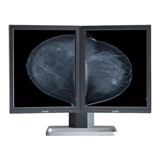
- Page 1 Mammo Tomosynthesis User Guide MDMG-5221 K5902035/07 07/12/2017...
- Page 2 Barco nv President Kennedypark 35, 8500 Kortrijk, Belgium Phone: +32 56.23.32.11 Fax: +32 56.26.22.62 Support: www.barco.com/esupport Visit us at the web: www.barco.com Printed in Belgium...
-
Page 3: Table Of Contents
Table of contents TABLE OF CONTENTS 1. Welcome! ..................3 About the product .................... . 3 What’s in the box. - Page 4 Table of contents 5.23 Grayscale conversion modes ................34 5.24 EDID timings..
-
Page 5: Welcome
To use the Mammo Tomosynthesis Display at its full capabilities you should make yourself familiar with these features and how to use them. Features with user interaction are explained in this guide. If you want more information on a specific feature refer to the Barco web site at http://www.barco.com/Healthcare contact the Barco Healthcare Division. - Page 6 • a film clip If you ordered a Barco display controller, it’s also in the box together with its accessories. A dedicated user guide is available on the system CD. Keep your original packaging. It is designed for this display and is the ideal protection during transport and storage.
-
Page 7: Parts, Controls And Connectors
2. Parts, controls and connectors 2. PARTS, CONTROLS AND CONNECTORS Display front view Overview 4 5 6 Image 2-1 Front view I-Luminate/Left key Right key Menu key Power on/off key Ambient light sensor Power LEDs Side downstream USB 2 & 3 K5902035 MAMMO TOMOSYNTHESIS 07/12/2017... -
Page 8: Display Rear View
2. Parts, controls and connectors Display rear view Connector compartment cover closed Image 2-2 Rear view cover closed Connector compartment cover Display release button Mounting anchor Connector compartment cover open Image 2-3 Rear view cover open 24 Vdc power input +5 Vdc, 0.5 A power output Display Port video input DVI video input... -
Page 9: Dual Tilt & Swivel Foot
2. Parts, controls and connectors The Ethernet connection is used for maintenance purposes and is not supported for user application. Dual tilt & swivel foot Overview Image 2-4 Dual tilt and swivel foot Left & right arm cover Cable cover Foot lock clip (behind cable cover) Display positioning sliders Accessories... - Page 10 2. Parts, controls and connectors Keyboard light Image 2-6 Keyboard light The keyboard light can be mounted under the display to provide a workspace light that is not interfering with the display image. K5902035 MAMMO TOMOSYNTHESIS 07/12/2017...
-
Page 11: Display Installation
Prior to installing your Mammo Tomosynthesis and connecting all necessary cables, make sure to have a suitable display controller physically installed in your computer. If you are using a Barco display controller, please consult the user guide delivered with it to do this. -
Page 12: Vesa-Mount Installation
3. Display installation 7. Pull out the foot lock clip. 8. Retain the clip for possible further transportations. 9. Now that the height-positioning is unlocked, you can adjust the position of the displays. Note: When both displays are not correctly aligned, minor corrections are possible in relative height and relative angle, by loosening and tightening the opposite pairs of allen screws (opposite sides or opposite diagonals) of the positioning sliders. -
Page 13: Connecting The Signal Cables
3. Display installation 2. Attach the display firmly to the VESA mounting bracket with 4 screws M4 x 10 mm. You should mount the display in portrait position. Landscape position is not supported. Connecting the signal cables AUTION Only connect one of the two video links. Connecting both inputs simultane- ously will result in driver errors. - Page 14 3. Display installation 3. Connect the DVI or DP of the display controller to the DVI or DP connector of the display. K5902035 MAMMO TOMOSYNTHESIS 07/12/2017...
- Page 15 3. Display installation Warning:Be aware that the DP connector is equipped with a cable latch, locking the connector to the display. To unplug the connector, press the button on the connector during removal. 4. If you want to make use of the display’s USB downstream connectors, connect a PC USB downstream connector to the display’s USB upstream connector.
-
Page 16: Routing The Cables
3. Display installation Routing the cables To route the cables If the display is mounted on the system dual tilt & swivel foot, cables are best routed behind the arms and through the cable channel in the foot shaft, as shown in the pictures below. K5902035 MAMMO TOMOSYNTHESIS 07/12/2017... -
Page 17: Positioning The Displays Angled
3. Display installation Positioning the displays angled To position the displays 1. Remove the arm covers. 2. Loosen the allen screws of both the left and right positioning slider. 3. Slide both displays at maximum distance from one another, being careful not to slide a display off the arm. - Page 18 3. Display installation FRONT 3. Hook the rear part of the white plastic clip in the display bezel gap. 4. Push firmly against the front part of the white plastic clip so that the clip pops into the display bezel gap. 5.
-
Page 19: First Time Starting Up
Your Mammo Tomosynthesis will be running in a basic video mode at a default refresh rate when first time starting up. If you are using a Barco display controller, please con- sult the user guide delivered with it to install the drivers, software and documentation. - Page 20 3. Display installation K5902035 MAMMO TOMOSYNTHESIS 07/12/2017...
-
Page 21: Daily Operation
LCD displays use technology based on pixels. As a normal tolerance in the manufacturing of the LCD, a limited number of these pixels may remain either dark or permanently lit, without affecting the diagnostic performance of the product. To ensure optimal product quality, Barco applies strict selection criteria for its LCD panels. -
Page 22: Key Indicator Lights
The ’MediCal QAWeb’ system offers online service for high-grade Quality Assurance, providing maximum diagnostic confidence and uptime. Barco recommends to install MediCal QAWeb Agent and apply the default QAWeb policy at least. This policy includes calibration on regular intervals. Connecting to MediCal QAWeb Server offers even more possibilities. -
Page 23: I-Luminate
4. Daily operation When the display is switched on, the power LED is blue. When the display is in stand-by mode, the power LED is orange. The power LED can be disabled in the OSD menus. Please refer to "Power status indi- cator light", page 24 for detailed instructions on how to do this. -
Page 24: Bringing Up The Osd Menus
4. Daily operation Bringing up the OSD menus How to bring up the OSD menus The OSD menu allows you to configure different settings to make your Mammo Tomosynthesis fit your needs within your working environment. Also, you can retrieve general information about your display and its current configuration settings through the OSD menu. -
Page 25: Advanced Operation
5. Advanced operation 5. ADVANCED OPERATION OSD menu position About the OSD menu position By default, the OSD menu comes up in the bottom center position of the screen. This position can be modified however. There’s choice from a number of predefined positions. To change the position of the OSD menu: 1. -
Page 26: Power Status Indicator Light
5. Advanced operation Power status indicator light About the power status indicator light By default, when the display is switched on, the power status indicator light is dimmed. This behavior can be changed so that the power status indicator light will be blue when the display is switched on. When the display is in stand-by mode, the power status indicator light will always turn orange, even when the power status indicator light is disabled. -
Page 27: Ethernet Over Usb
By enabling the Ethernet over USB, you allow the internal Mammo Tomosynthesis processor to commu- nicate directly over USB with the connected PC. Enabling the Ethernet over USB is only recommended when you are using a non-Barco display controller. If you are using a Barco display controller, this communication will automatically be done over the connected video cable(s). -
Page 28: Dpms Mode
By default, DPMS mode is enabled on your display, but it also needs to be activated on your workstation. To do this, go to the “Power options properties” window of your workstation. Barco recommends setting DPMS activation after 20 minutes of non-usage. When DPMS mode is enabled on your display, an additional OSD power saving function becomes available: hibernate. -
Page 29: I-Luminate Default Mode
5. Advanced operation 5.11 I-Luminate default mode About the I-Luminate default mode The I-Luminate mode defines the default activated mode during the I-Luminate boost. This mode can be: Screen The boost mode is applied on the screen display. Film (large or small) Film (large or small): the boost mode activates a high illuminated rectangle on top of the screen, simulating a light box for use with radiological film. -
Page 30: Viewing Modes
5. Advanced operation 5.14 Viewing modes About viewing modes The Mammo Tomosynthesis can be used in two viewing modes: Diagnostic This mode provides the full calibrated luminance and is intended for using the display for diagnostic purposes. Text In this mode, the luminance is reduced to approximately half of the luminance. -
Page 31: Ambient Light Compensation (Alc)
In short, the DICOM display function results in more visible grayscales in the images. Barco recommends selecting the DICOM display function for most medical viewing applications. User This display function will be automatically selected when display functions are defined by MediCal... -
Page 32: Continuous Alc
5. Advanced operation The American Association of Physicists in Medicine (AAPM) composed a list of pre-defined reading rooms. Each of these reading rooms are defined by following parameters: • the maximum light allowed in this type of room • the preset ambient light correction value for this reading room These parameters are stored in your display and determine the preset ambient light correction value to take into account to recalculate the DICOM display function when Ambient Light Compensation (ALC) is enabled. -
Page 33: Embedded Qa
Embedded QA is not a replacement for the Barco MediCal QAWeb solution. Although Embedded QA is a reliable option to perform a simple calibration or compliance test, Barco still highly recommends MediCal QAWeb as the solution of choice for calibration and QA. Medical QAWeb brings many benefits such as centralized asset management, the ability to schedule tasks, remote man-... -
Page 34: Dicom Compliance Check
5. Advanced operation No calibration executed yet. DICOM Calibration Status No other information is visible Calibration executed. When the calibration is executed, the following extra information is shown: Backlight runtime elapsed since latest calibration, display function, ambient light compensation, reading room. Current DICOM Settings Display function Shows the current display... -
Page 35: Dicom Error Threshold
5. Advanced operation 2. Navigate to the Configuration > Calibration > Embedded QA menu. 3. Enter the DICOM preferences submenu. 4. Select reset DICOM calibration to restore the original (not corrected) DICOM curve. 5.19.6 DICOM error threshold About DICOM error threshold The threshold to define the DICOM compliance can be modified in steps of 5% starting from 5 to 30%. -
Page 36: Video Encoding Modes
HDR1). This mode is usually used on color displays. Dual 10 (only with Barco display controller) Dual 10 is a Barco specific 10-bit video encoding mode which is usually used on grayscale displays and which allows full refresh rate. -
Page 37: Edid Timings
5. Advanced operation No Conversion Use Red Channel This mode is intended for grayscale displays where gray is sent over the red channel. Use Green Channel This mode is intended for grayscale displays where gray is sent over the green channel. Use Blue Channel This mode is intended for grayscale displays where gray is sent over the blue channel. -
Page 38: Display Status
5. Advanced operation To retrieve info about your display: 1. Bring up the OSD main menu. 2. Navigate to the About this Display menu to make the information visible on the screen. 5.26 Display status About display status The Status submenu of the OSD menu provides info on the current status of your display (runtimes, tem- peratures, etc.), the status of the connected image sources (video encoding mode, timings, etc.), the current calibration status of your display (display function, luminance, ALC, etc.) and the status about activated connections. -
Page 39: Cleaning Your Display
6. Cleaning your display 6. CLEANING YOUR DISPLAY Cleaning instructions To clean the display Clean the display using a sponge, cleaning cloth or soft tissue, lightly moistened with a recognized clean- ing product for medical equipment. Read and follow all label instructions on the cleaning product. In case of doubt about a certain cleaning product, use plain water. - Page 40 6. Cleaning your display K5902035 MAMMO TOMOSYNTHESIS 07/12/2017...
-
Page 41: Important Information
7. Important information 7. IMPORTANT INFORMATION Safety information General recommendations Read the safety and operating instructions before operating the device. Retain safety and operating instructions for future reference. Adhere to all warnings on the device and in the operating instructions manual. Follow all instructions for operation and use. -
Page 42: Environmental Information
7. Important information To fully disengage the power to the device, please disconnect the power cord from the AC inlet. Power cords: • Utilize a UL-listed detachable power cord, 3-wire, type SJ or equivalent, 18 AWG min., rated 250 V min., provided with a hospital-grade type plug 5-15P configuration for 120V application, or 6-15P for 240V application. - Page 43 (Also called RoHS of Chinese Mainland), the table below lists the names and contents of toxic and/or hazardous substances that Barco’s product may contain. The RoHS of Chinese Mainland is included in the MCV standard of the Ministry of Information Industry of China, in the section “Limit Requirements of toxic substances in Electronic Information Products”.
-
Page 44: Regulatory Compliance Information
“Electronic Information Products Pollution Control Labeling Standard” of Chinese Mainland, marked with the Environmental Friendly Use Period (EFUP) logo. The number inside the EFUP logo that Barco uses (please refer to the photo) is based on the “Standard of Electronic Information Products Environmental Friendly Use Period”... -
Page 45: Emc Notice
7. Important information CAUTION: Federal law restricts this device to sale by or on the order of a physician. (Details & exemptions are in the Code of Federal Regulations Title 21, 801 Part D) FCC class B This device complies with Part 15 of the FCC Rules. Operation is subject to the following two conditions: (1) this device may not cause harmful interference, and (2) this device must accept any interference re- ceived, including interference that may cause undesired operation. - Page 46 7. Important information This Mammo Tomosynthesis complies with appropriate medical EMC standards on emissions to, and interference from surrounding equipment. Operation is subject to the following two conditions: (1) this device may not cause harmful interference, and (2) this device must accept any interference received, including interference that may cause undesired operation.
- Page 47 7. Important information Immunity test Electromagnetic IEC 60601 Compliance level environment – Test levels guidance Electrostatic discharge ± 6kV contact ± 6kV contact Floors should be wood, (ESD) concrete or ceramic tile. ± 8kV air ± 8kV air If floors are covered with IEC 61000-4-2 synthetic material, the relative humidity should...
- Page 48 7. Important information Immunity test Electromagnetic IEC 60601 Compliance level environment – Test levels guidance d = 2.3√P 800 MHz to 2.5 Where P is the maximum output power rating of the transmitter in watts (W) according to the transmitter manufacturer and d is the recommended separation distance in...
-
Page 49: Explanation Of Symbols
7. Important information Rated maximum output Separation distance according to frequency of transmitter power of transmitter 150kHz to 80MHz 80MHz to 800MHz 800MHz to 2.5GHz d=1.2√P d=1.2√P d=2.3√P 0.01 0.12 0.12 0.23 0.38 0.38 0.73 At 80 MHz and 800 MHz, the separation distance for the higher frequency range applies. These guidelines may not apply in all situations. - Page 50 7. Important information Indicates the device is approved according to the CCC regulations Indicates the device is approved according to the VCCI regulations Indicates the device is approved according to the KC regulations Indicates the device is approved according to the BSMI regulations Indicates the device is approved according to the PSE regulations Indicates the USB connectors on the device Indicates the DisplayPort connectors on the device...
-
Page 51: Legal Disclaimer
Barco software products are the property of Barco. They are distributed under copyright by Barco N.V. or Barco, Inc., for use only under the specific terms of a software license agreement between Barco N.V. or Barco Inc. and the licensee. No other use, duplication, or disclosure of a Barco software product, in any form, is authorized. - Page 52 7. Important information Active screen size (diagonal) 540.9 mm (21.3”) Active screen size (H x V) 377,9 mm x 422,4 mm (14.9” x 16.6”) Aspect ratio (H:V) Resolution 5MP (2048 x 2560) Pixel pitch 0.165 mm Color imaging Gray imaging Number of grayscales (LUT 1024 gray levels (10/12) in/LUT out)
-
Page 53: Open Source License Information
Open source license usage This product contains software components released under an Open Source license. A copy of the source code is available on request by contacting your Barco customer support representative. EACH SEPARATE OPEN SOURCE SOFTWARE COMPONENT AND ANY RELATED DOCUMENTA- TION ARE PROVIDED "AS IS"... - Page 54 You acknowledge living up to the conditions of each separate Open Source Software license. A list of the Open Source Software components used is available in the applicable EULA, through the (customer section of the) Barco website or through other (online) means. K5902035 MAMMO TOMOSYNTHESIS 07/12/2017...
Need help?
Do you have a question about the MDMG-5221 and is the answer not in the manual?
Questions and answers