
Subscribe to Our Youtube Channel
Related Manuals for Vivint Element CT200

Summary of Contents for Vivint Element CT200
- Page 1 VIVINT ELEMENT THERMOSTAT USER GUIDE COMMUNICATING TOUCH SCREEN THERMOSTAT RTCOA logo sheet 7aug07...
-
Page 2: Table Of Contents
CT200 INSTALLATION GUIDE Table Of Contents Getting Started . . . . . . . . . . . . . . . . . . Interior View Installation Location Wiring . -
Page 3: Getting Started
Getting Started Radio Thermostat... - Page 4 Vivint Element CT200 Installation Guide Getting Started Tools Needed Small Phillips screwdriver Drill with ¼" bit (6 mm) CAUTION To avoid electrical shock and to prevent damage to the furnace, air condi- tioner, and thermostat, disconnect the power supply before installing or servicing the thermostat or any part of the system .
-
Page 5: Interior View
Vivint Element CT200 Installation Guide Getting Started Interior View Unit Back and Mounting Plate Wire terminals Up Button Unit Front Screen Side Button Down Button Bottom Edge Light... -
Page 6: Installation Location
Vivint Element CT200 Installation Guide Getting Started Installation Location To avoid having to move your wiring to a new location, mount the thermostat in place of the old thermostat . • Install the thermostat on an inside wall of an often-used room, about 5 ft. - Page 7 Wiring Radio Thermostat...
-
Page 8: Wiring
Vivint Element CT200 Installation Guide Wiring Preperation CAUTION • Read instructions carefully before removing any wiring from an existing thermostat . • Label all wires before disconnecting them form the existing thermostat . 1. Switch off electricity to the heating and cooling systems. This can be done at the circuit breaker . -
Page 9: Mounting Plate
Vivint Element CT200 Installation Guide Wiring Attaching the Mounting Plate to the wall 1 . Carefully pull the labeled wires through the center hole in the mounting plate . 2 . Position thermostat for best appearance to cover the hole in the wall . -
Page 10: Prepare Wires
Vivint Element CT200 Installation Guide Prepare Wires Wiring Make sure your wires are labeled. If necessary, find the “other end” connection for each wire on your heating or air conditioning equipment and note the label there . 1 . Fan out wires so that they are aligned with their terminals . -
Page 11: Connecting Wires
Vivint Element CT200 Installation Guide Connecting Your Wires Wiring Reference the Detailed Wire Diagram on page 23 to identify your wiring diagram and set-up information . If necessary, contact customer support for help . 1 . Connect a labeled wire only to a matching lettered terminal . -
Page 12: Power Supply
Vivint Element CT200 Installation Guide Wiring Power Supply While the thermostat can run without batteries on C-wire power, you should install batteries as well to provide power to the unit during outages . See the Thermostat Battery Cautions . 1 . Install four (4) AA alkaline batteries following the marked polarity in the battery compartments. - Page 13 Vivint Element CT200 Installation Guide Wiring THERMOSTAT BATTERY CAUTIONS • Always use new Alkaline batteries . • Do not use rechargeable batteries of any type . They will not operate the thermostat properly and may lead to damage . •...
-
Page 14: Setup
Setup Vivint Element CT200 User Guide... -
Page 15: Connecting To A Z-Wave Network
Connecting the Thermostat to a Z-Wave Network ® The Vivint Element Thermostat is a Z-Wave® compliant thermostat . It has an onboard radio that can be connected to an existing Z-Wave® network . This device can be used on a network with products from different vendors. -
Page 16: Z-Wave And Thermostat Programs
Vivint Element CT200 Installation Guide Setup Z-Wave and Power Supply The thermostat’s node type is fixed when it connects to the Z-Wave network; if the C-Wire is not connected and is only battery-powered when connecting to the network, the thermostat will remain a frequent listening routing slave (FLiRS) node until it is removed from the network . - Page 17 Vivint Element CT200 Installation Guide Setup SETTINGS Units Humidity Display Info Installer Navigating the Vivint Element Screens • Use the UP and DOWN buttons to move the cursor on the screen . • Use the SIDE button to make a selection or scroll through options .
-
Page 18: Select Hvac & Heat Types
Vivint Element CT200 Installation Guide Setup Selecting Heat Pump Settings Selecting HVAC & Heat Types 1 . From the Thermostat's Home 1 . From the Thermostat’s Home screen, press and hold the screen, press and hold the SIDE button for 3 seconds . - Page 19 Vivint Element CT200 Installation Guide Setup Selecting Cooling Type Selecting Humidity Settings 1 . From the Thermostat’s Home 1 . From the Thermostat’s Home screen, press and hold the screen, press and hold the SIDE button for 3 seconds . The SIDE button for 3 seconds .
-
Page 20: Test Installation
Vivint Element CT200 Installation Guide Setup Test Installation If you have a heat pump, leave the Thermostat in Off mode for 4 (four) minutes before checking Cool . Do not operate AC if the outside temp is below 65°F . - Page 21 Vivint Element CT200 Installation Guide Setup temperature, as well as the To Check Cool proper wires indicated as 1 . From the Thermostat’s Home being active . If the temperature screen, press and hold the appears to rise, or the wrong SIDE button for 3 seconds .
-
Page 22: Wiring Diagrams
Wiring Diagrams Vivint Element CT200 User Guide... -
Page 23: Detailed Wire Diagram
Vivint Element CT200 Installation Guide Wiring Diagrams Detailed Wiring Diagrams 3 Wire Heat 4 Wire Heat 5 Wire Heat/Cool 6 Wire Heat/Cool WIRES WIRES WIRES WIRES C W R C W R G C W Y R G C W Y RH RC G... -
Page 24: Step By Step Wiring Diagrams
Vivint Element CT200 Installation Guide Wiring Diagrams Step-By-Step Wiring Diagrams 3 Wire Heat GAS MILLIVOLT or HVAC SYSTEM 24VAC System POWER 1 . Connect the R (or RH) wire to the RH terminal . This connects the heat power . - Page 25 Vivint Element CT200 Installation Guide Wiring Diagrams 6 Wire Heat/Cool HVAC SYSTEM 1 . Connect the W wire to the W POWER terminal . This connects the heat . 2 . Connect the Y wire to the Y terminal . This connects to the...
- Page 26 Vivint Element CT200 Installation Guide Wiring Diagrams 4 Wire Heat Pump (heat/cool) HVAC SYSTEM without Auxiliary Heat 1 . Connect the O wire to the O POWER terminal or the B wire to the B terminal . This connects the change-over valve .
- Page 27 Vivint Element CT200 Installation Guide Wiring Diagrams Accessory Wiring Zoned Hot Water Heat For Solenoid or Motor valves, SOLENOID VALVE MOTOR VALVE connect the wires based on the CT102 CT102 diagrams to the correct terminal on the CT200 . When controlling a...
-
Page 28: Wire Reference Table
Vivint Element CT200 Installation Guide Wiring Diagrams Wire Reference Table Possible What They Control Wires R or V or VR RH and RC Single power for HEAT and COOL RH or 4 RH Power for HEAT (RH not connected to RC jumper clip... - Page 29 Vivint Element CT200 Installation Guide Wiring Diagrams Lennox Heat Pump V or VR or R RH Power for HEAT M or Y Y COOL control Y or W or W2 W2 2nd stage HEAT F or G G Fan control...
- Page 30 CT200 OPERATION GUIDE Product Overview Exterior View Screens Home Screen Outside Temp Screen Menu Screen Settings Screen Compressor Protection Settings Units Humidity Display Info Installer Equipment Comfort Calibration Cycling Staging Network Link Reset Testing Reset Restart Reset Other Device Information Low Battery Warning Network Disconnected...
- Page 31 Product Overview Radio Thermostat...
- Page 32 Vivint Element CT200 Operation Guide Product Overview Exterior View SETTINGS Units Humidity Display Info Installer Screens Navigating the Vivint Element screens • Use the UP and DOWN buttons to move the cursor on the screen . • Use the SIDE button to make a selection or scroll through options .
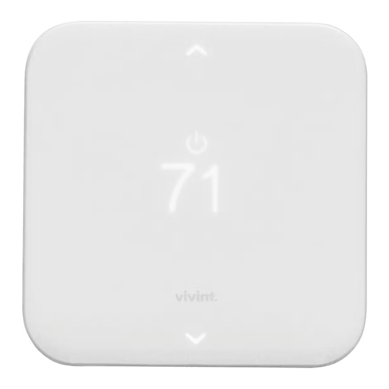
- Page 33 Vivint Element CT200 Operation Guide Product Overview Home Screen Mode Target Temp Room Temp This is the default screen on the Thermostat . Anytime the unit wakes from sleep (or senses you approaching, if the sensor is enabled), the screen lights up and displays the system’s mode (top), the target temperature (center), and the current room temperature (bottom) .
- Page 34 Vivint Element CT200 Operation Guide Product Overview Outside Temp Screen This screen displays the outside temperature and inside humidity (in %), and lets you put the system OUTSIDE TEMPERATURE into Vacation mode . 60° To see this screen, press the SIDE...
- Page 35 Vivint Element CT200 Operation Guide Product Overview Z-Wave and Thermostat Programs The Thermostat must be connected to a Z-Wave network in order to operate . Use your Z-Wave application to adjust the heating and cool- ing programs that the Thermostat uses to run your system . You can...
- Page 36 Customization Vivint Element CT200 User Guide...
- Page 37 Vivint Element CT200 Operation Guide Customization The Settings screen provides access to many features and settings of the Thermostat . Features you can control on the Settings screen are ºF / ºC display, humidity targets, display behavior, information about the Thermostat, and installer settings . The following pages provide detailed information about each of these settings .
- Page 38 Vivint Element CT200 Operation Guide Customization Display The Thermostat display can operate in one of two modes: Approach or Button Tap . Approach means that the device’s display will automatically turn DISPLAY ON: on when it senses you approach Approach Button Tap within 4 (four) feet of the unit .
- Page 39 Vivint Element CT200 Operation Guide Customization 1 . From the Home screen, press and hold the SIDE button for three (3) seconds . 2 . Press DOWN to highlight Info, then press the SIDE button . Information about the Thermostat displays .
- Page 40 Vivint Element CT200 Operation Guide Installer: Comfort Cont . Customization STAGING: Used for multiple stage systems only . Staging is the number of degrees between the room temperature and the target temperature at which the next stage in multi- stage systems will engage to bring the room temperature back to the target .
- Page 41 Vivint Element CT200 Operation Guide Customization STAGING 1 . From the Home screen, press and hold the SIDE button for three (3) seconds . 2 . Press DOWN to highlight START STAGE Installer, then press the SIDE 2 WHENEVER button .
- Page 42 Vivint Element CT200 Operation Guide Installer: Network/Reset Cont . Customization 5 . Highlight Link, then press the SIDE button . The unit attempts to connect to a local Z-Wave Network . RESET The Network>Reset resets the Thermostat's radio to unlink it from its linked Z-Wave Controller .
- Page 43 Vivint Element CT200 Operation Guide Customization Reset The Reset menu enables you to restart the Thermostat, as well as to reset the device to factory defaults . RESTART 1 . From the Home screen, press and hold the SIDE button for three (3) seconds .
- Page 44 Vivint Element CT200 Operation Guide Customization Other Device Information Low Battery Warning The Thermostat displays this screen when the batteries are running low on charge and should be replaced . This screen will only display once per day the first time the screen wakes.
- Page 45 Vivint Element CT200 Operation Guide FCC WARNING Changes or modifications to this unit not expressly approved by the party responsible for compliance could void the user’s authority to operate the equipment . NOTE: This equipment has been tested and found to comply with the limits for a Class B digital device, pursuant to Part 15 of the FCC Rules .
- Page 46 This device complies with Industry Canada’s licence-exempt RSSs. Operation is subject to the following two conditions: (1) This device may not cause interference; and (2) This device must accept any interference, including interference that may cause undesired operation of the device. Le présent appareil est conforme aux CNR d’Industrie Canada applicables aux appareils radio exempts de licence.
Need help?
Do you have a question about the Element CT200 and is the answer not in the manual?
Questions and answers