Table of Contents
Advertisement
Advertisement
Chapters
Table of Contents

Related Manuals for Vivint SmartHome ELEMENT

Summary of Contents for Vivint SmartHome ELEMENT
- Page 1 ELEMENT ™ THERMOSTAT USER GUIDE...
- Page 3 Climate controls, including temperature and humidity tracking, can be monitored and adjusted anywhere with the Vivint Smart Home app. When you’re at home you can just ask Alexa to adjust the temperature for hands-free control.
-
Page 4: Table Of Contents
Element INSTALLATION GUIDE Table of Contents Getting Started ..........................3 Unit View ................................5 Installation Location...........................6 Wiring ................................7 Mounting Plate ..............................9 Prepare Wires ..............................10 Connecting Wires ............................11 Power Supply ............................... 12 Wiring Diagrams ...........................26 Detailed Wire Diagram .......................... 27 Step By Step Wiring Diagrams ......................28 Wire Reference Table ..........................32 Setup ................................ -
Page 5: Getting Started
Getting Started... - Page 6 Vivint Element Installation Guide Getting Started Tools Needed Small Phillips screwdriver Level CAUTION CAUTION To avoid electrical shock and to prevent damage to the furnace and thermostat, disconnect the power supply before installing or servicing the thermostat or any part of the HVAC system.
- Page 7 Vivint Element Installation Guide Getting Started Unit Front Up Button Screen Side Button Bottom Down Button Edge Light Mounting Plate and Wire Terminals...
-
Page 8: Installation Location
Vivint Element Installation Guide Getting Started Installation Location To avoid having to move your wiring to a new location, mount the thermostat in place of the old thermostat. • Install the thermostat on an inside wall of an often-used room, about 5 ft. (1.5m) above the floor. -
Page 9: Wiring
Wiring... - Page 10 Vivint Element Installation Guide Wiring CAUTION CAUTION • Read instructions carefully before removing any wiring from an existing thermostat. • Label all wires before disconnecting them form the existing thermostat. • Test existing thermostat before turning off HVAC power to ensure HVAC system is working appropriately 1. Turn off power to the furnace or air handler (i.e. heating and cooling systems).
-
Page 11: Mounting Plate
Vivint Element Installation Guide Wiring Attaching the Mounting Plate to the Wall 1. Carefully pull the labeled wires through the center hole in the mounting plate. 2. Position thermostat for best appearance to cover the hole in the wall. 3. Mark first and drill a ¼ in. (6mm) hole at each screw location. 4. If you are mounting the Thermostat to sheet rock or if you are using the old mounting holes, use the plastic anchors provided. 5. Attach the Thermostat to the wall with the screws provided. -
Page 12: Prepare Wires
Vivint Element Installation Guide Wiring Prepare Wires Make sure your wires are labeled. If necessary, find the “other end” connection for each wire on your furnace or air handler (i.e.heating or air conditioning) equipment and note the label there. 1. Fan out wires so that they are aligned with the terminals. 2. Do not bunch wires in front of the mounting plate. Feed any slack back into the wall. If dual transformer (RH & RC wires), Do not allow wires to touch remove jumper. If single transformer each other or other parts on leave jumper on. the thermostat. Follow these guidelines for safe and secure wire connections: • Use at least 2.5 inches of wire for each of your connections to the Thermostat. • If you do not have enough wire, splice additional wire to allow enough slack. • Terminals accept wires from 16-22 AWG. • Remove 1/8 inch insulation from the tip of each wire. • Take care not to damage the labels for Jumper each wire. -
Page 13: Connecting Wires
Vivint Element Installation Guide Wiring Testing the Installation Connecting Your Wires Reference the Detailed Wire Diagrams on page 26 to identify your wiring diagram and set-up information. If necessary, contact customer support for help. 1. Connect a labeled wire only to a matching lettered terminal. 2. Insert the terminal labeled wire with corresponding terminal. (e.g. G wire goes to G terminal). 3. Make sure to insert the wire into the terminal as far as it will go. The wire should be secure and cannot be removed easily. Powering the Thermostat The Thermostat can be powered from 24VAC or by four AA alkaline batteries. 24VAC Powered Installation The thermostat can be powered from the HVAC system’s 24VAC transformer. This re- quires both the “R” and “C” wire to be connected to the thermostat. This is the preferred power option. The 24VAC “C” wire is the other side of the HVAC system’s transformer and can be found where the other thermostat wires connect at the wall or at the HVAC system. It is com- monly a blue wire. Do not use the common or ground side of the line voltage. - Page 14 Vivint Element Installation Guide Wiring Battery Powered Installation Install four (4) AA alkaline batteries following the marked polarity in the battery com- partments. Insert the battery negative end first against the spring, then push the posi- tive end in. Installing batteries Reconnecting Power to HVAC System With all the wires connected and the unit attached to the wall, it is time to turn the furnace and/or air handler power back on. Reconnect the power at the breaker you used to switch it off. The Thermostat will power-up in the Setup mode. Your Thermostat is not yet configured to operate your HVAC system. You must now connect your thermostat to a Z-Wave Network and configure the HVAC and Heat Source settings. Proceed to Setup Section...
- Page 15 Vivint Element Installation Guide Wiring CAUTION THERMOSTAT BATTERY CAUTIONS • Always use new Alkaline batteries. • Do not use rechargeable batteries of any type. They will not operate the thermostat properly and may lead to damage. • Do not mix old and new batteries.
-
Page 16: Wiring Diagrams
Wiring Diagrams... - Page 17 Vivint Element Installation Guide Diagrams Wiring Detailed Wiring Diagrams Diagram 1 Diagram 2 Diagram 3 Diagram 4 3 Wire Heat 4 Wire Heat 6 Wire Heat/Cool 5 Wire Heat/Cool C W R C W R G C W Y RH RC G...
-
Page 18: Step By Step Wiring Diagrams
Vivint Element Installation Guide Wiring Diagrams Step-By-Step Wiring Diagrams HVAC System DIAGRAM 1 R W C 2 Wire GAS MILLIVOLT or 24VAC System 1. Connect the R (or RH) wire to the RH terminal. Optional C Wire This connects the heat power. 2. Connect the W wire to the W terminal. This connects the heat. 3. If available, connect the C wire to the C terminal. Factory Installed 4. Go to “Connect Your Wires” on page 11. RC & RH... - Page 19 Vivint Element Installation Guide Wiring Diagrams HVAC System DIAGRAM 3 Y G R W C 4 Wire Heat/Cool 1. Connect the W wire to the W terminal. This Optional connects the heat. C Wire 2. Connect the Y wire to the Y terminal. This connects the cooling compressor. 3. Connect the RH or R wire to the RH terminal. This connects the power. Factory Installed 4. Connect the G wire to the G terminal. This RC & RH connects the fan. Jumper Thermostat 5. If available, connect the C wire to the C...
- Page 20 Vivint Element Installation Guide Wiring Diagrams DIAGRAM 5 Two-stage Heat & Two-Stage Cool HVAC System The Element can handle up to 2 stages of Y 2 Y G R W W 2 C HEAT and 2 stages of COOL. Optional 1. Connect the W and W2 wires to the W and C Wire W2 terminals. This connects the stages of HEAT. 2. Connect the Y and Y2 wires to the Y and Y2 terminals. This connects the stages of Factory COOL. Installed RC & RH 3. Connect the RH or R wire to the RH...
-
Page 21: Wire Reference Table
Vivint Element Installation Guide Wiring Diagrams DIAGRAM 7 Two-stage Heat Pump with Two-Stage Aux Heat The Element can handle up to 2 stages of Pump compression and 2 stages of AUX heat. Aux Heat 1 1. Connect O wire to the O terminal or the B Aux Heat 2 wire to the B terminal. This connects the HVAC System change-over valve. If you have both O and Y2 Y G R W W2 O/B C B, connect only the O wire to the O terminal and DO NOT connect B to B terminal (see Optional... - Page 22 Vivint Element Installation Guide Wiring Diagrams Wiring Reference Table Element Possible Wires What They Control Terminal R or V or VR RH and RC Single power for HEAT and COOL RH or 4 RH Power for HEAT (RH not connected to RC...
- Page 23 Vivint Element Installation Guide Wiring Diagrams Element Old Lennox Systems Terminal V or VR or R RH Power for HEAT Y COOL control Y or W or W2 W2 2nd stage HEAT F or G G Fan control R or O...
-
Page 24: Setup
Setup... - Page 25 Vivint Element Installation Guide Setup Setup The initial setup will take you through the following steps: 1. Connecting to the panel 2. Setting up humidity 3. Setting up heating 4. Setting up cooling 5. Selecting heat or cool mode The following pages describe in detail this setup process.
- Page 26 Vivint Element Installation Guide Setup Connecting the Thermostat to the Panel (Classic Inclusion) The Vivint Element Thermostat is a Z-Wave compliant thermostat. It can be ® operated in any Z-Wave network with other Z-Wave certified devices from other manufacturers. All main operated nodes within the network will act as repeaters regardless of vendor to increase reliability of the network if not battery operated. Below describes how to add to the Vivint panel. 1. Set your panel to add node mode to add the thermostat as a node on your network. 2. The Thermostat main screen shows a welcome message. Press the SIDE button to continue. 3. When your panel is ready to connect to the Thermostat, press the SIDE button to connect. This initiates the network connection process. The Thermostat’s screen says “Connecting.” • If the connection fails, the screen says, “Failed.” Press the SIDE button to try connecting again. 4. When the Thermostat has successfully joined a Z-Wave network from the panel, the screen displays the message “Next” . 5. Complete your setup on the VIVINT panel. 6. Press the SIDE button to continue.
- Page 27 Vivint Element Installation Guide Setup SmartStart Inclusion (Optional) SmartStart enabled products can be added into a Z-Wave network by scanning the Z-Wave QR Code present on the product with a controller providing SmartStart inclusion. No further action is required and the SmartStart product will be added automatically within 10 minutes of being switched on in the network vicinity. The SmartStart QR code can be found on the back of the product, side of the package, or also inserted as a sticker. The sticker contains the full DSK string. It’s important that if you plan to use DSK that you keep this label in a safe place you’ll remember. NOTE: The Vivint panel currently does not support SmartStart inclusion. SmartStart QR code on sticker SmartStart QR code on box SmartStart QR code on product...
-
Page 28: Set Up Hvac - Humidity
Vivint Element Installation Guide Setup: HVAC - Humidity Connecting to Panel Workflow (Classic Z-Wave Inclusion) START PRESS PANEL press press CONNECT SIDE SIDE button button FAIL Make selection RE-TRY WAIT with arrows and then press SKIP SIDE button FAILED press PASS SIDE button to advance... - Page 29 Vivint Element Installation Guide Setup Setting up Humidity 1. Press the UP/DOWN button until the type of humidity system you have is displayed: None, Humidifier or Dehumidifier. 2. Under Activate, press the UP/DOWN buttons until the method your humidity system uses is displayed: with Heating, with Cooling, or Independent. Press SIDE button. 3. Under Fan, press the UP/DOWN button until the fan option your humidity system uses is displayed: Active or Inactive. Press SIDE button. TYPE None...
- Page 30 Vivint Element Installation Guide Setup: HVAC - Humidity Setting Up Humidity Workflow SET UP press HUMIDITY SIDE button NEXT TYPE if None, Press SIDE button None press UP/DOWN button to select SET UP TYPE ACTIVATE HEATING press press press SIDE SIDE SIDE button button button with...
-
Page 31: Set Up Hvac - Heating
Vivint Element Installation Guide Setup: HVAC - Heating Setting up Heating 1. Press the UP/DOWN button until your heating type is displayed: None, Forced Air, Heat Pump or Radiant. 2. Under stages, press the UP/DOWN button until your system’s heating stage type is displayed. Stages are not available if Radiant heating type was selected. For Forced Air you’ll see 1, 2, or 3 stages. For Heat Pump you’ll see 1, 2, 1+1 Aux, 1+2 Aux, 2+1 Aux, or 2+2 Aux. 3 stages Forced Air or 2+2 Aux Heat Pump utilize the auxiliary terminal, therefore, if your using humidity control these options will not be available. Press SIDE button. 3. Under Fuel, press the SIDE button until your heating fuel is displayed: Natural Gas, Propane, Fuel Oil and Electric. For Heat Pump systems, this field is labeled Aux Fuel. Press SIDE button. Note: Auxiliary stages are only available if you select Heat Pump as the heating type. TYPE Forced Air... - Page 32 Vivint Element Installation Guide Setup: HVAC - Heating Setting Up Heating Workflow SET UP HEATING press SIDE button NEXT HP Type only FUEL O/B Wire TYPE STAGES press press press SIDE SIDE SIDE Natural button button button None Activated for Cool...
- Page 33 Vivint Element Installation Guide Setup: HVAC - Cooling Setting up Cooling 1. Under Type, press the UP/DOWN button until your Cooling type is displayed: None, Air Condition or Heat Pump. 2. Under Stages, press the UP/DOWN button until the number of stages your system uses is displayed: 1(single) or 2 (mutlistage). TYPE Condition...
- Page 34 Vivint Element Installation Guide Setup: HVAC - Cooling Setting Up Heating Workflow SET UP press COOLING SIDE button NEXT TYPE STAGES press make make SIDE selection selection button with arrows with arrows None and then and then press SIDE press SIDE DONE button button Use the UP/DOWN Use the UP/DOWN...
- Page 35 Vivint Element Installation Guide Setup: HVAC - Mode Selecting Mode To change mode, press the SIDE button. Use the UP/DOWN arrows to change the mode. OFF, HEAT, COOL, HEAT & COOL, E-HEAT. E-HEAT: For Heat Pump Systems with Aux Heat Stages. SELECT MODE At this point your setup is complete.
- Page 36 Vivint Element Installation Guide Setup: HVAC - Mode Selecting Mode Workflow Use DN press arrow to SIDE SELECT select mode HEAT & button MODE COOL Press SIDE button to select HEAT COOL OPTIONAL Only for Heat Pump Systems with Aux E-HEAT Heat...
- Page 37 Vivint Element Installation Guide Setup Testing the Installation After installation, operation can be tested. In the Settings menu, under the User Settings, is the Testing menu. There is a heating test and a cooling test. The heating and cooling tests run for up to 30 minutes. You can stop a test at any time by selecting the arrow and pressing the SIDE button. Use the UP and DOWN arrows to move the highlighted selection on the screen. Use the SIDE button to make a selection or advance through options. To Check Heating 6. Press the SIDE button to stop test. 7. Press the SIDE button again to exit 1. From the Thermostat’s Home back to TESTING menu. screen, press and hold the SIDE button until the Settings menu A test of a successfully functioning appears (approximately 3 seconds). heating system will show a rise in the temperature, as well as the proper 2. Highlight User, then press the SIDE wires indicated as being active. If the button. The User Settings menu temperature appears to drop, or the opens. wrong wires are indicated as being 3. Use the UP/DN arrows to select active, the test indicates a problem Testing. Press SIDE button. The with the Thermostat installation. Testing menu opens.
- Page 38 Vivint Element Installation Guide Setup Testing the Installation To Check Cooling 1. From the Thermostat’s Home screen, press and hold the SIDE button until the Settings menu appears (approximately 3 seconds). 2. Highlight USER, then press the SIDE button. The USER Settings menu opens. 3. Use UP/DN arrows to select Testing, then press the SIDE button. The Testing menu opens. 4. Use UP/DN arrows to select Cool, then press the SIDE button. The Cool Test menu opens. 5. Press the SIDE button to start test. The Thermostat screen displays the following: • COOL TIME: how long the test has been running in minutes and seconds COOL • ACTIVE: the wires the system is using 18:24 to communicate with the cooling system -2.6° (example: Y, G) STOP • CHANGE: the amount of temperature change caused during the test (example: -2 .6°)
-
Page 39: Z-Wave And Thermostat Programs
Z-Wave and Power Supply The thermostat’s node type is pre-determined when it connects to the Z-Wave network; if the C-Wire is not connected and is only battery-powered when connecting to the network, the thermostat will remain a frequent listening routing slave (FLiRS) node until it is removed from the network. When your thermostat is running on battery power, the Z-Wave radio will turn off to help conserve battery life. The Thermostat Z-Wave radio module supports Z-Wave beaming, which allows other devices in the network to wake up the Z-Wave module and accept commands and then go back to sleep. When your thermostat is running on C-Wire power, the Z-Wave radio will stay on and actively help route messages within the Z-Wave network. The thermostat’s node type is pre-determined when it connects to the Z-Wave network; if the C-Wire is present and powered when connecting to the network, the thermostat will remain an always-listening node until it is removed from the network. Z-Wave and Thermostat Programs You must connect the Thermostat to a Z-Wave network. This unit cannot operate without a network connection. When you are paired to a Z-Wave system, the Z-Wave application on your device controls your thermostat’s programs. You can still temporarily override settings on the thermostat itself, but otherwise you control it remotely. - Page 40 OPERATION GUIDE Element Product Overview ........................35 Home Screen ..............................36 Outside Temp Screen ..........................37 Menu Screen Settings Screen ......................38 Compressor Protection ........................39 Customization ..........................40 User Settings ..............................41 Units ................................... 41 Humidity ................................41 Display ................................42 Info ..................................42 Installer Settings ............................43 Equipment ..............................43 Calibration ..............................44 Cycling ................................43...
-
Page 41: Product Overview
Product Overview... -
Page 42: Navigating Screens
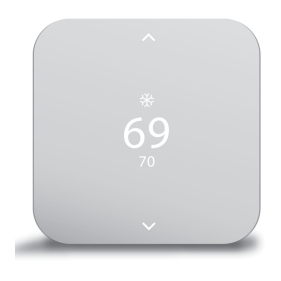
Vivint Element Operation Guide Product Overview For UP arrow press here Home Screen For SIDE button Mode press here Target Temp Room Temp For DOWN arrow Light Bar press here This is the default screen on the Thermostat. Anytime you press the front of the thermostat, the unit wakes from sleep (or senses you approaching, if utilizing C-wire and wake-on- approach is enabled), the screen lights up and displays the system’s mode (top), the target temperature (center), and the current room temperature (bottom). When in Heat mode, the light bar at the bottom of the unit glows orange. When in Cool mode, it glows blue. When the unit is off, the light bar does not glow. When the system is actively heating or cooling, the colored glow “breathes” when the display is on. • To temporarily change the target temperature, press up/down. The system will meet the target temperature until the next program period starts or you change the system mode. Navigating The Screens • Press the UP/DOWN arrows to move the cursor on the screen • Press the SIDE button to make a selection or scroll through options • To go back to a previous screen, press and hold the UP arrow at the top of the screen and press the SIDE button. • From the home screen, press the SIDE button to turn the system on. Press the SIDE... - Page 43 Vivint Element Operation Guide Product Overview Mode To change mode, when the home screen is displayed, press the SIDE button. Use the up/down arrows to change the mode. OFF, HEAT, COOL, HEAT & COOL, E-HEAT E-HEAT: For Het Pump Systems with Aux HEAT Heat ONLY To change the fan mode, when the home screen is displayed, press the SIDE button twice. Use the up/down arrows to change the fan mode. 15 min., 30 min., 60 min., ALWAYS ON, STOP Outside Temperature Screen To see the outside temperature, press and OUTSIDE HUMIDITY hold the SIDE button for 3 seconds. 94° To see the inside humidity, press the UP/DOWN arrows. 82°...
- Page 44 Vivint Element Operation Guide Product Overview Settings Screen USER This screen enables you to adjust the Units Thermostat’s settings, such as display units SETTINGS (°F or °C), target humidity levels, how the User display activates, see information about the USER Installer Thermostat, and adjust installation settings. Done Display To see this screen, from the Home screen, press and hold the SIDE button for six (6) seconds. USER Use UP/DOWN arrows to change selection. Press side button to select the settings Humidity menu circled. User Settings Installer Settings USER options include: options include: • Units • Equipment Info • Display • Network • Humidity (optional) • Calibrate...
-
Page 45: Compressor Protection
Vivint Element Operation Guide Product Overview Z-Wave and Thermostat Programs The Thermostat must be connected to a Z-Wave network in order to operate the device remotely through your panel or app. Use your Z-Wave application to adjust the heating and cooling programs that the Thermostat uses to run your system. You can temporarily override target temperatures and change system modes from the thermostat, but you must use the Z-Wave application to make permanent changes to programs. Compressor Protection The Thermostat has a minimum cycle time of five (5) minutes to protect your compressor from excessive wear from responding to thermostat changes. The Home screen shows the message “Cycle Delay”. The compressor will not come on until the five-minute delay is over. -
Page 46: Customization
Customization... -
Page 47: User Settings
Vivint Element Installation Guide Customization User Settings The Settings screen provides access to many features and settings of the Thermostat. Features you can control on the Settings screen are ºF / ºC display, humidity targets, display behavior, information about the Thermostat, and installer settings. The following pages provide detailed information about each of these settings. From the Home screen, press and hold the SIDE button for three (3) seconds to access the settings screen. Then use the UP/DN arrows to select the desired user setting. Then press the SIDE button. Units The Thermostat can display either Fahrenheit or Celsius temperature units. The Thermostat can display room Options: temperatures in a range from 28°F to UNITS UNITS 99°F (-2°C to 37°C) with increments of 0.5° (F or C). °F °C 1. Press DOWN to highlight Units, then press the SIDE button. 2. Using the UP or DOWN arrows, select an option, then press the SIDE button to confirm and return to USER settings. Display The Thermostat display can operate in one of two modes: Wake on Approach or Wake on Button Press. Options: Wake on Approach means that the device’s display will automatically turn... -
Page 48: Humidity
Vivint Element Installation Guide Customization Humidity Options: This screen is only available if your system HUMIDITY includes humidity controlling equipment. 1. Press DOWN to highlight Humidity, then Disable HUMIDITY press the SIDE button. 2. Using the UP or DOWN arrows, select Enable an option, then press the SIDE button to HUMIDITY confirm and return to USER settings. If enabled, set the humidity setpoint: 10-45%, default 40%. Info Information about the Thermostat device includes: POWER: The power supply the unit is Options: currently using (batteries, C-wire, and/or transformer). INFO BATTERY: How much battery power is HVAC TYPE currently left, if batteries are installed in Heat Pump Aux Heat the unit. INFO HVAC TYPE: The HVAC Type setting the... - Page 49 Vivint Element Installation Guide Customization Testing USER Testing options enable you to test the functionality of your heating and cooling equipment’s connection to Testing the Thermostat. For instructions on running these tests, see page 36 in the Installation Guide. TESTING TESTING press press SIDE SIDE Heat Cool button button HEAT COOL 0:00 0:00 press press SIDE SIDE 0.00° 0.00° button button START START COOL HEAT...
-
Page 50: Installer Settings
Vivint Element Installation Guide Customization Installer Settings Installer settings control the following Thermostat functions: EQUIPMENT: heating, cooling, humidity control, and fan behavior The Equipment settings menu is typically used during installation of the Thermostat. The options in this menu enable you to set the heating, cooling and humidity control. NETWORK: the Thermostat’s connection to a Z-Wave Network CALIBRATE: Offsets the unit’s temperature display CYCLING: This feature enables you to set the acceptable variance in temperature between the Thermostat’s setting and the current room temperature before the heating or cooling system will turn on. The Cycling range can be from 0.5 to 4.0F (.25 to 2C). For example, if Cycling is set to 2.0°F and the Thermostat is set to 70°F target temperature, the heat cycle will start when the room temperature drops to 68°F. Similarly, the cooling system will start when the room temperature increases to 72°F. The HVAC runs until the room reaches the target temperature, and then shuts off. STAGING: Used for multiple stage systems only. Staging is the number of degrees between the room temperature and the target temperature at which the next stage in multi-stage systems will engage to bring the room temperature back to the target. The default is 2°F. The programmable range is 2°F to 6°F (1°- 3°C). RESET: resetting the Thermostat’s settings to factory defaults. CAUTION WARNING Be sure to turn the thermostat operating mode to OFF before changing HVAC setup To get into Installer Settings, from the Home Screen, press and hold the SIDE button for three (3) seconds to access the SETTINGS menu. Use the UP/DN arrows to select the INSTALLER SETTINGS. Press the side button. Use the UP/DN arrows to select the desired installer setting. -
Page 51: Equipment
Vivint Element Installation Guide Customization Equipment From the Installer Setting menu, select Equipment and press the SIDE button. INSTALLER EQUIP. The Equipment menu will open and has the following menu items Equipment Heating • Humidity • Heating • Back • Cooling EQUIP. Use the UP/DOWN arrows to select the menu item. Cooling Heating EQUIP. Press SIDE button to select TYPE Humidity Use UP/DOWN buttons to select heating system type EQUIP. • None • Forced Air Back • Heat Pump • Radiant... - Page 52 Vivint Element Installation Guide Customization Cooling ACTIVATE Use UP/DOWN arrows to select Press SIDE button to select Cooling when Humidity control is active Setup • Independent (Humidity control TYPE turns on independent of Heating Use UP/DOWN arrows to select or Cooling operation) Cooling system type: • With Heating (If Humidifier type) • None only during Heating operation • Air Condition • With Cooling (If Dehumidifier type) only during cooling • Heat Pump operation Press SIDE button to select STAGES Use UP/DOWN arrows to select Use UP/DOWN arrows to select Fan action number of cooling stages: • Inactive (No Fan action when • 1 Humidity mode is on) • 2...
-
Page 53: Calibration
Vivint Element Installation Guide Customization Network Network settings enable you to connect NETWORK to a Z-Wave Network using Classic Inclusion, and to reset the Thermostat Connect to a Z-Wave Network, and to reset the INSTALLER network connection. Z-Wave Before starting this procedure, go to Network NETWORK your Vivint panel and prepare it for new devices. Once it is ready, connect the Disconnect Thermostat to the network. Z-Wave 1. Press DOWN arrow to highlight Network, then press the SIDE button. If the thermostat IS NOT connected to the Z-Wave Network, “Connect” will be displayed. Press the SIDE button to connect. If the thermostat IS connected to the Z-Wave Network, “Disconnect” will be displayed. Press the SIDE button to disconnect. Select “Back” to exit and return to INSTALLER menu. TEMP Offset by Calibration 0.0°... -
Page 54: Cycling
Vivint Element Installation Guide Customization Cycling CYCLING 1. Press the DOWN arrow to highlight Cycle when Cycling, then press the SIDE button. 1.0° The current cycling value displays. off target INSTALLER 2. Press UP or DOWN arrow to change CYCLING the value, then press the SIDE button Cycling Cycle when to confirm. 1.5° 3. Ranges are in .5 increments: from 3.0 off target to 1.0, default 1.0. CYCLING Cycle when 2.0° off target CYCLING Cycle when 2.5°... -
Page 55: Staging
Vivint Element Installation Guide Customization Staging STAGING Used for multiple stage systems only. Stage 2 Heat at Staging is the number of degrees between the room temperature and the target 2.5° INSTALLER temperature at which the next stage in multi- STAGING stage systems will engage to bring the room Staging Stage 2 temperature back to the target. The default Cool at is 2°F. The programmable range is 2°F to 6°F (1°- 3°C). 2.5° 1. Press DOWN arrow to highlight Staging, STAGING then press the SIDE button. The current Fast staging value displays. Recovery? 2. Press UP or DOWN arrow to change the value, then press the SIDE button to confirm. STAGING Fast 3. Ranges are in .5 increments: 2.5, 3.0, 3.5,... -
Page 56: Other Device Information
Vivint Element Installation Guide Customization Other Device Information Low Battery Warning The Thermostat displays this screen when the batteries are running low on charge and should be replaced. This screen will BATTERY only display once per day the first time the screen wakes. 1. Press the SIDE button to dismiss this warning. 2. Turn the thermostat mode to OFF (from heat or cool). 3. Replace the batteries. 4. Turn the thermostat mode back on to HEAT or COOL. Your settings will be retained and the thermostat will automatically reconnect to the Z-Wave Network. - Page 57 • Connect the equipment to an outlet on a circuit different from that to which the receiver is connected. • Consult the dealer or an experienced radio/TV technician for help. WARNING: Changes or modifications to this receiver not expressly approved by Vivint void the user’s authority to operate this equipment. RF Exposure info -- (manual) This equipment complies with FCC’s and IC’s RF radiation exposure limits set forth for an uncontrolled...
- Page 58 Z-Wave Specifications Supported Commands: • Battery Report • Device Reset Locally Notification • Sensor Multilevel Report • Thermostat Setpoint Report • Thermostat Mode Report V3 • Thermostat Fan Mode Report • Thermostat Fan State Report • Thermostat Operating State Report V2 • Notification Report V8 • Configuration Report Z-Wave Association • Group Number: 1 • Group Name: Lifeline • Max Nodes: 5 • Profile ID: 0x0001 • Endpoint: 0...
- Page 59 140-02345 02/10/20...
Need help?
Do you have a question about the SmartHome ELEMENT and is the answer not in the manual?
Questions and answers
How do you set the thermostat just to work without staging or cycling. just need it to work like a regular thermostat?
To set the Vivint SmartHome ELEMENT thermostat to operate like a regular thermostat without staging or cycling:
1. Disable Staging: Ensure the thermostat is not connected to a multi-stage system or set the staging value high enough so the second stage never activates. This way, only the primary heating or cooling runs.
2. Minimize Cycling: Set the cycling value to the smallest allowable variance (0.5°F). This reduces the delay between the room reaching the set temperature and the HVAC system turning on or off, making it behave like a standard thermostat.
This setup minimizes advanced features and makes the thermostat function in a basic, on/off manner based on the set temperature.
This answer is automatically generated
Your **** smart thermostat isn't working. Is there any way I can manually turn my furnace on so I don't **** freeze to death? Huh?
The Vivint SmartHome ELEMENT thermostat does not provide specific instructions for manually turning on the furnace. However, you can control the thermostat settings through the device itself, the Vivint Smart Home app, or voice commands with Alexa. To ensure the furnace operates correctly, make sure the thermostat is properly installed, connected to the Z-Wave network, and configured for your HVAC system. If the furnace does not turn on, check the power supply, wiring, and thermostat settings.
This answer is automatically generated
why is my air running all the time