TESTO 6383 Instruction Manual
Differential pressure transmitter
p2a software. parameterizing, adjusting and analyzing software
Hide thumbs
Also See for 6383:
- Instruction manual (140 pages) ,
- Instruction manual (76 pages) ,
- Instruction manual (64 pages)

Related Manuals for TESTO 6383


Summary of Contents for TESTO 6383
- Page 1 6383 · differential pressure transmitter P2A software · Parameterizing, adjusting and analyzing software Instruction manual...
-
Page 3: Safety And The Environment
Use only original spare parts from Testo. Any additional work must only be carried out by authorized personnel. Otherwise testo will not accept any responsibility for the proper functioning of the instrument after repair and for the validity of certifications. -
Page 4: About This Document
2 About this document About this document > Please read this documentation through carefully and familiarize yourself with the product before putting it to use. Pay particular attention to the safety instructions and warning advice in order to prevent injuries and damage to the products. >... -
Page 5: Table Of Contents
4.3.4. Ethernet communication ................24 4.3.4.1. Types of operation ................24 4.3.4.2. Mains connection ................24 4.3.4.3. testo as a Saveris component............24 4.3.4.4. Integration into customer's Ethernet system ........25 4.3.5. Adjusting the instrument ................35 4.3.5.1. Analog output adjustment ..............35... - Page 6 Password protection ..................37 4.4.3. Structure of user menu .................. 37 4.4.4. Overview of the testo 6383 user menu ............39 4.4.5. The individual main menus ................41 4.4.5.1. Editing main menu of channel 1 ............41 4.4.5.2. Editing Main Menu Alarm ..............41 4.4.5.3.
- Page 7 5.3.4.2. Adjusting the analog output ............. 77 5.3.5. Transmitter history ..................78 Tips and assistance ................82 6.1. Questions and answers ..............82 6.2. Accessories and spare parts ............82 6.2.1. Ordering options for testo 6383 transmitter (0555 6383) ........ 83...
-
Page 8: Transmitter
Ethernet. Furthermore, it is possible to issue an alarm for those responsible for the process, if necessary. 4.1.2. Scope of delivery The scope of delivery of the testo 6383 transmitter includes the following: • Sealing frame •... - Page 9 200 hPa Upon delivery and following a factory reset the readings are shown in the display in the unit that was ordered via the KMAT option Fxx, see Ordering options for testo 6383 transmitter (0555 6383), page 83. Meas. cycle •...
- Page 10 4 Transmitter Interface • Mini-DIN for P2A software (adjustment and parameterization software) • Ethernet interface RJ45 (Ethernet 10 BatesT/100) Voltage supply • 4-wire (separate signal and supply lines): 20 to 30 V AC/DC, 300 mA power consumption Maximum load • 4-wire: 500 Ω...
- Page 11 Directives, standards and tests • EC Directive: 2004/108/EC • DIN 14644-4 • EN 61000-6-2 interference immunity • EN 61000-6-3 interference emission • EN 61326-1+A1+A2 Warranty • Duration: 2 years • Warranty conditions: see website www.testo.com/warranty...
-
Page 12: Dimensions
4 Transmitter 4.1.5. Dimensions... -
Page 13: Product Description
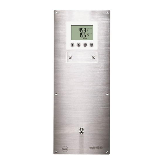
4 Transmitter 4.2. Product description 4.2.1. At a glance 1 Sealing plugs on the positive pressure test connection (Ø 4 mm) 2 Sealing plugs on the negative pressure test connection (Ø 4 mm) 3 Socket for service plug 4 Display (optional) 5 Keys (only with optional display) 6 Test rods for the analog... -
Page 14: Display And Keypad
(Ø 6.4 mm) 4.2.2. Display and keypad The display option allows operation of the testo 6383 transmitter via the display and four keys. The LCD display consists of two 7-segment lines for displaying readings and units and of an information line (for status messages, for example). -
Page 15: Analog Outputs
Only have the transmitter wired and connected by authorized personnel with the voltage disconnected. 4.2.5. Analog outputs As analog outputs, the testo 6383 has either • 1 current output of 0 to 20 mA (4-wire)/4 to 20 mA (4-wire) or •... -
Page 16: Alarm Handling
The testo 6383 monitors limit values with the help of relays. If a reading is outside the limit values, a relay to be specified by the user is switched. -
Page 17: Commissioning
Mounting preparations 1. Create a wall opening (approx. 120 mm x 220 mm) at the mounting location. 2. Hold 6383 in assembly position and mark the drill holes. 3. Drill holes suitable for the screws to be used. 4. Connect 6383. -
Page 18: Connecting The Instrument
4 Transmitter 4.3.2. Connecting the instrument WARNING Electrical voltage Danger of injury! > De-energize the mains connection before connecting the transmitter. Only have the transmitter wired and connected by authorized personnel with the voltage disconnected. 4.3.2.1. Overview of terminals 1 Terminal strip for voltage supply and analog outputs 2 Relay terminal strip (option), below the relay cover... -
Page 19: Connecting Voltage Supply And Analog Outputs
4 Transmitter 4.3.2.2. Connecting voltage supply and analog outputs Terminal strip for voltage supply and analog outputs, item (1) of overview of terminals Channels 2 and 3 shown on the pin assignment plan cannot be used with this instrument. Wiring diagram for 4-wire system (0 to 20 mA/4 to 20 mA/0 to 1 V/0 to 5 V/0 to 10 V) 1 1 channel, 0 to 20 mA/4 to... -
Page 20: Connecting The Relay Outputs
4 Transmitter 3. Tie together each of the two adjacent cores using a cable tie. 4. Attach terminal strip for voltage supply and analog outputs. 4.3.2.3. Connecting the relay outputs Only have the transmitter wired and connected by authorized personnel with the voltage disconnected. Relay terminal strip, item (2) of overview of terminals... - Page 21 4 Transmitter • The insulation of the cable must be fed at least 5 mm (4) into the relay tray up to the elevated part. Use of relay as NC contact (NC = normally closed) 1 Alarm/status light (example of installation) 2 250 V AC/DC, 3 A The busy light (alarm/status light) is permanently on until the relay opens or the circuit is interrupted.
-
Page 22: Connecting Pressure Connections
4 Transmitter 4.3.2.4. Connecting pressure connections Illustration shows delivery status Use of front pressure connection 1. Remove hose from hose holder (2) and connect to overpressure (3) or underpressure (1) connection. 2. Connect remaining pressure connection to (3) or underpressure potential (1) with additional hose. -
Page 23: Assembling The Instrument
Assembling the instrument 1. Slide Ethernet connector into Ethernet socket. 2. Pull sealing frame (1) over the edge of the 6383. 3. Screw on 6383. Initially, only tighten the screws slightly. When all screws are in position, also align 6383 and tighten the screws. -
Page 24: Ethernet Communication
The type of operation can be set via the operating menu: Settings Ethernet Mode • Saveris Probe Mode: a corresponding testo 6383 becomes a Saveris participant • XML Server Mode: a corresponding testo 6383 can be integrated into unlimited Ethernet systems 4.3.4.2. -
Page 25: Integration Into Customer's Ethernet System
• Select Saveris Viewer (restricted functionality). The selection is available if the Saveris Viewer is installed. The program window Testo Saveris software is opened with the dialog Select project. Should the Software not start, check in the service s administration of the operating system whether the service testo tdassvcs is started, and if necessary, restart. - Page 26 XML file is the next page) located H:/wget/wget-complete-stable /wget --post-file= C:/usersettings.xml 254.169.100.100/config/ setusersettings The Ethernet module supports reading out of • Readings • Instrument type (testo 6383) • Firmware date and version (testo 6383) • Status and status messages (testo 6383)
- Page 27 Service hour counter (testo 6383) as well as the reading and writing of the: • Adjustment data (testo 6383) • Configuration data of analog outputs (testo 6383) • Configuration data of relays (testo 6383) • User settings (testo 6383) XML codes (download) The table of xml-codes is available for download www.testo.com/download-center...
- Page 28 4 Transmitter Answer (see Description Parameter Appendix) /config/getoptions Read off options of options.xml transmitter /config/getcollectivealarm Read off alarm messages collectivealarm.xml of transmitter Upload XML documents Description Parameter Post Answer (see Appendix) /config/setusersettings Perform settings of usersettings.xml usersettings.xml transmitter param=0 (adjustment /config/setcalibration Set adjustment data of calibration.xml...
- Page 29 4 Transmitter XML tag Description Type attenuation Damping (0 - 15) Numerical, decimal number cal_offset Offset Numerical, whole number cal_scale Parent element. Contains the child elements cal_minscale, cal_maxscale cal_minscale Scaling value Numerical, decimal number cal_maxscale Scaling value Numerical, decimal number Elements in collectivealarm.xml XML tag Description...
- Page 30 4 Transmitter Elements in laststatusmessage.xml XML tag Description Type mufmsg Base element. Contains the child elements msg, sn, hours Status message ASCII Serial number ASCII, 8 characters hours Service hour counter in h Numerical, whole number Elements in onlinevalue.xml XML tag Description Type online_values...
- Page 31 4 Transmitter Elements in serialnumber.xml XML tag Description Type serialnumber Base element. Contains the child element number number Serial number ASCII, 8 characters Elements in status.xml XML tag Description Type mufstatus Base element. Contains the child elements statemsg, staterel, statecounter Status message statemsg Numerical, whole number...
- Page 32 4 Transmitter XML tag Description Type Language language Numerical, whole number 0 ->German 1 ->English 2 ->French 3 ->Spanish 4 ->Italian 5 ->Japanese 6 ->Swedish Status messages display disp_msg Numerical, whole number 0 = off 1 = on Pressure process data, absolute abs_pressure_pa_process, Numerical, decimal number pressure in Pa...
- Page 33 4 Transmitter XML tag Description Type meas_status Parent element. Contains the child elements min, max, mean connector_info Channel (transmitter) ASCII channel_type Parameter details ASCII min. Minimum reading Numerical, decimal number max. Maximum reading Numerical, decimal number mean Mean value Numerical, decimal number production_options description Content of production_options is a double word type number (32 bit).
- Page 34 2 0=relay 3 is not set 1=relay 3 is set 3 0=relay 2 is not set 1=relay 2 is set 4 0=relay 1 is not set 1=relay 1 is set More information can be found in the download area at www.testo.com.
-
Page 35: Adjusting The Instrument
3. Contact ch. 3 (non-functional) 4. Service interface Adjusting analog output 1 ✓ With testo 6383 with current output: Load of max. 500 Ω is connected to channel 1. ✓ A precise multimeter (minimum requirement: resolution 6.5 digits, at least 5-times more accurate than the 6383) is available. -
Page 36: N-Point Adjustment
77) or enter it via the user menu (see Performing analog adjustment, page 48). 3. Disconnect connections between the multimeter and the contacts of the testo 6383 and close the service cover. 4.3.5.2. n-point adjustment With an n-point adjustment, the parameters at the 3-6 measurement points are adjusted to the reference value. -
Page 37: Operation
4.4.1. Relationship between user menu and mini-DIN socket is active The testo 6383 can be parameterized using either the user menu or the P2A software (see Parameterizing, adjusting and analyzing software (P2A software) page 55). The testo 6383 transmitter can only be operated via the display and keypad if the display option is available. - Page 38 4 Transmitter 1 Channel 1 display 2 No display 3 Display for messages Four keys enable the user to navigate/scroll through the menus and enter/amend values and settings: Function/description • In Measuring Mode: changes to parameterization • In Parameterizing Mode: confirms a selection or setting •...
-
Page 39: Overview Of The Testo 6383 User Menu
4 Transmitter 4.4.4. Overview of the testo 6383 user menu... - Page 40 4 Transmitter...
-
Page 41: The Individual Main Menus
The individual main menus 4.4.5.1. Editing main menu of channel 1 An overview is given in Overview of the testo 6383 user menu, page 39). You can perform basic settings for channel 1. 1. In the Measuring Mode press SET, select Main Menu with ... - Page 42 4 Transmitter limit values, you can choose between monitoring the minimum or maximum value and set a limit value and hysteresis for each alarm. In addition, every alarm can be linked to a clearly visible visual alarm (display background lighting and the corresponding measurement value flash when limit values are violated).
-
Page 43: Editing Main Menu Settings
If an alarm is assigned to the collective alarm, the relay is switched and a visual alarm can be issued via the display as soon as (at least) one of the warning or error messages of the testo 6383 transmitter becomes active. - Page 44 4 Transmitter Editing display settings You can set the brightness and contrast of the display. with or and confirm selection with 1. Select Display Settings SET. with or and confirm 2. Select Backlight Contrast selection with SET. One of the following parameters can now be selected using ...
-
Page 45: Editing Main Menu Analysis
ESC. 3. Accept setting by pressing and test with multimeter (minimum requirement: resolution 6.5 digits, at least 2-times more accurate than the 6383) as follows: Analog output 1: Via test contacts under service flap, see diagram. - Page 46 4 Transmitter 1 Channel 1 test contacts 2 Service interface 3 Multimeter and use or to 4. Return to Test Analog Output with continue to Test Relay Output. Testing functionality of the pressure sensor (Test pressure sensor) This function is only required to calibrate the pressure sensor.
-
Page 47: Editing Message Main Menu
4 Transmitter 4.4.5.5. Editing Message main menu Messages can be confirmed/acknowledged, the last messages can be called up and the display of the messages can be switched on or off. 1 Operating hours at the time of message 2 Message code (see Status, warning and error messages, page 50). -
Page 48: Calling Up Main Menu Ident
4 Transmitter 10. Continue to Main Menu Ident with or or return to Measuring Mode with ESC. An overview of the messages can be found in Status, warning and error messages, page 50 4.4.5.6. Calling up Main Menu Ident 1 Instrument type 2 Build number 3 Firmware... -
Page 49: Editing Reset Main Menu
4 Transmitter 4. Press SET. Read off multimeter display and enter this value in the user menu. Do this by scrolling one digit to the right using and increasing the value of digit by 1 using . Confirm with or abort entry with ESC. -
Page 50: Status, Warning And Error Messages
In the transmitter, the last 60 status messages and the last 120 error and warning messages are stored in a ring memory. There is no limit in the P2A software. 4.5.1. Status messages Status messages show the current operating status of the testo 6383. Message Display Description... -
Page 51: Warning Messages
4 Transmitter Message Display Description 01D19 Service plug The Mini-DIN socket is connected to: the USB adapter for P2A software, the adjustment adapter or the service plug (is not recorded/no number) 00300 New limit value The limit value has been changed or shifted 00301 Scaling changed... -
Page 52: Transmitter Error Messages
Cause Remedying of fault 01505 Watchdog error Due to a processor If the problem occurs error, the transmitter frequently, contact performs an automatic Testo Service. restart. 01115 Low adjustment The ambient Take necessary temperature temperature is too low measures to raise... -
Page 53: Status Code In Cyclical Service
4 Transmitter 4.5.4. Status code in cyclical service Status codes for error messages Message in hex Description Cause notation 0x0C Transmitter error • Supply voltage too • Ambient temperature too high • Ambient temperature too low • Restart of the transmitter is being performed. -
Page 54: Namur Fault Conditions
4 Transmitter Shown on the Can be used for Additional display collective alarm message end Transmitter reset Analog adjustment T ambient high T ambient low Supply voltage low Watchdog error Perform the Confirm message function (acknowledgement of the alarm via the control keys on the transmitter): •... -
Page 55: Maintenance And Cleaning
Specifications The P2A software is used for the parameterizing, adjustment and analysis of testo transmitters. The following applies: • Generally, all newer testo transmitters (as of 2007) are supported. • For each newly purchased Testo transmitter, a free software upgrade must be installed, containing the instrument drivers for all transmitters which are connectable at that time. -
Page 56: Functions And Use
5 Parameterizing, adjusting and analyzing software (P2A software) The software must only be bought one time, even for owners of several testo transmitters. 5.1.1. Functions and use In the P2A software, two different file types are used: The instrument and the parameter file. -
Page 57: Scope Of Delivery
USB driver CD. 5.2.1.3. P2A software upgrade 1. Download and store P2A software upgrade from www.testo.com/download-center (requires registration). 2. Select folder into which the downloaded Zip file was stored, and unzip the file. 3. Start file... -
Page 58: Starting The Software
5.2.2.1. Starting the program > Click on [Start] Programs (Windows XP) or All Programs (Windows Vista, Windows 7) | Testo P2A- Software. In Windows Vista/Windows 7 the window User account control is opened when starting the software the first time. -
Page 59: Using The Software
5 Parameterizing, adjusting and analyzing software (P2A software) 5.3. Using the software 5.3.1. User interface 1 Menu bar: Menu Command Explanation Shows the Windows dialogue for File Open searching and opening files. Save as Saves the parameters of an instrument or parameter file under a new name. - Page 60 5 Parameterizing, adjusting and analyzing software (P2A software) Menu Command Explanation Check instrument Checks the connections to a connections connected instrument without the instrument having to be activated. Service A text file with the most important information on the computer and the software is opened via Display service data.
-
Page 61: Editing Instrument/Parameter File
5 Parameterizing, adjusting and analyzing software (P2A software) [Change parameterization] see Changing instrument/parameter file page 61. [Test/analyze transmitter] see Chapter Analyzing/testing the transmitter page 71. [Adjusting the transmitter] see Chapter Adjusting the transmitter page 75. [Transmitter history] see Transmitter history page 78. 5 File information: Status Shown in the window... - Page 62 5 Parameterizing, adjusting and analyzing software (P2A software) 2. Change or enter parameters in the corresponding fields. Field Explanation Unit/ All analog outputs are parameterized in this mask. Analog output Unit/analog output Unit: 0 to 1 V/5 V/10 V or 0 to 20 mA/4 to (graphic) 20 mA.
- Page 63 5 Parameterizing, adjusting and analyzing software (P2A software) Field Explanation Unit Selection of the physical unit. When changing the unit, standard values are set for scale minimum and maximum. Caution! When changing the phys. unit, the relay limit values are set to the assigned default values. Signal delay Curve changes according to the set signal (graphic)
- Page 64 5 Parameterizing, adjusting and analyzing software (P2A software) Field Explanation Limit values, relay 1 to 4/alarm In this mask, the relays or display values, alarm 1 to 4 alarms are parameterized. Relay x/alarm x Four relays or alarm values are available (optional).
- Page 65 5 Parameterizing, adjusting and analyzing software (P2A software) Field Explanation Max control If switched to ON (NO contact) or OFF (NC contact) above the limit value; in the event of a subsequent undershooting of Limit value minus Hysteresis, it is switched to OFF (NO contact) or ON (NC contact).
- Page 66 5 Parameterizing, adjusting and analyzing software (P2A software) Field Explanation Alarm delay The desired alarm delay for the alarms of the min/max control and the visual alarm is entered in the input field (0 to 3600 seconds possible). The alarm delay has no effect on the collective alarms.
- Page 67 Valid password Display of the current password. Button Explanation Ethernet Networking the transmitters via Ethernet. For a multitude of applications, measurement data can be simultaneously recorded, documented and visualized. Address allocation of the testo 6383 with Start wizard... Ethernet module:...
- Page 68 Transmitter IP address Prior to the automatic allocation of the IP address, the network cable must be connected to the transmitter. IP address of the Address allocation of the testo 6383 with device Ethernet module: Manual • Define the IP address of the transmitter •...
-
Page 69: Saving Parameters
The original name (Instrument type, Serial number) is suggested with the current date/time as standard, e.g. "testo 6383 01234578 061120 1403.cfp". For a standard installation, the files are saved under "C:\Documents and Settings\All Users\Shared Documents\P2A Software". The path can differ depending... -
Page 70: Opening The Parameter File
5 Parameterizing, adjusting and analyzing software (P2A software) 5.3.2.3. Opening the parameter file All parameter files stored in the standard directory path are automatically displayed in the file list when the software is started. You can also open parameter files that are stored in other directories. -
Page 71: Analyzing/Testing The Transmitter
5 Parameterizing, adjusting and analyzing software (P2A software) ✓ Transmitter must be connected. Click on File > New connection in the menu bar. Connection to the transmitter is established. 5.3.3. Analyzing/testing the transmitter In this section, you can test the outputs of the connected instrument, read off the limit values and reset the parameters to the factory settings. -
Page 72: Testing Analog Output
5 Parameterizing, adjusting and analyzing software (P2A software) The values are reset to the customer-specific factory settings. 4. Click on [OK] [Cancel] to close the dialogue. 5.3.3.3. Testing analog output ✓ The required instrument file is marked. 1. Click on [Test/analyze transmitter]. -
Page 73: Testing Switch Output Relays 1 To 4
5 Parameterizing, adjusting and analyzing software (P2A software) Field/button Explanation [Activate] The entered default value is forwarded to the corresponding analog output and to the test contacts by clicking. A warning informs that the value is being transmitted to the connected instrument in the event of existing cabling. -
Page 74: Displaying Min./Max. Values
5 Parameterizing, adjusting and analyzing software (P2A software) 2. Mark Relay tests and test the values. Field/button Explanation Test the relay function (see Testing functionality of relay outputs, page 46). [Activate relay n] Close contact. A warning informs that the value is being transmitted to a connected PLC, external display, etc. -
Page 75: Adjusting The Transmitter
5 Parameterizing, adjusting and analyzing software (P2A software) 2. Mark Min./max. values. Field/button Explanation Min./max. values View the min./max. values of each channel. Only the values within the measuring range are shown. Channel Channel 1 min./max. Value Min. or max. value, 1 decimal place. Unit Unit selected in Unit/analog... -
Page 76: N-Point Adjustment
5 Parameterizing, adjusting and analyzing software (P2A software) 5.3.4.1. n-point adjustment 1. Connect precision pressure sensor (see n-point adjustment, page 36). 2. Mark the instrument file of the connected instrument. 3. Click on [Adjusting the transmitter]. Properties of <Instrument type> <Serial number> dialogue is opened with the Adjusting the transmitter register. -
Page 77: Adjusting The Analog Output
5 Parameterizing, adjusting and analyzing software (P2A software) 5.3.4.2. Adjusting the analog output 1. Connect precision multimeter (see ). 2. Mark the instrument file of the connected instrument. 3. Click on [Adjusting the transmitter]. Properties of <Instrument type> <Serial number> dialogue is opened with the Adjusting the transmitter register. -
Page 78: Transmitter History
5 Parameterizing, adjusting and analyzing software (P2A software) Field Explanation Measured analog Required field: Entry of the value read off at value the multimeter. 5.3.5. Transmitter history Parameterizations, adjustment processes and messages that have occurred are registered in the transmitter with an operating hours stamp. - Page 79 5 Parameterizing, adjusting and analyzing software (P2A software) 3. Click on the required entry in the list to change the display. Field Explanation Operating hours / Operating hour/time stamp at which the date/time change at the instrument was performed. User Name with which the user is logged into the operating system.
- Page 80 5 Parameterizing, adjusting and analyzing software (P2A software) Field Explanation Selection: Analog adjustments. Operating hours / Operating hour/time stamp at which the date/time change at the instrument was performed. Name with which the user is logged into the User operating system. "Transmitter"...
- Page 81 5 Parameterizing, adjusting and analyzing software (P2A software) Field Explanation The table is shown only for error and status messages that were generated in the transmitter and were transferred and saved there via the connection to the P2A software. Operating hour Operating hour at which the message appeared in the instrument.
-
Page 82: Tips And Assistance
After approx. 20 seconds current reading appear? If we could not answer your question, please contact your dealer or Testo Customer Service. For contact details see the rear side of this document or the web page www.testo.com/service-contact 6.2. Accessories and spare parts Description Article no. -
Page 83: Ordering Options For Testo 6383 Transmitter (0555 6383)
For a complete list of all accessories and spare parts, please refer to the product catalogues and brochures or look up our website at: www.testo.com 6.2.1. Ordering options for testo 6383 transmitter (0555 6383) Order code Characteristic Axx Measuring range... - Page 84 With display/Italian With display/Japanese With display/Swedish Dxx Integrated humidity probe No humidity/temperature probe Humidity/temperature probe integrated in panel Preparation for external humidity/temperature probe testo 6610 probe Exx Ethernet Without Ethernet interface With Ethernet interface Fxx Differential pressure unit Pa/Min/Max hPa/Min/Max...
- Page 85 6 Tips and assistance Order code Characteristic inch HG/Min/Max kg/cm /Min/Max PSI/Min/Max Gxx Optional analog output for humidity probe connection testo 6610/units % RH/Min/Max °C/Min/Max °F/Min/Max °C /Min/Max °F /Min/Max g/kg /Min/Max gr/lb /Min/Max /Min/Max gr/ft /Min/Max ppmV/Min/Max °C /Min/Max °F...
- Page 86 6 Tips and assistance Order code Characteristic 4 relay outputs, channel 1 limit values and collective alarm Ixx Units, channel 3 (only if optional humidity probe connection is available) % RH/Min/Max °C/Min/Max °F/Min/Max °C /Min/Max °F /Min/Max g/kg /Min/Max gr/lb /Min/Max /Min/Max gr/ft /Min/Max...
- Page 87 6 Tips and assistance...
- Page 88 0970 6386 en 02 V01.12-V01.70-1 en...
Need help?
Do you have a question about the 6383 and is the answer not in the manual?
Questions and answers