
Related Manuals for TESTO 6351


Summary of Contents for TESTO 6351
- Page 1 6351 · differential pressure transmitter P2A software · Parameterizing, adjusting and analyzing software Instruction manual...
-
Page 3: Safety And The Environment
Use only original spare parts from Testo. Any additional work must only be carried out by authorized personnel. Otherwise testo will not accept any responsibility for the proper functioning of the instrument after repair and for the validity of certifications. -
Page 4: About This Document
2 About this document About this document > Please read this documentation through carefully and familiarize yourself with the product before putting it to use. Pay particular attention to the safety instructions and warning advice in order to prevent injuries and damage to the products. >... -
Page 5: Table Of Contents
3 Contents Contents Safety and the environment ............. 3 About this document ..............4 Contents .................. 5 Transmitter ................8 4.1. Specifications ................ 8 4.1.1. Functions and use ......................8 4.1.2. Scope of delivery ......................8 4.1.3. Accessories ........................8 4.1.4. - Page 6 3 Contents 4.4.5. Overview of the testo 6351 user menu ..............33 4.4.6. The individual main menus ..................36 4.4.6.1. Editing main menu of channel 1 ..............36 4.4.6.2. Editing Main Menu Alarm ................36 4.4.6.3. Editing Main Menu Settings ............... 39 4.4.6.4.
- Page 7 5.3.4.2. Adjusting the analog output ..............74 5.3.5. Transmitter history ....................75 Tips and assistance ..............80 6.1. Questions and answers ............80 6.2. Accessories and spare parts ..........80 6.2.1. Ordering options for testo 6351 transmitter (0555 6351).......... 81...
-
Page 8: Transmitter
Complex room climate applications • Monitoring flow velocities or volumetric flow rates in air conditioning systems 4.1.2. Scope of delivery The scope of delivery of the testo 6351 transmitter includes the following: • Key cover • Rear panel bracket •... -
Page 9: Technical Data
4 Transmitter 4.1.4. Technical data Parameter • Differential pressure Accuracy The specifications are only valid if the positive pressure is applied at the positive pressure connection. • ±0.8 % of measuring range final value, additional ±0.3 Pa intrinsic error • = 0.03 % of measuring range per degree Kelvin of K slope drift deviation from nominal temperature 22 °C... - Page 10 2500 hPa Upon delivery and following a factory reset the readings are shown in the display in the unit that was ordered via the KMAT option Fxx, see 6.2.1. Ordering options for testo 6351 transmitter (0555 6351). Meas. cycle •...
- Page 11 4 Transmitter Maximal load • 4-wire: 10 kΩ (voltage output) Analog output • 0 to 1 V ± 1.5 mV (4-wire) or • 0 to 5 V ± 7.5 mV (4-wire) or • 0 to 10 V ± 15 mV (4-wire) or •...
-
Page 12: Dimensions
4 Transmitter Process temperature • -20 to 65 °C/-4 to 149 °F Housing, weight • Plastic, 0.7 kg • Optional Ethernet intermediate layer: 0.6 kg Protection class • IP 65 only if the transmitter is wired and/or sealing plugs are inserted Directives, standards and tests •... -
Page 13: Product Description
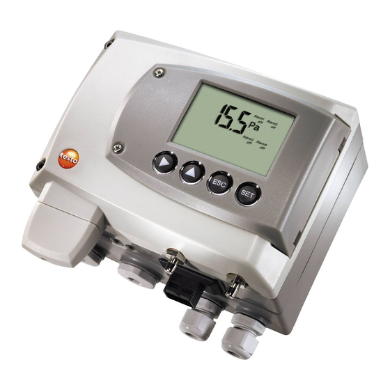
4 Transmitter 4.2. Product description 4.2.1. At a glance 1 Keys (only with optional display) 2 Service flap screw connection (self-locking, 2 pcs.) 3 Display (optional) 4 Service flap 5 Negative pressure connection 6 Positive pressure connection, marked with a red washer 7... - Page 14 4 Transmitter 15 Housing screws 16 Hole for fastening to rear panel bracket (M3 x 6 screw) 17 Plastic bracket for assembly on rear panel...
-
Page 15: Display And Keypad
4 Transmitter 4.2.2. Display and keypad The display option allows operation of the testo 6351 transmitter via the display and four keys. The LCD display consists of two 7-segment lines for displaying readings and units and of an information line (for status messages, for example). -
Page 16: Parameters
4 Transmitter 4.2.6. Parameters The following parameters are displayed: • Differential pressure in Pa, hPa, kPa, mbar, bar, mmH O, inch O, inch HG, kg/cm , PSI • Flow in m/s, ft/min • Volumetric flow rate in m /h, l/min, Nm /h, Nl/min •... - Page 17 4 Transmitter Measuring Maximum scaling range/standard scaling 0 to 50 Pa -25 to 75 Pa 0 to 100 Pa -50 to 150 Pa 0 to 500 Pa -250 to 750 Pa 0 to 10 hPa -5 to 15 hPa 0 to 50 hPa -25 to 75 hPa 0 to 100 hPa -50 to 150 hPa...
-
Page 18: Alarm Handling
The testo 6351 monitors limit values with the help of relays. If a reading is outside the limit values, a relay to be specified by the user is switched. -
Page 19: Connecting The Instrument
4 Transmitter 3. Drill three holes (Ø 5 mm) and insert dowels where necessary. 4. Screw on rear panel bracket. Remember that the clamping brackets (1) must face the wall. Fastening instrument to rear panel bracket 1. Slide plastic bracket (2) on the back of instrument onto rear panel bracket until it engages (see arrows). - Page 20 4 Transmitter 1. Loosen screw connection (1) of service flap and open the flap. 2. Loosen and remove housing screws (2). 3. Remove upper part of housing from lower part (3) and place on a clean surface. WARNING Electrical voltage Danger of injury! >...
-
Page 21: Overview Of Terminals
4 Transmitter 4.3.2.1. Overview of terminals 1 Lower part of housing 6 Terminal board 2 Relay board (option) 7 M 16 x 1.5 screw connection* 3 Relay terminals 8 Eyelet for measuring point panel 4 Insulating trough for relay 9 M 20 x 1.5 screw connection* board 5... -
Page 22: Connecting Voltage Supply And Analog Outputs
4 Transmitter 4.3.2.2. Connecting voltage supply and analog outputs Terminal strip for voltage supply and analog outputs, item (5) of 4.3.2.1. overview of terminals Channels 2 and 3 shown on the circuit board cannot be used with this instrument. 1. Disconnect connector. 2.... -
Page 23: Connecting The Relay Outputs
4 Transmitter position close by and be marked as such. 1. Disconnect connector. 2. Strip the cable ends, clamp wire end ferrules on and screw to channel terminals as shown in diagram. 3. Insert connector into socket. 4.3.2.3. Connecting the relay outputs Only have the transmitter wired and connected by authorized personnel with the voltage disconnected. - Page 24 4 Transmitter Connection note • For the connection, a double-insulated mains cable (sheathed cable) with a cross-section of at least 1.5 mm² must be used. • Cable connection (2) may not be routed in a loop within the tray (1). •...
- Page 25 4 Transmitter Use of relay as NC contact (NC = normally closed) 1 Alarm/status light (example of installation) 2 250 V AC/DC, 3 A The busy light (alarm/status light) is permanently on until the relay opens or the circuit is interrupted. This circuit can therefore be used to monitor the functionality of the alarm circuit, as a cable break, for instance, is indicated by the busy light going off.
-
Page 26: Plug-In Connection Option
4 Transmitter 4.3.2.4. Plug-in connection option As an option, the PG screw connections of the signal and supply lines can be replaced with plug-in connections that are installed at the housing, see item 1 and 2. The relay cabling occurs via standard cable entries and PG screw connections, see item 3 and Plug-in connections for power supply and channels M12 plug-in connection (5-pin) socket (item 1) -
Page 27: Closing The Instrument
4 Transmitter 4.3.2.5. Closing the instrument 1. Place upper part of instrument on top of lower part (see arrow) and fix in place with housing screws (1). -
Page 28: Adjusting The Instrument
4 Transmitter 2. Close the service flap and tighten screws (2). 4.3.3. Adjusting the instrument 4.3.3.1. Analog output adjustment The purpose of adjusting the analog outputs is to adjust the signal chain from the digital signal (within the transmitter) to the analog outputs. -
Page 29: N-Point Adjustment
4 Transmitter 4. Service interface Adjusting analog output 1 ✓ With testo 6351 with current output: Load of max. 500 is connected to channel 1 (see Plug-in connections for power supply and channels, page 26) ✓ A precise multimeter (minimum requirement: resolution 6.5 digits, at least 5-times more accurate than the 6351) is available. -
Page 30: Operation
4.4.1. Relationship between user menu and mini-DIN socket is active The testo 6351 can be parameterized using either the user menu or the P2A software (see 5. Parameterizing, adjusting and analyzing software (P2A software)). The testo 6351 transmitter can only be operated via the display and keypad if the display option is available. -
Page 31: Key Cover
4 Transmitter 4.4.2. Key cover To prevent unauthorized operation of the keys, the standard key frame can be replaced with a key cover. If the key cover has been assembled, the service flap must be opened for operation. Attaching the key cover ✓... -
Page 32: Structure Of User Menu
4 Transmitter 4.4.4. Structure of user menu At the main menu level, the user menu comprises the following: • Main Menu Channel 1 • Main Menu Alarm • Main Menu Settings • Main Menu Analysis • Main Menu Messages • Main Menu Ident •... -
Page 33: Overview Of The Testo 6351 User Menu
4 Transmitter 4.4.5. Overview of the testo 6351 user menu... - Page 34 4 Transmitter...
- Page 35 4 Transmitter...
-
Page 36: The Individual Main Menus
4.4.6. The individual main menus 4.4.6.1. Editing main menu of channel 1 An overview is given in 4.4.5.Overview of the testo 6351 user menu). You can perform basic settings for channel 1. 1. In the Measuring Mode press SET, select... - Page 37 4 Transmitter In addition, every alarm can be linked to a clearly visible visual alarm (display background lighting and the corresponding measurement value flash when limit values are violated). An alarm delay between 0 and 3600 seconds can still be assigned to every alarm used for limit value monitoring so that both the corresponding relay effect and the visual alarm are delayed.
- Page 38 If an alarm is assigned to the collective alarm, the relay is switched and a visual alarm can be issued via the display as soon as (at least) one of the warning or error messages of the testo 6351 transmitter becomes active.
-
Page 39: Editing Main Menu Settings
4 Transmitter 4.4.6.3. Editing Main Menu Settings You can edit instrument settings and other settings. > In Measuring Mode, press SET, select Main Menu Settings using or and confirm selection with SET. You can edit settings for: • Display •... - Page 40 4 Transmitter Selecting language You can select the language for the plain text line in the display. > Press SET, select required language with or , confirm selection with and return to Language. Only choose a language that you can understand well. Select unit This setting affects the unit of the standard and process data.
-
Page 41: Editing Main Menu Analysis
ESC. 3. Accept setting by pressing and test with multimeter (minimum requirement: resolution 6.5 digits, at least 2-times more accurate than the 6351) as follows: Analog output 1: Via test contacts under service flap, see diagram. - Page 42 4 Transmitter 1 Channel 1 test contacts 2 Service interface 3 Multimeter 4. Return to Test Analog Output with and use or to continue to Test Relay Output. Testing functionality of the pressure sensor (Test pressure sensor) This function is only required to calibrate the pressure sensor.
-
Page 43: Editing Message Main Menu
4 Transmitter 4.4.6.5. Editing Message main menu Messages can be confirmed/acknowledged, the last messages can be called up and the display of the messages can be switched on or off. 1 Operating hours at the time of message 2 Message code (see 4.6. Status, warning and error messages). -
Page 44: Calling Up Main Menu Ident
4 Transmitter with or and confirm selection with SET. 8. Select 9. Return to Main Menu Message with ESC. with or or return to 10.Continue to Main Menu Ident Measuring Mode with ESC. An overview of the messages can be found in 4.5. Status, warning and error messages. - Page 45 4 Transmitter 3. Use or to select Adj. Point 4. Press SET. Read off multimeter display and enter this value in the user menu. Do this by scrolling one digit to the right using and increasing the value of digit by 1 using . Confirm with or abort entry with ESC.
-
Page 46: Editing Reset Main Menu
Warning messages • Error messages in each case for the testo 6351 transmitter. All messages are stored in the transmitter with an operating hours stamp. Use the user menu (see4.4.6.5. Editing Message main menu) or the P2A software (see 5.3.5. Transmitter history) to view the message history. -
Page 47: Status Messages
4 Transmitter 4.5.1. Status messages Status messages show the current operating status of the testo 6351. Message Display Description 02506 Sensor Message appears while the initialization transmitter is starting up. If the message disappears, the transmitter is ready for operation. -
Page 48: Warning Messages
4 Transmitter 4.5.2. Warning messages Warning messages show an early warning or a current malfunction which may negatively impact measuring. Message Display Cause Remedying of fault 00E00 T ambient high The ambient Take necessary temperature exceeds measures to lower the permissible ambient temperature, temperature for the e.g. -
Page 49: Transmitter Error Messages
Cause Remedying of fault 01505 Watchdog error Due to a processor If the problem occurs error, the transmitter frequently, contact performs an automatic Testo Service. restart. 01115 Low adjustment The ambient Take necessary temperature temperature is too low measures to raise... -
Page 50: Namur Fault Conditions
4 Transmitter Shown on the Can be used for Additional display collective alarm message end Analog adjustment T ambient high T ambient low Supply voltage low Watchdog error Perform the Confirm message function (acknowledgement of the alarm via the control keys on the transmitter): •... -
Page 51: Maintenance And Cleaning
4 Transmitter 4.6. Maintenance and cleaning 4.6.1. Maintaining the instrument We recommend that the adjustment and settings of the transmitter be checked at regular intervals using the • User menu (4.4. Operation) or • P2A software (5. Parameterizing, adjusting and analyzing software (P2A software)) Convenient "remote monitoring"... -
Page 52: Parameterizing, Adjusting And Analyzing Software (P2A Software)
Specifications The P2A software is used for the parameterizing, adjustment and analysis of testo transmitters. The following applies: • Generally, all newer testo transmitters (as of 2007) are supported. • For each newly purchased Testo transmitter, a free software upgrade must be installed, containing the instrument drivers for all transmitters which are connectable at that time. -
Page 53: System Requirements
5 Parameterizing, adjusting and analyzing software (P2A software) Parameter files are ".cfp" format files. 5.1.2. System requirements Operating system ® • Windows ® • Windows ® • Windows Computer The computer must fulfil the requirements of the respective operating system. The following requirements must additionally be fulfilled: •... -
Page 54: First Steps
Without the input of a licence key, the software will run only as a demo version (time limit 30 days). 1. You can download the software under the following link: https://www.testo.com/download-center. If the installation program does not start automatically: > Open download folder and start P2A.exe. -
Page 55: Establishing A Connection With The Instrument
Without the input of a licence key, the software will run only as a demo version (time limit 30 days). 4. You can download the software under the following link: https://www.testo.com/download-center. If the installation program does not start automatically: > Open download folder and start P2A.exe. -
Page 56: Using The Software
5 Parameterizing, adjusting and analyzing software (P2A software) 5.3. Using the software 5.3.1. User interface 1 Menu bar: Menu Command Explanation File Open Shows the Windows dialogue for searching and opening files. Save as Saves the parameters of an instrument or parameter file under a new name. - Page 57 5 Parameterizing, adjusting and analyzing software (P2A software) Menu Command Explanation Check instrument Checks the connections to a connections connected instrument without the instrument having to be activated. Service A text file with the most important information on the computer and the software is opened via Display service data.
-
Page 58: Editing Instrument/Parameter File
5 Parameterizing, adjusting and analyzing software (P2A software) [Change parameterization] see 5.3.2.1. Changing instrument/parameter file. [Test/analyze transmitter] see 5.3.3. Chapter Analyzing/testing the transmitter. [Adjusting the transmitter] see 5.3.4. Chapter Adjusting the transmitter. [Transmitter history] see 5.3.5. Transmitter history. 5 File information: Status Shown in the window An instrument file is... - Page 59 5 Parameterizing, adjusting and analyzing software (P2A software) 2. Change or enter parameters in the corresponding fields. Field Explanation Unit/ All analog outputs are parameterized in this mask. Analog output Unit/analog output Unit: 0 to 1 V/5 V/10 V or 0 to 20 mA/4 to (graphic) 20 mA.
- Page 60 5 Parameterizing, adjusting and analyzing software (P2A software) Field Explanation Unit Selection of the physical unit. When changing the unit, standard values are set for scale minimum and maximum. Caution! When changing the phys. unit, the relay limit values are set to the assigned default values. Signal delay Curve changes according to the set signal (graphic)
- Page 61 5 Parameterizing, adjusting and analyzing software (P2A software) Field Explanation Limit values, relay 1 to 4/alarm In this mask, the relays or display values, alarm 1 to 4 alarms are parameterized. Relay x/alarm x Four relays or alarm values are available (optional).
- Page 62 5 Parameterizing, adjusting and analyzing software (P2A software) Field Explanation The graphic display in the centre of the screen refers to the relay wiring as a NO contact (ON). Hysteresis To avoid switching cycles. Channel Selection of the channel that is to be monitored.
- Page 63 5 Parameterizing, adjusting and analyzing software (P2A software) Field Explanation Basic settings Setting the pressure process data for Pitot tube measurement and standard data for volumetric flow rate measurement. Absolute pressure Absolute pressure existing in the process. The entered absolute pressure value is included in the Pitot tube calculation.
- Page 64 5 Parameterizing, adjusting and analyzing software (P2A software) Field Explanation Correction factor The correction factor enables an adjustment to the flow profile in the duct. The entered correction factor is included in the Pitot tube calculation. Absolute pressure The entered value and the selected unit are included in the calculation of the standard volumetric flow rate.
- Page 65 5 Parameterizing, adjusting and analyzing software (P2A software) Field Explanation Display Setting the display functions (if a display is available on the transmitter). Continuous display Display lighting is permanently switched on. lighting Display lighting When a particular button on the instrument is when button is pressed, the display lights up for 10 seconds.
-
Page 66: Saving Parameters
5 Parameterizing, adjusting and analyzing software (P2A software) Field Explanation [Adopt new Button for confirming the new password. password] Valid password Display of the current password. Field Explanation Zeroing cycle Setting the interval of the automatic zeroing with solenoid valve. The accuracy specifications are only valid for the zeroing cycle of 15 sec set by the factory. -
Page 67: Opening The Parameter File
5 Parameterizing, adjusting and analyzing software (P2A software) The original name (Instrument type, Serial number) is suggested with the current date/time as standard, e.g. "testo 6351 01234578 061120 1403.cfp". For a standard installation, the files are saved under "C:\Documents and Settings\All Users\Shared Documents\P2A Software". -
Page 68: Creating A New Instrument File
5 Parameterizing, adjusting and analyzing software (P2A software) 2. Select the command Delete in the context menu. The instrument or parameter file is deleted from the list. 5.3.2.6. Creating a new instrument file It is possible to create an instrument file without restarting the P2A software. -
Page 69: Testing Analog Output
5 Parameterizing, adjusting and analyzing software (P2A software) Properties of <Instrument type> <Serial number> dialogue is opened with the Test/analyze transmitter register. 2. Mark transmitter test. Current operating hours are shown. 3. Confirm control query to perform the reset. The values are reset to the customer-specific factory settings. 4.... - Page 70 5 Parameterizing, adjusting and analyzing software (P2A software) Field/button Explanation Default value Freely definable output value for the respective type of analog output (V or mA), 1 decimal place. [Activate] The entered default value is forwarded to the corresponding analog output and to the test contacts by clicking.
-
Page 71: Testing Switch Output Relays 1 To 4
5 Parameterizing, adjusting and analyzing software (P2A software) 5.3.3.4. Testing switch output relays 1 to 4 ✓ The required instrument file is marked. 1. Click on [Test/analyze transmitter]. Properties of <Instrument type> <Serial number> dialogue is opened with the Test/analyze transmitter register. -
Page 72: Displaying Min./Max. Values
5 Parameterizing, adjusting and analyzing software (P2A software) 5.3.3.5. Displaying min./max. values The transmitter saves the minimum or maximum value for each channel (measured since the last voltage supply or since the last manual reset). ✓ The required instrument file is marked. 1.... -
Page 73: Adjusting The Transmitter
5 Parameterizing, adjusting and analyzing software (P2A software) 5.3.4. Adjusting the transmitter This function is used to adjust an attached instrument. The following adjustments may be carried out using the software: • Analog adjustment (entry via assistant/wizard) • n-point adjustment (entry via assistant/wizard) Also see 4.4.6.7. -
Page 74: Adjusting The Analog Output
5 Parameterizing, adjusting and analyzing software (P2A software) Field Explanation How much pressure Required field: Entry of the value read off at is actually applied the pressure sensor. The n-point adjustment must always be carried out to its full extent and in good time at all selected adjustment points. The number of adjustment points (3 to 6) is stored in the user menu of the transmitter and can only be changed via the P2A software. -
Page 75: Transmitter History
5 Parameterizing, adjusting and analyzing software (P2A software) Field Explanation Default value The analog output value from the last performed adjustment is given at the output. Value of the factory adjustment: • Lower adjustment point: approx. 10 % of the max. value •... - Page 76 5 Parameterizing, adjusting and analyzing software (P2A software) is entered in the User field and only the operating hour is entered in the Date/time field instead of operating hour/date/time. For entries that are performed using the P2A software, the name of the user logged into Windows appears in the User field, while the date/time and operating hour are shown in Date/time...
- Page 77 5 Parameterizing, adjusting and analyzing software (P2A software) Field Explanation Operating hours / Operating hour/time stamp at which the date/time change at the instrument was performed. User Name with which the user is logged into the operating system. "Transmitter" entry if the change was performed at the instrument.
- Page 78 5 Parameterizing, adjusting and analyzing software (P2A software) Field Explanation Selection: Analog adjustments. Operating hours / Operating hour/time stamp at which the date/time change at the instrument was performed. Name with which the user is logged into the User operating system. "Transmitter"...
- Page 79 5 Parameterizing, adjusting and analyzing software (P2A software) Field Explanation The table is shown only for error and status messages that were generated in the transmitter and were transferred and saved there via the connection to the P2A software. Operating hour Operating hour at which the message appeared in the instrument.
-
Page 80: Tips And Assistance
After approx. 20 seconds current reading appear? If we could not answer your question, please contact your dealer or Testo Customer Service. For contact details see the rear side of this document or the web page www.testo.com/service-contact 6.2. Accessories and spare parts Description Article no. -
Page 81: Ordering Options For Testo 6351 Transmitter (0555 6351)
For a complete list of all accessories and spare parts, please refer to the product catalogues and brochures or look up our website at: www.testo.com 6.2.1. Ordering options for testo 6351 transmitter (0555 6351) Order code Characteristic Axx Measuring range... - Page 82 6 Tips and assistance Order code Characteristic -100 to 100 Pa -500 to 500 Pa -10 to 10 hPa -50 to 50 hPa -100 to 100 hPa -500 to 500 hPa -1000 to 1000 hPa -2000 to 2000 hPa Bxx Analog output/supply 0 to 1 V (4-wire, 24 V AC/DC) 0 to 5 V (4-wire, 24 V AC/DC)
- Page 83 6 Tips and assistance Order code Characteristic Fxx Differential pressure unit Pa/Min/Max hPa/Min/Max kPa/Min/Max mbar/Min/Max bar/Min/Max O /Min/Max inchH O /Min/Max inch HG/Min/Max kg/cm /Min/Max PSI/Min/Max m/s /Min/Max ft/min /Min/Max /h /Min/Max l/min /Min/Max /h /Min/Max Nl/min /Min/Max Hxx Relay Without relay 4 relay outputs, limit value monitoring 4 relay outputs, channel 1 limit values...
- Page 84 0970 6353 en 03...
Need help?
Do you have a question about the 6351 and is the answer not in the manual?
Questions and answers