Zehnder Rittling ComfoClime 24 Installer Manual
Hide thumbs
Also See for ComfoClime 24:
- Quick user manual (64 pages) ,
- User manual (30 pages) ,
- Installer manual (24 pages)

Related Manuals for Zehnder Rittling ComfoClime 24


Summary of Contents for Zehnder Rittling ComfoClime 24
- Page 1 ■ Decorative radiators ■ Comfortable indoor ventilation ■ Heating and cooling ceiling systems ■ Clean air solutions ComfoClime 24 ComfoClime 36 Installer manual 1 - EN...
-
Page 2: Table Of Contents
Table of Contents Preface ..................................3 1 Introduction ................................3 1.1 CE and UKCA declaration and warranty ......................3 1.1.1 Identification plate ............................3 1.1.2 Warranty ..............................4 1.1.3 Liability..............................4 1.2 Safety ................................4 1.2.1 Safety measures ............................5 2 For the Installer ................................6 2.1 ComfoClime configuration and dimensions ......................6 2.2 Technical specifications .............................7 2.3 Installation conditions ............................8 2.4 Installation of the ComfoClime ..........................9... -
Page 3: Preface
This manual provides all the information required for safe and optimal installation and maintenance of the Zehnder ComfoClime 24 or ComfoClime 36. It is also intended as a reference for servicing, so that this can be carried out in a responsible manner. -
Page 4: Warranty
Thermal Shield® is suitable for this purpose. ■ The air distribution system and the diffusers should be designed for a nominal air volume of at least 200m /h for the Comfoclime 24 and 315m /h for the ComfoClime EN - 4... -
Page 5: Safety Measures
1.2.1 Safety measures Always observe the local building, safety and installation guidelines of the municipality, utility companies or other authorities. The unit must be lifted or handled keeping into consideration and respecting the local safety regulations. Never lift the unit by yourself. The installation of the unit hanging on the wall is not permitted. -
Page 6: For The Installer
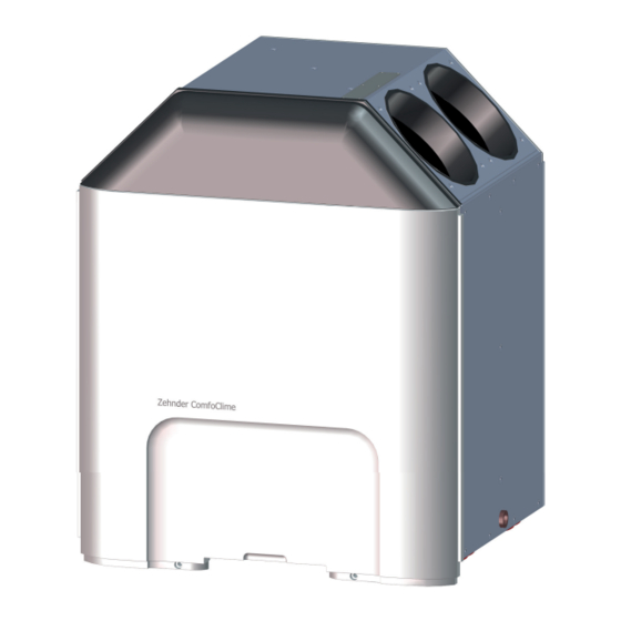
2 For the Installer 2.1 ComfoClime configuration and dimensions The standard ComfoClime configuration consists of: ■ 1 ComfoClime unit; ■ 1 cabled power supply plug; ■ 4 rubber ring seals; ■ 1 condensation drain cap; ■ 2 EPP standoffs; ■ 1 white plastic front cover; ■... -
Page 7: Technical Specifications
2.2 Technical specifications ComfoClime ComfoClime 24 ComfoClime 36 Performance Minimum airflow 200 m3/h 315 m3/h Maximum airflow 400 m3/h 600 m3/h Electrical connection details Maximum performance/power 1100 W 1100 W 230 V ± 10%, single phase, 230 V ± 10%, single phase,... -
Page 8: Installation Conditions
2.3 Installation conditions In case of retrofitting installation, is strongly suggested that the ComfoAir Q has the latest firmware with a minimum of release 1.10 otherwise proceed with a proper upgrade (see ComfoAir Q manual). In order to determine whether the ComfoClime can be installed in a certain area, the following aspects must be taken into account: ■... -
Page 9: Installation Of The Comfoclime
2.4 Installation of the ComfoClime 2.4.1 Transport and unpacking Contact your supplier immediately in case of damage or incomplete delivery and do not proceed with the installation. Take the necessary precautions when transporting and unpacking the ComfoClime unit. Only transport it in an upright position. Keep it upright when unpacking it. - Page 10 ■ 2 EPP standoffs; ■ 4 Rubber seals. EN - 10...
-
Page 11: Configuration Of The Unit
2.5 Configuration of the unit Legend ACRONYM MEANING Right layout Left layout Outdoor air intake Indoor supply air Indoor air extraction Outdoor air exhaust Consider the following schemes to connect the ducts: 2.6 Installation procedure During the installation, please take into consideration electromagnetic interferences. ■... - Page 12 The ComfoClime must be placed on top of the ComfoAir Q according to the following steps: Step Action Make sure that the ComfoAir Q is properly placed in its final position (see the ComfoAir Q installation manual) and not yet commissioned; Put the two EPP standoffs on the top part of ComfoAir Q as shown in the picture;...
- Page 13 Verify that the blue central rotary switch is in the proper position: • 0 for ComfoClime 36 • 1 for ComfoClime 24 • 2 for ComfoClime Q if necessary put it the right position using a flat screw driver; 13 - EN...
- Page 14 Step Action Unpack carefully the ComfoClime and place it over the ComfoAir Q respecting all the safety rules taking as reference the four pins on its bottom which have to fit in with the corresponding recesses in the EPP standoffs; WARNING! Never lift the unit alone.
- Page 15 Step Action Mount the plastic front cover A onto the unit. Check that the top of the plastic design front is properly matching the recesses and that it goes smoothly above the CAQ front plastic cover. Then fix the ComfoClime plastic front A with the two provided screw on top and the two on the bottom;...
- Page 16 Step Action Depending to the installation setting, the drain action will be different as shown in the following pictures: Installation with CAQ ERV (enthalpic exchanger) Installation with CAQ HRV (standard exchanger) EN - 16...
-
Page 17: Installation Of Air Ducts
2.6.2 Installation of air ducts CAUTION! Do not connect the ComfoAir Q nor the ComfoClime to the power supply until the end of the complete installation and the mutual connection of the units is done. The unit must not be mounted/hung on the wall. -
Page 18: Wiring Diagram Comfoclime
2.7 Wiring diagram ComfoClime ACL-in ACL-in ACN-in ACN-in COMM-drv COMM-drv COMM-drv COMM-drv 22 AWG COMP COMM-drv 22 AWG COMM-drv XP209 COMM-drv COIL XP211 DCN-blk DCN-blk ENVI XP212 N - out N - out L - out L - out CN12 CN12 CN17 CN16... -
Page 19: Commissioning The Comfoclime
2.8 Commissioning the ComfoClime After installation, the ComfoClime system must be commissioned. In case of retrofitting installation, is strongly suggested that the ComfoAir Q has the latest firmware with a minimum of release 1.10 otherwise proceed with a proper upgrade (see ComfoAir Q manual). Proceed with the unit activation according to the following steps: Step Action... -
Page 20: Troubleshooting
2.11 Troubleshooting This paragraph concerns issues related to the main unit. CAUTION! Never open the unit nor touch the internal components. Only authorized personnel should access the unit components. CAUTION! In case of malfunctioning such as weird noise, bad smell, water leakages, unplug immediately the power supply and call a Zehnder Authorised Representative. - Page 21 PAGE INTENTIONALLY LEFT BLANK 21 - EN...
- Page 22 Zehnder Group IT Via G. di Vittorio 6 41100 Campogalliano (MO), Italy...
Need help?
Do you have a question about the ComfoClime 24 and is the answer not in the manual?
Questions and answers