Zehnder Rittling ComfoClime 24 Installer Manual
Hide thumbs
Also See for ComfoClime 24:
- Quick user manual (64 pages) ,
- User manual (30 pages) ,
- Installer manual (24 pages)

Related Manuals for Zehnder Rittling ComfoClime 24


Summary of Contents for Zehnder Rittling ComfoClime 24
- Page 1 ■ Decorative radiators ■ Comfortable indoor ventilation ■ Heating and cooling ceiling systems ■ Clean air solutions ComfoClime 24 ComfoClime 36 Installer manual 1 - EN...
-
Page 2: Table Of Contents
Table of Contents Preface ..................................3 1 Introduction ................................3 1.1 CE and UKCA certification and warranty......................3 1.1.1 Identification plate ............................3 1.1.2 Warranty ..............................4 1.1.3 Liability..............................4 1.2 Safety ................................4 2 For the Installer ................................6 2.1 ComfoClime configuration and dimensions ......................6 2.2 Technical specifications .............................7 2.3 Installation conditions ............................8 2.4 Installation of the ComfoClime ..........................9 2.4.1 Transport and unpacking .........................9... -
Page 3: Preface
This manual provides all the information required for safe and optimal installation and maintenance of the Zehnder ComfoClime 24 or ComfoClime 36. It is also intended as a reference for servicing, so that this can be carried out in a responsible manner. -
Page 4: Warranty
■ The air distribution system and the diffusers should be designed for a nominal air volume of at least 200 m3/h for the Comfoclime 24 and 315m3/h for the ComfoClime ■ For the cooling and heating function, additional outlets may have to be planned in sensitive rooms such as living rooms and bedrooms. - Page 5 Always observe the local building, safety and installation guidelines of the municipality, utility companies or other authorities. Never lift the unit by yourself. It is heavy and must be mounted with accuracy. The installation of the unit hanging on the wall is not permitted. Always connect air ducts with a minimum length of 900 mm to the unit before connecting the power supply to prevent contact with the internal components.
-
Page 6: For The Installer
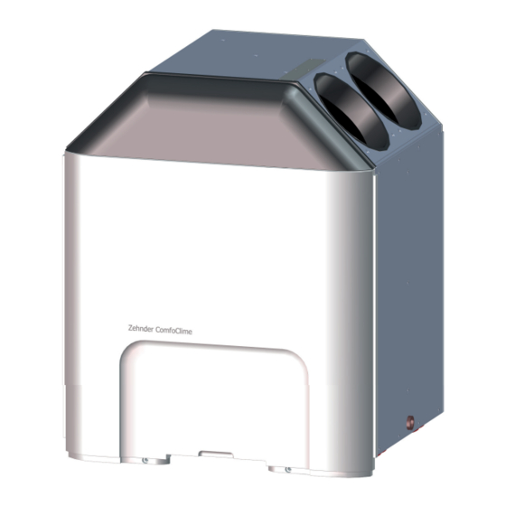
2 For the Installer 2.1 ComfoClime configuration and dimensions The standard ComfoClime configuration consists of: ■ 1 ComfoClime unit; ■ 1 cabled power supply plug; ■ 4 rubber ring seals; ■ 1 condensation drain cap; ■ 2 EPP standoffs; ■ 1 white plastic front cover; ■... -
Page 7: Technical Specifications
2.2 Technical specifications ComfoClime ComfoClime 24 ComfoClime 36 Performance Minimum airflow 200 m3/h 315 m3/h Maximum airflow 400 m3/h 600 m3/h Electrical connection details Maximum performance/power 1100 W 1100 W 230 V ± 10%, single phase, 230 V ± 10%, single phase,... -
Page 8: Installation Conditions
2.3 Installation conditions In order to determine whether the ComfoClime can be installed in a certain area, the following aspects must be taken into account: ■ The unit must be installed in a frost-free space; ■ The ventilation unit should be mounted on a floor stand, placed on a stable floor; ■... -
Page 9: Installation Of The Comfoclime
2.4 Installation of the ComfoClime 2.4.1 Transport and unpacking Contact your supplier immediately in case of damage or incomplete delivery. Take the necessary precautions when transporting and unpacking the ComfoClime unit. The permissible storage and transport temperature range is from +5°C to +50°C. Only transport it in an upright position. - Page 10 Check the identification plate to ensure that you have received the correct unit type ■ One plug for the unused condensation drain; ■ 2 EPP standoffs; ■ 4 Rubber seals. CAUTION! The supplier shall not be held liable for any damage, to things or people, caused by accidents due to a failure to comply with the instructions provided in this manual and in the following chapters.
-
Page 11: Configuration Of The Unit
2.5 Configuration of the unit Legend ACRONYM MEANING Outdoor air intake Indoor supply air Indoor air extraction Outdoor air expulsion Consider the following schemes to connect the ducts: CAUTION! The supplier shall not be held liable for any damage, to things or people, caused by accidents due to a failure to comply with the instructions provided in this manual and in the following chapters. - Page 12 Step Action Make sure that the ComfoAir Q is properly placed in its final position (see the ComfoAir Q installation manual) and not yet commissioned; Put the two EPP standoffs on the top part of ComfoAir Q as shown in the picture; Place the four rubber seal rings over the spigot openings and verifying the full insertion of them.
- Page 13 Step Action Fix the anti tilt plate (on top of the ComfoClime) firmly to the wall. To prevent vibrations being transmitted to the wall, ensure that the fall protection is not too rigidly fixed. Mount the plastic design front onto the unit. Check that the top of the plastic design front is properly matching the recesses and that it goes smoothly above the CAQ front plastic cover.
- Page 14 Step Action Connect the preferred drain, placed on the lateral side to the water drain system and plug the other up with the provided cap. NOTE: do not install a dry siphon: the overpressure in the unit could open the dry siphon guard and cause an air leakage.
-
Page 15: Installation Of Air Ducts
2.6.2 Installation of air ducts CAUTION! Do not connect the ComfoAir Q nor the ComfoClime to the power supply until the end of the complete installation and the mutual connection of the units is done. The unit must not be mounted/hung on the wall. -
Page 16: Wiring Diagram: Comfoclime
2.7 Wiring diagram: ComfoClime ComfoClime power cable (2 kW) already cabled in factory to be cabled on site LSF-SMT 350/04/180 * LSF-SMT 350/04/180 * power cable ComfoAir Q EN - 16... -
Page 17: Commissioning The Comfoclime
2.9 Commissioning the ComfoClime After installation, the ComfoClime must be commissioned. Always comply with the safety regulations, warnings, comments and instructions given in this document. Failure to comply with the safety regulations, instructions, warnings and comments may lead to personal injury or damage to the unit. Proceed with the unit activation according to the following steps: Step Action... -
Page 18: Troubleshooting
2.12 Troubleshooting This paragraph concerns issues related to the main unit. CAUTION! Never open the unit neither touch the internal components. Only authorized personnel should access the unit components. CAUTION! In case of malfunctioning such as weird noise, bad smell, water leakages, unplug immediately the power supply and call a Zehnder Authorised Representative. - Page 19 PAGE INTENTIONALLY LEFT BLANK 19 - EN...
- Page 20 Zehnder Group IT Via G. di Vittorio 6 41100 Campogalliano (MO), Italy...
Need help?
Do you have a question about the ComfoClime 24 and is the answer not in the manual?
Questions and answers