Table of Contents
Advertisement
Quick Links
Advertisement
Table of Contents

Subscribe to Our Youtube Channel
Related Manuals for VAT 62714-XE64-3 Series


Summary of Contents for VAT 62714-XE64-3 Series
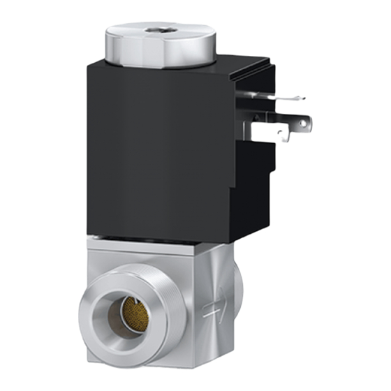
- Page 1 Control Valve 62714-XE64-...3 Operating Manual 1126117EA (2022-02)
-
Page 2: Product Identification
Product Identification In all communications with VAT please specify the information on the product nameplate. For convenient reference copy that information into the space provided below: made in Switzerland Fabrication No.: ..-..-../.. -
Page 3: Intended Use
Intended Use The 62714-XE64-..Control Valve is used in conjunction with the 627PM-16GV-000. Controller or another control device for controlling gas flows and thus maintaining a desired pressure in a vacuum system. It must not be used for controlling liquid gases. Functional Principle The 62714-XE64-.. -
Page 4: Symbols Used
Safety 1.1 Symbols Used DANGER Information on preventing any kind of physical injury. WARNING Information on preventing extensive equipment and environmental damage. Caution Information on correct handling or use. Disregard can lead to malfunctions or minor equipment damage. 1.2 Personnel Qualifications Skilled personnel All work described in this document may only be carried out by persons who have suitable technical training and the necessary... -
Page 5: General Safety Instructions
Communicate the safety instructions to all other users. 1.4 Liability and Warranty VAT assumes no liability and the warranty becomes null and void if the end-user or third parties • disregard the information in this document • use the product in a non-conforming manner •... -
Page 6: Technical Data
Technical Data Vacuum connection M14×1 Adapters (accessories) flange fitting DN 10 ISO-KF tube fitting OD ¼", OD 6 mm Installation angle any, preferably perpendicular Pressure range 1×10 … 2 bar (absolute) Tightness 1×10 mbar l/s Gas flow Note! Basic valves 62714-XE64-ABG3 100 sccm F.S. - Page 7 Dimensions [mm] 1126117EA (2022-02)
- Page 8 1126117EA (2022-02)
- Page 9 Flow rate curve Example of a flow rate curve (mean values 500 sccm F.S) at a ∆ pressure difference p = 1 bar Gas flow [sccm] Control valve open Control valve closed Current (solenoid coil) [mA] 1126117EA (2022-02)
- Page 10 Installation 3.1 Vacuum Connection Caution Caution: vacuum component Dirt and damages impair the function of the vacuum component. When handling vacuum components, take appro- priate measures to ensure cleanliness and prevent damages. Caution Caution: dirt sensitive area Touching the product or parts thereof with bare hands increases the desorption rate.
-
Page 11: Flange Connections
3.1.1 Flange Connections Remove the protective lids and mount two flange connections. 1126117EA (2022-02) - Page 12 Remove the protective lids and install the product to the vacuum system. DANGER DANGER: overpressure in the vacuum sys- tem >1 bar Injury caused by released parts and harm caused by escaping process gases can result if clamps are opened while the vacuum sys- tem is pressurized.
-
Page 13: Tube Connections
Clamping ring Seal with centering ring Watch the flow direction ISO-KF flange Protective lid connection Keep the protective lids. Check that the vacuum connections are leak tight. 3.1.2 Tube Connections Cut the tube to the required length and remove the burs. 1126117EA (2022-02) - Page 14 Slide the union nut and clamping rings over the tube. Remove the protective lid and insert the tube until the mechanical stop is reached. Watch the flow direction Keep the protective lids. 1126117EA (2022-02)
- Page 15 Slide the clamping rings up to the mechanical stop. Tighten the union nut with your fingers. 1126117EA (2022-02)
- Page 16 Tighten the union nut • initial installation by ¾ turns (stainless steel) • subsequent installation by ¼ turns (stainless steel) hold stationary Check that the vacuum connections are leak tight. 1126117EA (2022-02)
-
Page 17: Electrical Connection
3.2 Electrical Connection The polarity of the 24 VDC connection need not be taken into consideration. Before connecting or disconnecting the product, turn off the control system. Plug in the cable socket and secure it with the screw. 1126117EA (2022-02) -
Page 18: Operation
Operation The 62714-XE64-..Control Valve is ready for operation as soon as it has been installed. It will close or remain closed in the event of a power loss. De-installation Precondition Vacuum system vented. DANGER DANGER: contaminated parts Contaminated parts can be detrimental to health and environment. - Page 19 Caution Caution: vacuum component Dirt and damages impair the function of the vacuum component. When handling vacuum components, take appropriate measures to ensure cleanliness and prevent damages. Caution Caution: dirt sensitive area Touching the product or parts thereof with bare hands increases the desorption rate.
- Page 20 Procedure Unfasten the lock screw and unplug the cable socket. 1126117EA (2022-02)
- Page 21 Remove the product from the vacuum system and place the protective lids. Flange connections 1126117EA (2022-02)
- Page 22 Tube connections AF 17 1126117EA (2022-02)
-
Page 23: Maintenance & Repair
Maintenance / Repair Under clean operating conditions, the product requires no main- tenance. 6.1 Replacing the filter Precondition Valve de-installed. DANGER DANGER: contaminated parts Contaminated parts can be detrimental to health and environment. Before beginning to work, find out whether any parts are contaminated. - Page 24 Caution Caution: dirt sensitive area Touching the product or parts thereof with bare hands increases the desorption rate. Always wear clean, lint-free gloves and use clean tools when working in this area. Procedure Remove the filter from the inlet. Filter Circlip Protective lid...
- Page 25 Mount the filter. ø 6 mm Push in until circlip catches Circlip Filter 1126117EA (2022-02)
- Page 26 Accessories Ordering number Adapter M14×1 1 flange connection 579211 DN 10 KF 1 tube connection 579257 OD ¼" 1 tube connection 579292 OD 6 mm 627CV-89LC-000. Connection cable for 627CV-89LE-000. 627PM-16GV-000. 10 m 627CV-89LJ-000. Controller 15 m 627CV-89LK-000. 20 m 627CV-89LL-000.
-
Page 27: Returning The Product
Contaminated products (e.g. radioactive, toxic, caustic or biological hazard) can be detrimental to health and environment. Products returned to VAT should preferably be free of harmful substances. Adhere to the forwarding regulations of all involved countries and forwarding companies and enclose a duly completed declaration of contamination. - Page 28 9. Disposal DANGER DANGER: contaminated parts Contaminated parts can be detrimental to health and environment. Before beginning to work, find out whether any parts are contaminated. Adhere to the relevant re- gulations and take the necessary precautions when handling contaminated parts. WARNING WARNING: substances detrimental to the environment...
- Page 29 Series 627 This page has been left blank intentionally. 1126117EA (2022-02)
Need help?
Do you have a question about the 62714-XE64-3 Series and is the answer not in the manual?
Questions and answers