VAT 650 Series Installation, Operating, & Maintenance Instructions
Dn 200 (i.d. 8”), devicenet
Hide thumbs
Also See for 650 Series:
Table of Contents
Advertisement
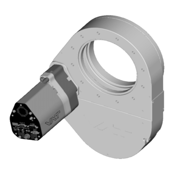
Pendulum control & isolation valve
with DeviceNet interface
This manual is valid for the valve ordering number(s):
65046-PHCQ-AFA1
configured with firmware 650P.1E.42 and 264420 (DeviceNet
The fabrication number is indicated on each product as per the label
below (or similar):
made in Switzerland
Fabrication No.:
650 . . – . . . . – . . . . / . . . .
A – . . . . . .
Explanation of symbols:
Read declaration carefully before you start any other
action!
Attention!
Loaded springs and/or air cushions are potential
hazards!
Disconnect electrical power and compressed air
lines. Do not touch parts under voltage!
Read these «Installation, Operating & Maintenance Instructions» and the enclosed «General
Safety Instructions» carefully before you start any other action!
Fehler! AutoText-Eintrag nicht definiert.
Installation, Operating & Maintenance Instructions
Series 650 DN 200 (I.D. 8"), DeviceNet
Fabrication number
®
)
Keep body parts and objects away from the valve
opening!
Hot surfaces; do not touch!
Wear gloves!
sample picture
288667EB
2011-12-23
1/74
Advertisement
Table of Contents

Related Manuals for VAT 650 Series


Summary of Contents for VAT 650 Series
- Page 1 Installation, Operating & Maintenance Instructions Series 650 DN 200 (I.D. 8”), DeviceNet Pendulum control & isolation valve with DeviceNet interface This manual is valid for the valve ordering number(s): 65046-PHCQ-AFA1 ® configured with firmware 650P.1E.42 and 264420 (DeviceNet The fabrication number is indicated on each product as per the label below (or similar): made in Switzerland Fabrication No.:...
- Page 2 VAT products. The VAT firmware contains a limited, time unlimited user license. The VAT firmware may not be used for purposes other than those intended nor is it permitted to make copies of the VAT firmware. In particular, it is strictly forbidden to give copies of the VAT firmware to other people.
-
Page 3: Table Of Contents
Installation, Operating & Maintenance Instructions Series 650 DN 200 (I.D. 8”), DeviceNet Contents: 1 Use of product ................................5 Technical data ..............................5 2 Installation................................. 7 Unpacking................................ 7 Installation into the system ..........................7 Tightening torque ............................. 9 2.3.1 Mounting with centering rings......................9 2.3.2 Mounting with O-ring in grooves ...................... - Page 4 Installation, Operating & Maintenance Instructions Series 650 DN 200 (I.D. 8”), DeviceNet Valve unit with seals and grease ........................71 Accessories ..............................72 7.3.1 Centering ring with Viton o-ring ......................72 8 Warranty ................................. 73 Fehler! AutoText-Eintrag nicht definiert. 288667EB 4/74 2011-12-23...
-
Page 5: Use Of Product
This product is a throttling pendulum valve with isolation functionality. It is intended to use for downstream pressure control applications. Use product for clean and dry indoor vacuum applications under the conditions indicated in chapter «Technical data» only! Other applications are only allowed with the written permission of VAT. Technical data Control and actuating unit Input voltage +24 VDC (±10%) @ 0.5 V pk-pk max. - Page 6 Installation, Operating & Maintenance Instructions Series 650 DN 200 (I.D. 8”), DeviceNet Valve unit 1 x 10E-6 mbar to 1.2 bar (abs) Pressure range at 20°C 1 x 10E-5 mbar l/s Leak rate to outside at 20°C 1 x 10E-4 mbar l/s Leak rate valve seat at 20°C Cycles until first service - Isolation cycles...
-
Page 7: Installation
Installation, Operating & Maintenance Instructions Series 650 DN 200 (I.D. 8”), DeviceNet Installation Unpacking As this valve is a heavy component you should lift it with adequate equipment to prevent any injury to humans. Valves DN200 (8”) and larger are equipped with attachment points (tapped holes). Add eyebolts to these attachment points for lifting. - Page 8 This valve has a double sealed rotary feedthrough and optionally an intermediate pumping port for the actuator shaft. This port (1/8“ ISO/NPT) could be connected to the vacuum line, see Figure 2 below. This valve may optionally be equipped with a heating device. Connect VAT heating device according to manual of respective heating device.
-
Page 9: Tightening Torque
Installation, Operating & Maintenance Instructions Series 650 DN 200 (I.D. 8”), DeviceNet Tightening torque Note: The torque values below are dependent on many factors, such as materials involved, surface quality, surface treatment, and lubrication. The torques below are valid if immersion depth of the mounting screws is at least once the thread diameter (min. 1d), and + µ... -
Page 10: Admissible Forces
For a combination of both forces (F and M) the values are invalid. Verify that the depth of the mounting screws is min. 1 x thread diameter. Please contact VAT for more information. Requirements to sensor connection To achieve fast and accurate pressure control a fast sensor response is required. -
Page 11: Electrical Connection
Installation, Operating & Maintenance Instructions Series 650 DN 200 (I.D. 8”), DeviceNet Electrical connection 2.6.1 Ground connection Recommendation for ground strap between controller and system (chassis) ∅ ∅ Material L (Length max.) B1 (min.) B2 (min.) d1 ( d2 ( copper tinned 200 mm 25 mm... -
Page 12: Sensor Supply Concepts
Installation, Operating & Maintenance Instructions Series 650 DN 200 (I.D. 8”), DeviceNet 2.6.2 Sensor supply concepts This valve has a built in sensor power supply (SPS). It supplies ±15 VDC. Concept: • External + 24 VDC supplied to POWER connector is converted into ±15 VDC by the valve internal SPS and supplied to SENSOR connector to supply ±15 VDC sensors. -
Page 13: Power And Sensor Connection (±15 Vdc Sensors) With Optional Sps Module
Installation, Operating & Maintenance Instructions Series 650 DN 200 (I.D. 8”), DeviceNet 2.6.3 Power and sensor connection (±15 VDC sensors) with optional SPS module [650 . . - . . A . - ../ 650 . . - . . C . - ..versions only] Pins 4 and 8 must be bridged for operation! An optional switch would allow for motor interlock to prevent valve from moving. -
Page 14: Devicenet® Connection
Installation, Operating & Maintenance Instructions Series 650 DN 200 (I.D. 8”), DeviceNet 2.6.4 DeviceNet® connection Connector type: Micro-style male (5 pin), connector is shown on panel refer to chapter «Installation into the system». At valve controller DeviceNet cable Name Wire color Description Drain Bare... -
Page 15: Logic I/O
Installation, Operating & Maintenance Instructions Series 650 DN 200 (I.D. 8”), DeviceNet 2.6.5 LOGIC I/O This interface allows for remote operation by means of a command set based on the DeviceNet protocol. In addition there is a digital input and a digital output. Digital input may only be operated by a switch. Active digital input has: higher priority than DeviceNet commands higher priority than Local commands... -
Page 16: Digital Input
The service port (connector: SERVICE) allows to connect the valve to a RS232 port of a computer. This requires a service cable and software from VAT. You can either use our freeware 'Control View', which can be downloaded from www.vatvalve.com or purchase our 'Control Performance Analyzer'. -
Page 17: Operation
Installation, Operating & Maintenance Instructions Series 650 DN 200 (I.D. 8”), DeviceNet Operation Valve opening Fingers and objects must be kept out of the valve opening and away from moving parts. Risk of injury. Do not connect the controller to power before the valve isn’t installed complete into the system. -
Page 18: Local Operation
Local operation means that the valve is operated via the service port using a computer or the Service Box 2. When using a computer, a service cable and a software from VAT are required. You can either download our freeware 'Control View' from or purchase our 'Control Performance Analyzer'. -
Page 19: Safety Mode
Installation, Operating & Maintenance Instructions Series 650 DN 200 (I.D. 8”), DeviceNet 3.1.3 Safety mode By means of an external switch (see connection diagrams «Electrical connection») the motor power supply can be interrupted. In this case the valve enters the ‘safety mode’. This motor interlock prevents the valve from moving (e.g. maintenance work). -
Page 20: Behavior In Case Of Power Failure
Valve open or in any intermediate position Display indicates F. *) Provided that battery pack of the VAT controller is charged. Charging time after power up is 2 minutes max.. All parameters are stored in a power fail save memory. Fehler! AutoText-Eintrag nicht definiert. -
Page 21: Display Information
Installation, Operating & Maintenance Instructions Series 650 DN 200 (I.D. 8”), DeviceNet Display information There is a 4 digit display located on the panel. It displays configuration, status and position information. For details see following tables. 1 2 3 4 Display Power up: Description... - Page 22 Installation, Operating & Maintenance Instructions Series 650 DN 200 (I.D. 8”), DeviceNet Operation: Description / Mode Digit 1 Digit 2 Digit 3 Digit 4 PRESSURE CONTROL mode POSITION CONTROL mode Valve closed 0 . . . 100 Valve open = valve position (%, 0 = closed / 100 = open) HOLD (position frozen) activated ZERO running LEARN running...
-
Page 23: Setup Procedure
Installation, Operating & Maintenance Instructions Series 650 DN 200 (I.D. 8”), DeviceNet Setup procedure To enable this valve for pressure control setup steps 1 to 6 must be performed. In case position control is required only it’s sufficient to perform steps 1 to 3. Setup step Description Turn on external + 24VDC power supply (and external ±15 VDC for sensor power... -
Page 24: Devicenet Configuration
® VAT offers valve-related but not general DeviceNet support. Contact us under: devicenet-support@vat.ch The node number is the device address and can be selected by two rotary switches which are on the panel. Set the most significant digit (MSD) with the middle switch and the least significant digit (LSD) with the left switch. - Page 25 Installation, Operating & Maintenance Instructions Series 650 DN 200 (I.D. 8”), DeviceNet Assembly object change procedure: Local operation: Remote operation: (‘Control View’, ‘Control Performance Analyzer’ or (Refer to chapter «Explicit messaging setup ‘Service Box 2‘) commands» for details) Select POLL CONNECTION OUTPUT assembly Select POLL CONNECTION INPUT...
-
Page 26: Logic I/O Configuration
Installation, Operating & Maintenance Instructions Series 650 DN 200 (I.D. 8”), DeviceNet 3.6.2 LOGIC I/O configuration Default configuration for LOGIC I/O is: Function Mode Input close valve non inverted enabled Digital input Function Mode Output close non inverted enabled Digital output The «LOGIC I/O»... -
Page 27: Valve And Sensor Configuration
Installation, Operating & Maintenance Instructions Series 650 DN 200 (I.D. 8”), DeviceNet 3.6.3 Valve and sensor configuration Basic valve configuration must be adapted according to application needs. • Definition of valve plate position (CLOSE or OPEN) after power up sequence. Default is ‘close‘. •... -
Page 28: Zero
Installation, Operating & Maintenance Instructions Series 650 DN 200 (I.D. 8”), DeviceNet 3.6.4 ZERO ZERO allows for the compensation of the sensor offset voltage. When ZERO is performed the current value at the sensor input is equated to pressure zero. In case of a 2 sensor system both sensor inputs will be adjusted. -
Page 29: Learn
Installation, Operating & Maintenance Instructions Series 650 DN 200 (I.D. 8”), DeviceNet 3.6.5 LEARN LEARN adapts the PID controller of the valve to the vacuum system and its operating conditions. LEARN must be executed only once during system setup. The LEARN routine determines the characteristic of the vacuum system. Based on this, the PID controller is able to run fast and accurate pressure control cycles. -
Page 30: Close Valve
Installation, Operating & Maintenance Instructions Series 650 DN 200 (I.D. 8”), DeviceNet Gasflow calculation for LEARN: Do not apply a different gasflow for learn than determined below. Otherwise pressure control performance may be insufficient. Choose the applicable formula depending on units you are familiar with. gasflow for learn [Pa m •... -
Page 31: Position Control
Installation, Operating & Maintenance Instructions Series 650 DN 200 (I.D. 8”), DeviceNet Position control The valve position is directly controlled according to the position setpoint. Local operation: Remote operation: (‘Control View’, ‘Control Performance Analyzer’ or (Refer to chapter «Explicit messaging control ‘Service Box 2‘) commands»... -
Page 32: Pressure Control Operation With 2 Sensors
Installation, Operating & Maintenance Instructions Series 650 DN 200 (I.D. 8”), DeviceNet 3.10.1 Pressure control operation with 2 sensors [applicable with 650 . . - . . . Q - ..version only] If 2 sensor operation is enabled, changeover between the sensors is done automatically during pressure control. For configuration refer to chapter «Setup procedure». -
Page 33: Tuning Of Control Performance
Pressure / flow / gas conditions to be controlled • Chamber volume • Pumping speed (l/s) and pump type (e.g. turbo pump) • System description • Problem description Send diagnostic file with and all required information to tuning-support@vat.ch Fehler! AutoText-Eintrag nicht definiert. 288667EB 33/74 2011-12-23... - Page 34 Installation, Operating & Maintenance Instructions Series 650 DN 200 (I.D. 8”), DeviceNet 3.10.2.1 Gain factor adjustment The gain factor effects: • Stability • Response time Default value is 1. Adjustment range is from 0.0001 to 7.5. Higher gain results in: faster response higher over- / undershoot of pressure Lower gain results in:...
- Page 35 Installation, Operating & Maintenance Instructions Series 650 DN 200 (I.D. 8”), DeviceNet 3.10.2.3 Setpoint ramp adjustment Setpoint ramp effects: • Undershoot of pressure • Response time Default value for Setpoint Ramp is 1. Adjustment range for Setpoint Ramp is from 0 to 10 s. This parameter defines the time that is used to decrease / raise pressure between 2 setpoints.
- Page 36 Installation, Operating & Maintenance Instructions Series 650 DN 200 (I.D. 8”), DeviceNet 3.10.2.4 Valve speed adjustment Valve speed effects: • Response time Default value is 1000. Adjustment range is from 1 to 1000. This parameter effects valve plate actuating speed. Speed adjustment is effective for PRESSURE CONTROL and POSITION CONTROL.
-
Page 37: Interface
Installation, Operating & Maintenance Instructions Series 650 DN 200 (I.D. 8”), DeviceNet ® 3.11 DeviceNet interface 3.11.1 Assembly objects Note: Factory default assemblies are: Input assembly 3 / Output assembly 8 Number Type Composition [number of data bytes] EXCEPTION STATUS Input PRESSURE [2] or [4]... -
Page 38: Assembly Object Bit Map
Installation, Operating & Maintenance Instructions Series 650 DN 200 (I.D. 8”), DeviceNet 3.11.2 Assembly object bit map This is an example based on output assembly 8 and input assembly 3 to illustrate bit map. DATA TYPE in this example is signed integer. 3.11.2.1 Output assembly Assembly... - Page 39 Installation, Operating & Maintenance Instructions Series 650 DN 200 (I.D. 8”), DeviceNet 3.11.2.2 Input assembly Instance Type Byte Bit7 Bit6 Bit5 Bit4 Bit3 Bit2 Bit1 Bit0 EXCEPTION STATUS PRESSURE low byte Input PRESSURE high byte POSITION low byte POSITION high byte EXCEPTION STATUS will respond with one out of below selections, see also «Explicit messaging inquiry commands».
-
Page 40: Explicit Messaging Control Commands
Installation, Operating & Maintenance Instructions Series 650 DN 200 (I.D. 8”), DeviceNet 3.11.3 Explicit messaging control commands Service Service Command Service Code Class ID Instance ID Attribute ID data length ® data field (DeviceNet term (number of bytes) if deviant) Description This command changes the valve to executing state. - Page 41 Installation, Operating & Maintenance Instructions Series 650 DN 200 (I.D. 8”), DeviceNet Service Service Command Service Code Class ID Instance ID Attribute ID data length ® data field (DeviceNet term (number of bytes) if deviant) Description 2 or 4 2 or 4 POSITION SETPOINT position setpoint according to selected DATA TYPE, 0 (closed) …...
-
Page 42: Explicit Messaging Inquiry Commands
Installation, Operating & Maintenance Instructions Series 650 DN 200 (I.D. 8”), DeviceNet 3.11.4 Explicit messaging inquiry commands Service Service Command Service Code Class ID Instance ID Attribute ID data length ® data field (DeviceNet term (number of bytes) if deviant) Description VALVE CLOSED This command returns:... - Page 43 Installation, Operating & Maintenance Instructions Series 650 DN 200 (I.D. 8”), DeviceNet Example of PRESSURE and SENSOR READING allocation: High range sensor 1 Torr PRESSURE SENSOR 1 READING 0 – 10’000 0 – 10’000 Low range sensor 100 mTorr SENSOR 2 READING 0 –...
- Page 44 Installation, Operating & Maintenance Instructions Series 650 DN 200 (I.D. 8”), DeviceNet Service Service Command Service Code Class ID Instance ID Attribute ID data length ® data field (DeviceNet term (number of bytes) if deviant) Description This command returns the status of the LEARN procedure. The status is binary coded. Explanation: (LSB) 0 0 = LEARN not running...
- Page 45 Installation, Operating & Maintenance Instructions Series 650 DN 200 (I.D. 8”), DeviceNet Service data length Service Command Service Code Class ID Instance ID Attribute ID (number of data field (DeviceNet® term bytes) if deviant) Description self test idle self test exception DEVICE STATUS 1 executing abort...
- Page 46 Installation, Operating & Maintenance Instructions Series 650 DN 200 (I.D. 8”), DeviceNet Service Service Command Service Code Class ID Instance ID Attribute ID data length ® data field (DeviceNet term (number of bytes) if deviant) Description Table with EXCEPTION DETAIL ALARM resp. EXCEPTION DETAIL WARNING bits. Exception / Failure / Error (except for detail size bytes) Data Bit 7...
- Page 47 Installation, Operating & Maintenance Instructions Series 650 DN 200 (I.D. 8”), DeviceNet Service data length Service Command Service Code Class ID Instance ID Attribute ID (number of data field (DeviceNet® term bytes) if deviant) Description THROTTLE CYCLE This command returns the number of throttle cycles. Data type is unsigned long integer. A COUNTER movement from max.
-
Page 48: Explicit Messaging Setup Commands
Installation, Operating & Maintenance Instructions Series 650 DN 200 (I.D. 8”), DeviceNet 3.11.5 Explicit messaging setup commands Service Service Command Service Code Class ID Instance ID Attribute ID data length ® data field (DeviceNet term (number of bytes) if deviant) Description signed integer DATA TYPE... - Page 49 Installation, Operating & Maintenance Instructions Series 650 DN 200 (I.D. 8”), DeviceNet Command Service Service ® Service Code Class ID Instance ID Attribute ID (DeviceNet term data length data field if deviant) (number of bytes) CHANGE OF STATE / input assembly object number (3, 4, 5, 13, 14, 100, 101) CYCLING INPUT This command configures resp.
- Page 50 Installation, Operating & Maintenance Instructions Series 650 DN 200 (I.D. 8”), DeviceNet Command Service Service ® Service Code Class ID Instance ID Attribute ID (DeviceNet term data length data field if deviant) (number of bytes) no sensor 1 sensor operation (sensor 1 input) 2 sensor operation with automatic changeover (low range = sensor 2 input, high range = sensor 1 input) 1 sensor operation (sensor 2 input)
- Page 51 Installation, Operating & Maintenance Instructions Series 650 DN 200 (I.D. 8”), DeviceNet Command Service Service ® Service Code Class ID Instance ID Attribute ID (DeviceNet term data length data field if deviant) (number of bytes) 2 or 4 LEARN learn pressure limit according to selected DATA TYPE, PRESSURE LIMIT nominal pressure range is 0 …...
- Page 52 Installation, Operating & Maintenance Instructions Series 650 DN 200 (I.D. 8”), DeviceNet Command Service Service ® Service Code Class ID Instance ID Attribute ID (DeviceNet term data length data field if deviant) (number of bytes) 0 = 0.10, 1 = 0.13, 2 = 0.18, 3 = 0.23, 4 = 0.32, 5 = 0.42, 6 = 0.56 PID CONTROLLER 7 = 0.75, 8 = 1.00, 9 = 1.33, 10 = 1.78, 11 = 2.37, 12 = 3.16, 13 = 4.22 GAIN FACTOR...
-
Page 53: Trouble Shooting
Installation, Operating & Maintenance Instructions Series 650 DN 200 (I.D. 8”), DeviceNet Trouble shooting Failure Check Action No dots lighted on display - 24 V power supply ok? - Connect valve to power supply according to «Electrical connection» and make sure that power supply is working. - Page 54 Exhaust « AIRx » output - Contact your local VAT service centre for support. - No compressed air at output exhaust 1)Priority of pin 14 is higher than pin 13. If pin 14 is connected to ground after pin 13 the valve will close.
- Page 55 - Noise on sensor signal? - Make sure a shielded sensor cable is used. If you need any further information, please contact one of our service centers. You can find the addresses on our website: http://www.vat.ch Fehler! AutoText-Eintrag nicht definiert. 288667EB...
-
Page 56: Maintenance & Repairs
Contamination from the process may influence the function and requires more frequent maintenance. Before carrying out any maintenance or repairs, please contact VAT. It has to be individually decided whether the maintenance/repair can be performed by the customer or has to be carried out by VAT. The fabrication number on the valve made in Switzerland Fabrication No.:... -
Page 57: Maintenance Procedures
A critical factor influencing the maintenance period is the lifetime of the vacuum grease, being limited under increased temperature. In this case grease will separate to PTFE and oil. The oil may flow and contaminate the valve parts. VAT can give the following recommendations for preventive maintenance: heated ≤ 80°C *) unheated *) heated >... - Page 58 Installation, Operating & Maintenance Instructions Series 650 DN 200 (I.D. 8”), DeviceNet Note: Electrical power and compressed air is required to perform steps 2 to 9 during disassembly respectively 9 to 2 during assembly. D e s c r i p t i o n Required tool Vent both valve chambers.
- Page 59 Soft tool in an ultrasonic bath. (o-ring remover) 11. Clean out valve body with alcohol. gate seal VAT cleaning tool Use an appropriate non metal tool for valve body with a cloth to enter valve body. (Part No. see Do not enter valve body with hands!
- Page 60 Installation, Operating & Maintenance Instructions Series 650 DN 200 (I.D. 8”), DeviceNet D e s c r i p t i o n Required tool • CV software 18. Release the valve from safety mode. Refer to «Safety mode» for details 19.
- Page 61 Installation, Operating & Maintenance Instructions Series 650 DN 200 (I.D. 8”), DeviceNet D e s c r i p t i o n Required tool • Soft tool (o-ring remover) 24. Remove actuator shaft seals carefully with a soft tool. 25.
- Page 62 Installation, Operating & Maintenance Instructions Series 650 DN 200 (I.D. 8”), DeviceNet D e s c r i p t i o n Required tool 35. Turn on power of controller. Note: valve moves to close position. open end wrench 36.
- Page 63 Installation, Operating & Maintenance Instructions Series 650 DN 200 (I.D. 8”), DeviceNet D e s c r i p t i o n Required tool Lint-and dust- free towel a little 39. Clean the valve sealing surface soaked with isopropyl alcohol Lint-and dust- 40.
-
Page 64: Option Board
Installation, Operating & Maintenance Instructions Series 650 DN 200 (I.D. 8”), DeviceNet Option board The option board may or may not be equipped in your valve depending on the order. Refer to page 1 of this manual to check valve version. This board includes the optional modules for the valve which are: •... -
Page 65: Retrofit / Replacement Procedure
Installation, Operating & Maintenance Instructions Series 650 DN 200 (I.D. 8”), DeviceNet 5.2.2 Retrofit / replacement procedure ESD Precaution! All work on the control and actuating unit has to be done under ESD protected environment to prevent electronic components from damage! Top view on control and actuating unit with panel removed: Master board Option board... - Page 66 Installation, Operating & Maintenance Instructions Series 650 DN 200 (I.D. 8”), DeviceNet Description Required tool Write down the «NODE ADDRESS» and «DATA RATE» in case of Interface board Ballpoint replacement. Remove female screw locks from POWER Open end wrench 4.5 mm and SENSOR connectors.
- Page 67 Installation, Operating & Maintenance Instructions Series 650 DN 200 (I.D. 8”), DeviceNet Description Required tool Lift the panel carefully. Pull out the option board a little. Push the connector release (1) a little down and disconnect fan cable (2) from option board.
- Page 68 Installation, Operating & Maintenance Instructions Series 650 DN 200 (I.D. 8”), DeviceNet Description Required tool 10. Remove or replace option board. 11. Insert all board in reverse order as disassembled at correct positions (see steps 10 to 8). 12. Reconnect fan cable to option board (see steps 7 to 6).
-
Page 69: Drawing
Installation, Operating & Maintenance Instructions Series 650 DN 200 (I.D. 8”), DeviceNet Drawing Bonnet seal Body seal Plate seal Rotary feedthrough seals Shaft feedthrough seals Pendulum plate Sealing ring Actuator Control unit Fehler! AutoText-Eintrag nicht definiert. 288667EB 69/74 2011-12-23... -
Page 70: Spare Parts
Installation, Operating & Maintenance Instructions Series 650 DN 200 (I.D. 8”), DeviceNet Spare parts Please specify the fabrication number of the valve (see yellow label on valve) when ordering spare parts. This is to ensure that the appropriate spare parts are supplied. Control unit Item Description... -
Page 71: Valve Unit With Seals And Grease
N-7121-112 Shaft (e.g. Viton®)) feedthrough seals vacuum (FKM N-7121-112 (e.g. Viton®)) Pendulum plate 200500 Sealing ring 202046 Actuator 342943 Note: Use only spare parts manufactured by VAT to assure safe and reliable operation! Fehler! AutoText-Eintrag nicht definiert. 288667EB 71/74 2011-12-23... -
Page 72: Accessories
Installation, Operating & Maintenance Instructions Series 650 DN 200 (I.D. 8”), DeviceNet Accessories Item Description Part number 24 VDC power supply unit 249775 (input: 100 – 240 VAC) ‘Control Performance Analyzer’ ® package for Windows consisting 600SP-99LB-000 of software and cable ‘Control View’... -
Page 73: Warranty
(including any delay in or failure to deliver), packaging, storage or use of any product sold or delivered by VAT shall fail to conform to the... - Page 74 Installation, Operating & Maintenance Instructions Series 650 DN 200 (I.D. 8”), DeviceNet Fehler! AutoText-Eintrag nicht definiert. 288667EB 74/74 2011-12-23...
Need help?
Do you have a question about the 650 Series and is the answer not in the manual?
Questions and answers