VAT 642 Series Installation, Operating, & Maintenance Instructions
Control gate valve with rs232 interface, dn 63- 400 mm (i.d. 2.5“ - 16")
Hide thumbs
Also See for 642 Series:
Table of Contents
Advertisement
Quick Links
Installation, Operating &
Maintenance Instructions
Control gate valve
with RS232 interface
Series 642
DN 63- 400 mm (I.D. 2.5" - 16")
This manual is valid for the valve ordering number(s):
642 . . - . .TG - . . . .
642 . . - . .TH - . . . .
642 . . - . .VG - . . . .
642 . . - . .VH - . . . .
642 . . - . .UG - . . . .
642 . . - . .UH - . . . .
642 . . - . .WG - . . . .
642 . . - . .WH - . . . .
642 . . - . .TV - . . . .
642 . . - . .TW - . . . .
642 . . - . .VV - . . . .
642 . . - . .VW - . . . .
642 . . - . .UV - . . . .
642 . . - . .UW - . . . .
642 . . - . .WV - . . . .
642 . . - . .WW - . . . .
642 . . - . .
GS
642 . . - . .
HS
SPS = Sensor Power Supply
Master configured with firmware:
Slave configured with firmware:
Sample picture
742280ED
(Master / 1 sensor input)
(Master / 2 sensor inputs)
(Master / 1 sensor input / ±15V SPS)
(Master / 2 sensor inputs / ±15V SPS)
(Master / 1 sensor input / PFO)
(Master / 2 sensor inputs / PFO)
(Master / 1 sensor input / ±15V SPS / PFO)
(Master / 2 sensor inputs / ±15V SPS / PFO)
(Master / 1 sensor input / analog outputs)
(Master / 2 sensor inputs / analog outputs)
(Master / 1 sensor input / analog outputs / ±15V SPS)
(Master / 2 sensor inputs / analog outputs / ±15V SPS)
(Master / 1 sensor input / analog outputs / PFO)
(Master / 2 sensor inputs / analog outputs / PFO)
(Master / 1 sensor input / analog outputs / ±15V SPS / PFO)
(Master / 2 sensor inputs / analog outputs / ±15V SPS / PFO)
- . . . .
(Slave)
- . . . .
(Slave / PFO)
PFO = Power Failure Option
600P.1G.00.07...08
600P.1G.00.07...08
Edition 2017-11-24
Advertisement
Table of Contents

Related Manuals for VAT 642 Series


Summary of Contents for VAT 642 Series
- Page 1 Installation, Operating & Maintenance Instructions Control gate valve with RS232 interface Series 642 DN 63- 400 mm (I.D. 2.5“ - 16") This manual is valid for the valve ordering number(s): 642 . . - . .TG - ..(Master / 1 sensor input) 642 .
- Page 2 The VAT firmware may not be used for purposes other than those intended nor is it permitted to make copies of the VAT firmware. In particular, it is strictly forbidden to give copies of the VAT firmware to other people.
-
Page 3: Table Of Contents
Series 642 Contents Description of product ................ 5 Identification of product ....................5 Use of product ......................... 5 Used abbreviations ......................5 Related documents......................5 Important information....................... 5 Technical data ......................... 6 1.6.1 Control and actuating unit ................. 6 1.6.2 Valve unit ...................... - Page 4 Series 642 RS232 interface commands ..................56 4.8.1 RS232 command syntax ................. 56 4.8.2 Control commands ..................56 4.8.3 Inquiry commands ................... 57 4.8.4 Setup commands .................... 65 4.8.5 Pressure control algorithem ................75 4.8.6 Error messages ....................80 Operation ................... 81 Normal operation ......................
-
Page 5: Description Of Product
This product is a control gate valve with isolation functionality. It is intended to use for downstream pressure control applications. Use product for clean and dry vacuum applications only. Other applications are only allowed with the written permission of VAT. Used abbreviations Abbreviation... -
Page 6: Technical Data
DESCRIPTION OF PRODUCT Series 642 Technical data 1.6.1 Control and actuating unit Description Power input (α) +24 VDC (±10%) @ 0.5 V pk- [connector: POWER] pk max. [642 . . - . . A . - ../ 642 . . - . . G . - ..] 50 W max. - Page 7 Series 642 DESCRIPTION OF PRODUCT Control and actuating unit (continuation) Sensor input Signal input voltage 0-10 VDC / Ri>100 kΩ [connector: SENSOR] ADC resolution 0.23 mV Sampling time 10 ms Digital inputs ±24 VDC max. [connector: INTERFACE] Digital outputs [connector: INTERFACE] Input voltage 70 VDC or 70 V peak max.
-
Page 8: Valve Unit
DESCRIPTION OF PRODUCT Series 642 1.6.2 Valve unit Description Pressure range at 20°C (unheated on delivery) • 1 × 10E-8 mbar to 2.0 bar (abs) DN63…200 • 1 × 10E-8 mbar to 1.2 bar (abs) DN250…400 1 × 10E-9 mbar ls Leak rate to outside / seat at 20°C (unheated on delivery) Differential pressure on the gate •... -
Page 9: Safety
Series 642 SAFETY Safety Compulsory reading material Read this chapter prior to performing any work with or on the product. It contains important information that is significant for your own personal safety. This chapter must have been read and understood by all persons who perform any kind of work with or on the product during any stage of its serviceable life. -
Page 10: Personnel Qualifications
SAFETY Series 642 Personnel qualifications WARNING Unqualified personnel Inappropriate handling may cause serious injury or property damage. Only qualified personnel are allowed to carry out the described work. Safety labels Label Part No. Location on valve On protective foil covering of T-9001-156 valve opening 10/119... -
Page 11: Design And Function
Actuation is performed with a stepper motor and controller. The stepper motor/controller version ensures accurate pressure control due to exact gate positioning. For leak tight closing the VATLOCK principle is applied. For details refer to VAT catalog. 742280ED Edition 2017-11-24... -
Page 12: Pressure Control System Overview And Function
DESIGN AND FUNCTION Series 642 3.2.1 Pressure control system overview and function Vacuum pressures are always absolute pressures unless explicitly specified as pressure differences. Valve Process chamber Gas inlet Pressure sensor(s) Sensor cable Controller and actuator Seff Cable to remote control unit Cable to power supply HV Pump Q / p... -
Page 13: Principle Of A Pressure Control System
Series 642 DESIGN AND FUNCTION 3.2.1.1 Way of operation The controller compares the actual pressure in the process chamber given by the pressure sensor with the preset pressure. The controller uses the difference between actual and set pressure to calculate the correct position of the control valve. The controller drives the control valve into the correct position and the actual pressure again equals the set pressure. -
Page 14: Installation
Make sure that the supplied products are in accordance with your order. • Inspect the quality of the supplied products visually. If it does not meet your requirements, please contact VAT immediately. • Store the original packaging material. It may be useful if products must be returned to VAT. -
Page 15: Installation Into The System
Series 642 INSTALLATION Installation into the system WARNING Valve opening Risk of serious injury. Human body parts must be kept out of the valve opening and away from moving parts. Do not connect the controller to power before the valve is installed complete into the system. -
Page 16: Installation Space Condition
INSTALLATION Series 642 4.2.1 Installation space condition Install the valve with integrated controller with space for dismantling and air circulation as shown in figure below. (sample picture) Overview table: DN to required distance (d) for maintenance. 80 / 100 320 / 350 16/119 Edition 2017-11-24 742280ED... -
Page 17: Connection Overview
Series 642 INSTALLATION 4.2.2 Connection overview System: Valve Pressure sensor(s) Sensor cable(s) Cable to RS232 remote control unit Cable to power supply Slave Master Link cable [6] Link cable [6] Link to next Slave Actuator Controller 4.2.3 Installation procedure 1. Install valve [1] into the vacuum system, with valve seat side to process chamber. The valve seat side is indicated by the symbol "∆"... -
Page 18: Tightening Torque
Refer also to «Safety mode». 10. This valve may optionally be equipped with a heating device. Connect VAT heating device according to manual of respective heating device. -
Page 19: Mounting With Centering Rings
Series 642 INSTALLATION high. Therefore for other friction coefficients the torque needs to be adapted. Please review design guidelines for Helicoil-Screw connections and make sure that screws in Tight use are capable to withstand applied torques, are appropriate for the application and are not too long. -
Page 20: Mounting With O-Ring In Grooves
INSTALLATION Series 642 4.3.2 Mounting with O-ring in grooves max. torque t max. torque Max. hole depth [d] (Nm) (lbs . ft) (mm) inch ISO-F ASA-LP ISO-F ASA-LP ISO-F ASA-LP 20/119 Edition 2017-11-24 742280ED... -
Page 21: Admissible Forces
2½ 1960 1960 2450 2940 2940 3430 3920 3920 7840 1760 In case of both kind of forces are occurring («FA» und «M»), the above shown values are invalid. Please contact VAT in this case. 742280ED Edition 2017-11-24 21/119... -
Page 22: Requirements To Sensor Connection
INSTALLATION Series 642 4.4.1 Requirements to sensor connection To achieve fast and accurate pressure control a fast sensor response is required. Sensor response time: < 50ms. The sensor is normally connected to the chamber by a pipe. To maintain that the response time is not degraded by this connection it needs to meet the following requirements: •... -
Page 23: Ground Connection
Series 642 INSTALLATION 4.5.1 Ground connection Recommendation for ground strap between controller ground and system chassis. ∅ ∅ Material L (Length max.) B1 (min.) B2 (min.) d1 ( d2 ( copper tinned 200 mm 25 mm 25 mm 4.5 mm customized Chassis (PE) (Protective Earth) -
Page 24: 4.5.2 Sensor Supply Concepts
INSTALLATION Series 642 4.5.2 Sensor supply concepts This valve offers 3 alternative concepts to supply the sensor(s) with power. This depends on the sensor type and valve version that is used. This valve is available with an optional sensor power supply module (SPS) that converts ±15 VDC from the 24 VDC. -
Page 25: Power And Sensor Connection (+24 Vdc Sensors)
Series 642 INSTALLATION 4.5.3 Power and sensor connection (+24 VDC sensors) [642 . . - . . G . - ../ 642 . . - . . H . - ..versions recommended] 4.5.3.1 Sensor power wiring via controller Pins 4 and 8 must be bridged for operation. - Page 26 INSTALLATION Series 642 4.5.3.2 Sensor power wiring external Pins 4 and 8 must be bridged for operation. An optional switch would allow for motor interlock to prevent valve from moving. Low range sensor may be connected to sensor 1 or sensor 2 input.
-
Page 27: 4.5.4 Power And Sensor Connection (±15 Vdc Sensors) Without Opt. Sps Module
Series 642 INSTALLATION 4.5.4 Power and sensor connection (±15 VDC sensors) without opt. SPS module [642 . . - . . G . - ../ 642 . . - . . H . - ..versions only] 4.5.4.1 Sensor power wiring via controller Pins 4 and 8 must be bridged for operation. - Page 28 INSTALLATION Series 642 4.5.4.2 Sensor power wiring external Pins 4 and 8 must be bridged for operation. An optional switch would allow for motor interlock to prevent valve from moving. Low range sensor may be connected to sensor 1 or sensor 2 input.
-
Page 29: 4.5.5 Power And Sensor Connection (±15 Vdc Sensors) With Opt. Sps Module
Series 642 INSTALLATION 4.5.5 Power and sensor connection (±15 VDC sensors) with opt. SPS module [642 . . - . . A . - ../ 642 . . - . . C . - ..versions only] Pins 4 and 8 must be bridged for operation. -
Page 30: Power Connection For Slave Valve Only
You can use our Software (freeware) 'Control Performance Analyzer' which can be downloaded from: http://www.vatvalve.com/customer-service/informations-and-downloads/control-performance-analyzer. Alternatively the VAT Service Box2 can be connected to the service port for setup and local operation. The service port is not galvanic isolated. Therefore we recommend using this only for setup, testing and maintenance and not for permanent control. -
Page 31: Valve Cluster Connection
Series 642 INSTALLATION 4.5.8 Valve cluster connection The valve cluster uses a two wire bus for the inter communication between the Master and the Slave valves. The valves are connected in a daisy chain and the bus must be terminated on both sides by a 120Ω... - Page 32 INSTALLATION Series 642 4.5.8.1 Link adapter Link adapter 2x RJ45 jack (female) 1x Service port Inside view with terminating resistor Factory default setting Terminating resistor OFF 32/119 Edition 2017-11-24 742280ED...
- Page 33 Data Data not used not used not used VAT recommends a cable with the following specification: • Standard patch cable • Category 5 or higher • Double ended with shielded RJ45 connector • Straight through connection 1:1...
-
Page 34: Functions And Wiring
INSTALLATION Series 642 4.5.9 Functions and Wiring This interface allows for remote operation by means of a command set based on the RS232 protocol. In addition there are 2 digital inputs and 2 digital outputs. Digital inputs may be operated either by switches or by voltage sources. - Page 35 Series 642 INSTALLATION b) Configuration with voltage source for digital inputs: Do not connect other pins than indicated in the schematics above! Use only screws with 4-40UNC thread for fastening the DB-25 connector! 742280ED Edition 2017-11-24 35/119...
- Page 36 INSTALLATION Series 642 4.5.9.1 Digital inputs Function Signal type Description Priority This function will close the valve. Valve will be in interlock mode as long as function is activated. After deactivation of function it will remain effective until - OPEN valve digital input is active - converse RS232 control command have been received Digital The function is activated when optocoupler is ‘on’...
-
Page 37: Initial Operation
• For ease setup (in Local mode) of ‘Interface’, ‘Valve’, ‘Sensor’, ‘Senor ZERO’, ‘LEARN’ and ‘PRESSURE CONTROL COFIGURATION’ it is possible to use the CPA 3.0, The free download is available on the VAT homepage: http://www.vatvalve.com/customer-service/informations-and-downloads/control- performance-analyzer 742280ED... -
Page 38: Interface Configuration
INSTALLATION Series 642 4.6.2 Interface configuration Interface configuration must be adapted according to application needs (Master valve only). • Functionality of digital interlock inputs CLOSE VALVE and OPEN VALVE. These may be configured as ‘not inverted‘, ‘inverted‘ or ‘disabled‘. Default is ‘not inverted‘. Refer also to «Digital inputs». •... - Page 39 Series 642 INSTALLATION 4.6.3.1 Address setting via graphical interface (SETUP -> CLUSTER) Master valve Slave valve 742280ED Edition 2017-11-24 39/119...
- Page 40 INSTALLATION Series 642 4.6.3.2 Address setting via Terminal function Command: code description data range s:10 Command header none Cluster address high byte in hexadecimal code 0…F Cluster address low byte in hexadecimal code 0…F Number of valves high byte in hexadecimal code (Master only) 0…F Number of valves low byte in hexadecimal code (Master only) 0…F...
-
Page 41: Valve Configuration
Series 642 INSTALLATION Address allocation: Each valve connected to the valve cluster system must have its unique cluster address. It is possible to address 255 cluster valves. The address allocation is as follows: Master valve: Slave valves: 01 – FE If there only one Slave valve the adress must be: 01. -
Page 42: Zero
INSTALLATION Series 642 4.6.6 ZERO This function is available on the (Master valve only). ZERO allows for the compensation of the sensor offset voltage. When ZERO is performed the current value at the sensor input is equated to pressure zero. In case of a 2 sensor system both sensor inputs will be adjusted. -
Page 43: Learn (Adaptive)
Series 642 INSTALLATION 4.6.7 LEARN (adaptive) LEARN adapts the PID controller of the valve to the vacuum system and its operating conditions. LEARN must be executed only once during system setup (Master valve only). The LEARN routine determines the characteristic of the vacuum system. Based on this, the PID controller is able to run fast and accurate pressure control cycles. - Page 44 INSTALLATION Series 642 Gasflow calculation for LEARN: Do not apply a different gasflow for learn than determined below. Otherwise pressure control performance may be insufficient. Required pressure / flow regime must be known to calculate the most suitable learn gas flow for a specific application. 1.
-
Page 45: Tuning Of Control Performance
Series 642 INSTALLATION Tuning of control performance • Tuning of pressure control performance with adaptive control, refer to chapter: 4.7.1 Tuning of control performance with adaptive pressure controller • Tuning of pressure control performance with PI control, refer to chapter: 4.7.2 Tuning of control performance with fixed PI pressure controller •... - Page 46 INSTALLATION Series 642 4.7.1.1 Gain factor adjustment The gain factor effects: Stability, Response time Adjustment range is from 0.0001 to 7.5. • Higher gain results in: faster response / higher over- / undershoot of pressure • Lower gain results in: slower response/ lower over- / undershoot of pressure Adjustment procedure: Start with gain factor 1.0 Open valve...
- Page 47 Series 642 INSTALLATION 4.7.1.2 Sensor delay adjustment Sensor delay adjustment effects: Stability Adjustment range is from 0 to 1.0s. Pipes and orifices for sensor attachment delay response time and so badly impact pressure control stability. By adapting this parameter to the approximate delay time stability problems can be reduced. But control response time will be slowed down by this measure.
- Page 48 INSTALLATION Series 642 4.7.1.3 Setpoint ramp adjustment Setpoint ramp effects: Undershoot of pressure, Response time Adjustment range for Setpoint Ramp is from 0 to 10 s. This parameter defines the time that is used to decrease / raise pressure between 2 setpoints. Especially in pressure decrease situations at low flows pressure response can be improved much by adapting setpoint ramp time.
- Page 49 Series 642 INSTALLATION Local operation: Remote operation: (‘Control Performance Analyzer’ or ‘Service Box 2‘) (Refer to chapter «Pressure control algorithm» > «Adaptive control algorithm» for details) With CPA: • Do the ‘Ramp Time’ and ‘Ramp Mode’ adjustment in menu ‘Pressure Control’ / ‘Setup’...
- Page 50 Pressure / flow / gas conditions to be controlled • Chamber volume • Pumping speed (l/s) and pump type (e.g. turbo pump) • System description • Problem description Send diagnostic file with and all required information to tuning-support@vat.ch 50/119 Edition 2017-11-24 742280ED...
-
Page 51: Tuning Of Control Performance With Fixed Pi Pressure Controller
Series 642 INSTALLATION 4.7.2 Tuning of control performance with fixed PI pressure controller 4.7.2.1 Optimizing P gain and I gain This valve may be used for downstream or upstream pressure control depending on configuration. The PI parameters of the pressure controller require correct adjustment. These parameters must be set once during system setup and are stored in the device memory which is power fail save. - Page 52 INSTALLATION Series 642 Optimizing P gain While optimizing P gain, the gas flow determined above has to be constant all the time. Start optimization with P gain set to 1.0 and I gain set to 0.0. Set chamber pressure to SP2, wait until the pressure is stable. Set pressure to SP1. If the transition from SP2 to SP1 results in a significant pressure over shoot or even does not stabilize at all, the P gain is too high.
- Page 53 Pressure / flow / gas conditions to be controlled • Chamber volume • Pumping speed (l/s) and pump type (e.g. turbo pump) • System description • Problem description Send diagnostic file with and all required information to tuning-support@vat.ch 742280ED Edition 2017-11-24 53/119...
-
Page 54: Tuning Of Control Performance With Soft Pump Pressure Controller
The VAT soft pump controller requires a pump down time shorter than 10 sec. for good control results. If the required pump down time is longer than 10 sec., the pump down curve has to be partitioned into sections shorter than 10 sec. - Page 55 Pressure / flow / gas conditions to be controlled • Chamber volume • Pumping speed (l/s) and pump type (e.g. turbo pump) • System description • Problem description Send diagnostic file with and all required information to tuning-support@vat.ch 742280ED Edition 2017-11-24 55/119...
-
Page 56: Rs232 Interface Commands
INSTALLATION Series 642 RS232 interface commands 4.8.1 RS232 command syntax • Commands and values are case sensitive. • Acknowledgement within 10ms after reception of command. • Wait for acknowledgement before sending a new command. • Command termination of each command is CR and LF. CR = Carriage Return (0D hexadecimal), LF = Linefeed (0A hexadecimal) 4.8.2 Control commands... -
Page 57: Inquiry Commands
Series 642 INSTALLATION Command Acknowledgement Control function Description G:abcomand G:abanswer data length depending on command “c” high byte of cluster valve address in hexadecimal notation (0 to F low byte of cluster valve address in hexadecimal notation (0 to F command to be executed by valve with address “ab”... - Page 58 INSTALLATION Series 642 Command Acknowledgement Inquiry function Description i:61 i:61aaaaaaaa data length: 8 characters SENSOR 2 OFFSET aaaaaaaa sensor 2 offset (-140000 ... 0140000 = -1.4V ... +1.4V) This function returns the sensor 2 offset voltage (adjusted by ZERO). i:64 i:64saaaaaaa data length 8 characters sign, 0 for positive readings, - for negative readings...
- Page 59 Series 642 INSTALLATION Command Acknowledgement Inquiry function Description i:30 i:30abcdefgh data length 8 characters 0 = local operation Access Mode 1 = remote operation 2 = locked remote operation 1 = synchronization Control Mode 2 = POSITION CONTROL 3 = CLOSED 4 = OPEN 5 = PRESSURE CONTROL 6 = HOLD...
- Page 60 INSTALLATION Series 642 Command Acknowledgement Control function Description i:32 i:32abcdefgh data length 8 characters 0 = No Running 1 = Yes Data set present 0 = Ok 1 = No (Learn necessary) Abortion 0 = Ok, Learn completed 1 = Abort by user 2 = Abort by control unit 0 = Ok Open pressure...
- Page 61 Series 642 INSTALLATION Command Acknowledgement Inquiry function Description i:51 i:51abcdefgh data length 8 characters 0 = no service required 1 = service request, it is indicated when the control unit detects that motor steps are apparently not effective. This may happen when the valve is heavily contaminated or the gate seal is heavily sticking.
- Page 62 INSTALLATION Series 642 Command Acknowledgement Inquiry function Description i:76 i:76xxxxxxsyyyyyyyabc data length 17 characters xxxxxx position, return value depends on configuration, refer to «RS232 setup commands, COMMUNICATION RANGE» for details sign, 0 for positive pressure readings, - for negative pressure readings yyyyyyy pressure, return value depends on configuration, refer to «RS232 setup commands, COMMUNICATION RANGE»...
- Page 63 This function returns an identification code. This code is unique for each valve and allows tracing. i:84 i:84aaaaaa FIRMWARE data length 20 characters NUMBER aaaaaa Firmware number e.g. 700989 This function returns the VAT Firmware number. 742280ED Edition 2017-11-24 63/119...
- Page 64 INSTALLATION Series 642 Command Acknowledgement Inquiry function Description i:75 i:75aa data length 2 characters 00 = disabled (valve not frozen) FREEZE MODE 01 = enabled (valve frozen) This function returns the actual freeze mode of a valve. It is normally used in combination with the Fehler! Verweisquelle konnte nicht gefunden werden.
-
Page 65: Setup Commands
Series 642 INSTALLATION 4.8.4 Setup commands Command Acknowledgement Setup function Description c:01aa c:01 data length: 2 characters 00 = local operation (service port) 01 = remote operation, change to local enabled ACCESS MODE 02 = locked remote operation, change to local not possible via service port This function selects the access authorization to the valve. - Page 66 INSTALLATION Series 642 Command Acknowledgement Setup function Description s:01abcdefgh s:01 i:01 i:01abcdefgh data length 8 characters 0 = no sensor 1 = 1 sensor operation (sensor 1 input) 2 = 2 sensor operation with automatic changeover (low range = sensor 2 input, high range = sensor 1 input) 3 = 1 sensor operation (sensor 2 input) 4 = 2 sensor operation with automatic changeover SENSOR...
- Page 67 Series 642 INSTALLATION Command Acknowledgement Setup function Description s:05aaaaabcd s:05 i:05 i:05aaaaabcd data length 8 characters 00001…99999 (10000 = 1.0000) Value 0 = “-“, 1 = “+” Sign Exponent 0…4 Exponent Pressure Unit 0 = Pa 1 = bar SENSOR SCALE 2 = mbar 3 = ubar 4 = Torr...
- Page 68 INSTALLATION Series 642 Command Acknowledgement Setup function Description s:18aaaabbbb s:18 i:18 i:18aaaabbbb data length 8 characters logarithmic resolution[ millivolt /decade] 0000 = linearizing off 0001 = min. value 9999 = max. value (default value: 0000 = linearizing off) SENSOR 2 full scale [millivolt] LINEARIZATION 0001 = min.
- Page 69 Series 642 INSTALLATION Command Acknowledgement Setup function Description s:21abcdefgh s:21 i:21 i:21abcdefgh data length 8 characters range for POSITION: 0 = 0 – 1’000, 1 = 0 – 10’000, 2 = 0 – 100’000 bcdefgh upper value for PRESSURE and SENSOR READING: 1000 ... 1000000 e.g.
- Page 70 INSTALLATION Series 642 Command Acknowledgement Setup function Description s:20abcdefgh s:20 i:20 i:20abcdefgh data length 8 characters baud rate: 0 = 600 1 = 1200k 2 = 2400 3 = 4800 4 = 9600 5 = 19.2k 6 = 38.4k 7 = 57.6k 8 = 115.2k parity bit: 0 = even...
- Page 71 Series 642 INSTALLATION Command Acknowledgement Setup function Description ZERO This command initiates ZERO to compensate for offset of gauge(s). Remark: Refer to «ZERO» for correct zero procedure. c:6002aaaaaaaa c:60 data length: 8 characters aaaaaaaa System base pressure, value depends on configuration, refer to «RS232 setup commands, COMMUNICATION RANGE»...
- Page 72 INSTALLATION Series 642 Command Acknowledgement Setup function Description c:75xx c:75 i:75 i:75xx data length 2 characters 00 = disable freeze mode (valve will follow master valves plate position) 01 = enable freeze mode (valve will stop moving) 02 = enable freeze mode and move to close position FREEZE MODE 03 = enable freeze mode and move to open position This function can be used to independently control an individual valve in the cluster.
- Page 73 Series 642 INSTALLATION Command Acknowledgement Setup function Description V:00aaaa i:68 i:680000aaaa data length 6 characters starting with double zero for writing 8 characters starting with quadruple zero for reading VALVE SPEED aaaa valve speed, 1 ... 1000 (1 = min. speed, 1000 = max. speed) This command allows changing the actuating speed of the valve plate.
- Page 74 INSTALLATION Series 642 Command Acknowledgement Setup function Description s:02abbc s:02 configure parameter: set parameter bb of pressure controller a to value c i:02abb get value c of parameter bb of i:02abbc pressure controller a Pressure controller: A = Adaptive downstream pressure controller B = Fixed 1 pressure controller (downstream or upstream) C = Fixed 2 pressure controller (downstream or upstream) D = Soft pump pressure controller...
-
Page 75: Pressure Control Algorithem
Series 642 INSTALLATION Command examples: Set GAIN FACTOR of the adaptive s:02A041.075 pressure controller to the value 1.075 GET GAIN FACTOR of adaptive i:02A04 Answer is i:02A041.075 Value = 1.075 pressure controller Set RAMP TIME of soft pump pressure s:02D01281 controller to the value 281 seconds Get RAMP TIME of soft pump pressure i:02D01... - Page 76 INSTALLATION Series 642 RAMP MODE Mode = 0 The RAMP TIME is dependent on the adjusted parameter ramp time and is always the same independent of the control deviation. That means the ramp Cocnstant Time time from the actual value to the setpoint value is the adjusted parameter ramp time value.
- Page 77 Series 642 INSTALLATION 4.8.5.2 Fixed 1 control algorithm Parameter Command Request Data Type Values s:02B01c s:02 c = 0.00…1 000.0 ’ ’ RAMP TIME FLOAT Default is: 0.00 i:02B01 i:02B01c c = 0 or 1 s:02B02c s:02 0 = constant time RAMP MODE UINT 1 = constant slope...
- Page 78 INSTALLATION Series 642 Example: Set RAMP MODE of the Fixed 1 pressure controller to the value 0 (fixed time) Command Pressure Parameter selection variable Parameter value controller s:02 B (a) 02 (bb) 0 (c) s:02B020 To optimize Fixed 1 control algorithm, refer to chapter «Tuning of control performance».
- Page 79 Series 642 INSTALLATION 4.8.5.4 Soft pump control algorithm Parameter Command Request Data Type Values s:02D01c s:02 c = 0.00…1 000.0 ’ ’ RAMP TIME FLOAT Default is: 0.00 i:02D01 i:02D01c s:02D02c c = 0…1 s:02 0 = constant time RAMP MODE UINT 1 = constant slope i:02D02c...
-
Page 80: Error Messages
INSTALLATION Series 642 4.8.6 Error messages Description Error message Protocol Parity error E:000001 E:000002 Input buffer overflow (to many characters) E:000003 Framing error (data length, number of stop bits) Overrun (Service interface: Input buffer register overflow) E:000004 Commands <CR> or <LF> missing E:000010 : missing E:000011... -
Page 81: Operation
Series 642 OPERATION Operation WARNING Unqualified personnel Inappropriate handling may cause serious injury or property damage. Only qualified personnel are allowed to carry out the described work. WARNING Valve opening Risk of serious injury. Human body parts must be kept out of the valve opening and away from moving parts. Do not connect the controller to power before the valve is installed complete into the system. -
Page 82: Normal Operation
OPERATION Series 642 Normal operation The valve cluster solution is designed to operate multiple valves (exhaust lines) installed on a single process chamber in parallel. The system consists of one Master valve and a number of Slave valves. A valve cluster can have up to 255 valves. Each valve in the Cluster has a unique cluster address (see chapter «Cluster address configuration (setup step 2)»... -
Page 83: Individual Valve Status
Series 642 OPERATION 5.1.2 Individual valve status This function is available on the Master valve only. The Master valve holds a record of information about the status of the complete valve cluster. Therefore status information about all valves (Master and Slave(s)) connected to the valve cluster is available from the Master valve. -
Page 84: Local Operation
Local operation means that the valve is operated via the service port using a computer or the Service Box 2. When using a computer, a service cable and a software from VAT is required. You can use our Software (freeware) 'Control Performance Analyzer' which can be downloaded from: http://www.vatvalve.com/customer-service/informations-and-downloads/control-performance-analyzer. -
Page 85: Remote Operation
Series 642 OPERATION 5.1.6 Remote operation This product is equipped with a RS232 interface to allow for remote operation. See section «RS232 interface» for details. 'Control Performance Analyzer' software or 'Service Box 2' may be used for monitoring during remote control. 'Control Performance Analyzer' software 'Service Box 2' In case ‘Control Performance Analyzer’... -
Page 86: Close Valve
OPERATION Series 642 5.1.7 Close valve Local operation: Remote operation: (‘Control View’, ‘Control Performance Analyzer’ or (Refer to chapter: «Control commands» for ‘Service Box 2‘) details) Push CLOSE button Send CLOSE VALVE 5.1.8 Open valve Local operation: Remote operation: (‘Control View’, ‘Control Performance Analyzer’ or (Refer to chapter: «Control commands»... - Page 87 Series 642 OPERATION 5.1.10.1 Pressure control operation with 2 sensors [applicable with 642 . . - . . . H - ..and 642 . . - . . . W - ..versions only] If 2 sensor operation is enabled, changeover between the sensors is done automatically during pressure control.
-
Page 88: Display Information
OPERATION Series 642 Display information There is a 4 digit display located on the panel. It displays configuration, status and position information. For details see following tables. 1 2 3 4 Display 5.2.1 Power up Description Digit 1 Digit 2 Digit 3 Digit 4 ●... -
Page 89: Operation
Series 642 OPERATION 5.2.2 Operation Description / Mode Digit 1 Digit 2 Digit 3 Digit 4 PRESSURE CONTROL mode POSITION CONTROL mode Valve closed Valve open Closed / open interlock (Valve closed / open by digital input) 0…100 HOLD (position frozen) = valve position (%, 0 = closed / 100 = open) activated ZERO running... -
Page 90: Safety Mode
Valve will close or open depending on valve configuration 1). Default is not defined. Display indicates F. 1) Provide that battery pack of the VAT controller is charged. Charging time after power up is 2 minutes max.. 90/119 Edition 2017-11-24... -
Page 91: Operation Under Increased Temperature
Series 642 OPERATION All parameters are stored in a power fail save memory. Operation under increased temperature CAUTION Hot valve Heated valve may result in minor or moderate injury. Do not touch valve and heating device during operation. Once heating is switched off (valve and system) await until the valve is cooled down complete before doing any work. -
Page 92: Trouble Shooting
TROUBLE SHOOTING Series 642 Trouble shooting Failure Check Action No dots lighted on display 24 V power supply ok? Connect valve to power supply according to «Electrical connection» and make sure that power supply is working. Remote operation does not work - Local operation via service port active - Switch to remote operation. - Page 93 TROUBLE SHOOTING Series 642 Failure Check Action CLOSE VALVE does not work - Safety mode active, check for D on - Provide power to motor to allow for display? operation. - Refer to «Electrical connection» for details. - Refer to “Display shows «M C»” in this - Maintenance mode active table OPEN VALVE does not work...
- Page 94 TROUBLE SHOOTING Series 642 Failure Check Action PRESSURE CONTROL not optimal - Setup done completely? - Perform «Setup procedure» completely. - LEARN done? - Perform LEARN. Refer to «LEARN» for details. - ZERO performed before LEARN? - Perform ZERO then repeat LEARN. Refer to «Setup procedure»...
-
Page 95: Maintenance
Before carrying out any maintenance, please contact VAT. It has to be individually decided whether the maintenance can be performed by the customer or has to be carried out by VAT. Please write down the fabrication number of the valve before contact VAT. Refer to chapter «Identification of product»... -
Page 96: Maintenance Procedures
Replacement of gate seal (gate and bonnet seal) and valve cleaning Required frequency of cleaning and replacement of seals is depending on process conditions. VAT can give the following recommendations for preventive maintenance: Replacement of Recommendation Gate seal (gate and bonnet seal) Every 100’000 cycles... -
Page 97: 7.2.1 Replacement Of Gate Seals And Valve Cleaning
Series 642 MAINTENANCE 7.2.1 Replacement of gate seals and valve cleaning 7.2.1.1 Required tools • • Allen Wrench 4 mm (Allen torque wrench 4 mm) Isopropyl alcohol • • 2 × Open end wrench 13 mm Vacuum grease (see chapter spare parts) •... - Page 98 MAINTENANCE Series 642 Description Required tool Pull out the gate until the crank bolt can be reached 10. Loosen and remove the crank bolt Allen wrench 4 mm screw 11. Remove the crank bolt from lever 12. Pull out the gate assembly complete Caution! Take care that gate is not scratching at lever while pulling out...
- Page 99 Series 642 MAINTENANCE Description Required tool Clean room wiper a 15. Clean the o-ring groove and the gate little soaked with assembly isopropyl alcohol 16. Install the new o-ring equally in o-ring groove (for new o-ring refer to chapter: «Spare parts») Cleaning tool a little soaked with isopropyl alcohol...
- Page 100 MAINTENANCE Series 642 Description Required tool 20. Insert the crank bolt at lever If necessary use a new crank bolt (for new crank bolt refer to chapter: «Spare parts»). 21. Fasten the crank bolt screw Allen torque wrench adequately 4 mm 22.
- Page 101 Series 642 MAINTENANCE Description Required tool 26. Reassemble the bonnet and bonnet seal with valve DN 63 / 100 1 × Open end torque wrench 13 mm 1 × Open end wrench 13 mm 27. Fasten the bonnet screws with: •...
-
Page 102: Replacement Of Option Board
MAINTENANCE Series 642 7.2.2 Replacement of Option board NOTICE Electrostatic discharge Electronic components could be damage. All work on the control and actuating unit has to be done under ESD protected environment to prevent electronic components from damage. NOTICE Burned connector pins (spark) Connector pins or electronic parts could damage, if plugged and unplugged under power. - Page 103 Series 642 MAINTENANCE 7.2.2.1 Durability of power fail battery The curves in the graph show the estimated life of Ultra Cap PFO in the worst condition (max. sensor load = 1 A, valve heating temperature = 150 °C). If the SPS is not fully loaded (< 1 A) or heating temperature of valve body is lower than 150 °C, the corresponding life time curve will be somewhere in between the upper and the lower curve.
-
Page 104: Retrofit / Replacement Procedure
MAINTENANCE Series 642 7.2.3 Retrofit / replacement procedure Top view on control and actuating unit with panel removed: Master board Connector board Option board Interface board Motor driver board All boards have a fixed position into control and actuating unit. It is not possible to fit a board in other position as shown in picture above! 7.2.3.1 Required tools... - Page 105 Series 642 MAINTENANCE Description Required tools Attention to ESD protection! Disconnect all electrical connections Pozidriv screw driver size1 at controller. Open end wrench 7 mm Remove the panel screws. Pozidriv screw driver size1 Remove this screws and the cover. Screw driver size 2 Remove female screw locks from Open end wrench 4.5 mm connectors.
- Page 106 MAINTENANCE Series 642 Description Required tools Remove or replace option board. (sample picture) Reassemble all parts in reverse order (see steps 6…3). Tighten panel screws with 1.1 Nm (see step 3). Pozidriv screw driver size1 Connect all electrical connections. Open end wrench 7 mm If you need any further information, please contact one of our service centers.
-
Page 107: Repairs
Series 642 Repairs Repairs may only be carried out by the VAT service staff. In exceptional cases, the customer is allowed to carry out the repairs, but only with the prior consent of VAT. Please contact one of our service centers. You will find the addresses on our website www.vatvalve.com. -
Page 108: Dismounting And Storage
DISMOUNTING AND STORAGE Series 642 Dismounting and Storage WARNING Unqualified personnel Inappropriate handling may cause serious injury or property damage. Only qualified personnel are allowed to carry out the described work. Dismounting NOTICE Contamination Gate and other parts of the valve must be protected from contamination. Always wear clean room gloves when handling the valve. -
Page 109: Storage
Series 642 DISMOUNTING AND STORAGE Storage NOTICE Wrong storage Inappropriate temperatures and humidity may cause damage to the product. Valve must be stored at: – relative humidity between 10% and 70% – temperature between +10 °C and +50 °C – non-condensing environment NOTICE Inappropriate packaging Product may get damaged if inappropriate packaging material is used. -
Page 110: Packaging And Transport
If products are radioactively contaminated, the VAT form «Contamination and Radiation Report» must be filled out. Please contact VAT in advance. • If products are sent to VAT in contaminated condition, VAT will carry out the decontaminating procedure at the customer's expense. 10.1... -
Page 111: Transport
10.2 Transport NOTICE Inappropriate packaging Product may get damaged if inappropriate packaging material is used. Always use the original packaging material and handle product with care. VAT disclaims any liability for damages resulting from inappropriate packaging. 742280ED Edition 2017-11-24 111/119... -
Page 112: Disposal
DISPOSAL Series 642 Disposal WARNING Unqualified personnel Inappropriate handling may cause serious injury or property damage. Only qualified personnel are allowed to carry out the described work. 112/119 Edition 2017-11-24 742280ED... -
Page 113: Spare Parts
«Identification of product». This is to ensure that the appropriate spare parts are supplied. • VAT makes a difference between spare parts that may be replaced by the customer and those that need to be replaced by the VAT service staff. •... -
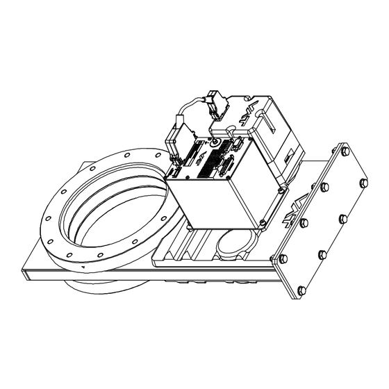
Page 114: Drawing
SPARE PARTS Series 642 12.1 Drawing Sample picture 114/119 Edition 2017-11-24 742280ED... -
Page 115: Valve Unit With Seals And Grease
(1 pc) (1 pc) (2 pcs) (2 pcs) (2 pcs) (4 pcs) (4 pcs) (4 pcs) Seal kit vacuum 97442-R1 225315 97446-R1 85047-R1 95939-R1 98472-R1 98474-R1 98476-R1 Feedtrough 91001-R1 227400 assembling tool VAT vacuum N-6951-012 grease (40g) 742280ED Edition 2017-11-24 115/119... -
Page 116: Controller
• DB-9 female POWER plug 242411 • DB-15 male SENSOR plug • DB-25 male INTERFACE plug Service Box 2 601BS-29NN-000 Control panel (rack-mount version of 602BS-29LE-000 Service Box 2) O-ring removal tool 234859 VAT valve cleaning tool 305709 116/119 Edition 2017-11-24 742280ED... - Page 117 Series 642 SPARE PARTS 12.1.3.1 Centering ring with Viton o-ring DN 63 / 2½” DN 80 / 3” DN 100 / 4” Valve size Product ordering number 64236 - ..64238 - ..64240 - ..Centering ring Aluminum 32036-QAZV...
-
Page 118: Appendix
APPENDIX Series 642 Appendix No information entered on time. 118/119 Edition 2017-11-24 742280ED... - Page 119 Series 642 This page left blank intentionally. 742280ED Edition 2017-11-24 119/119...
Need help?
Do you have a question about the 642 Series and is the answer not in the manual?
Questions and answers